
Loading ...
Loading ...
Loading ...
ADVANCED CONFIGURATION
113
Bus Key Configuration
The Bus key is used to configure the Serial bus inputs. The Bus
menu also features event tables to track and save your bus data.
The Bus key is used in conjunction with the Bus trigger (page 151)
to decode serial bus signals.
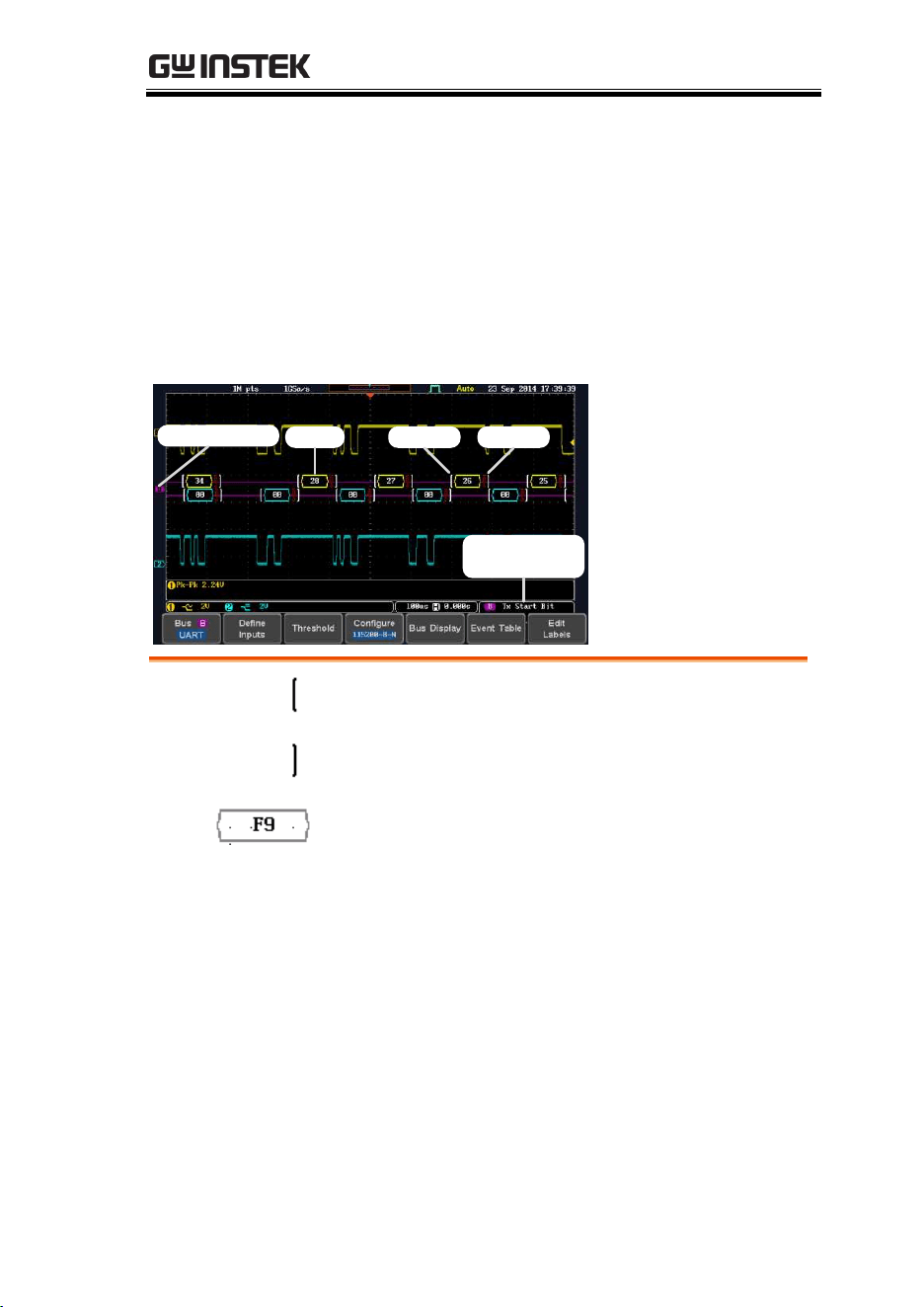
Bus Display
Bus indicator
Trigger
configuration
Data Start bit Stop bit
Start Bit/Start
of Frame
The Start bit is shown as an open bracket (Serial
bus data only).
Stop Bit/End
of Frame
The Stop bit is shown as a closed bracket (Serial
bus data only).
Data
Data packets/frames/words can be shown in Hex
or Binary. The color of the bus data indicates the
type of data or the channel the data is coming
from, depending on the bus type.
UART:
Color of packet = Color of source
channel.
I
2
C:
Color packet = SDA source channel.
CAN:
Purple = Error frame, Data length
control (DLC), Overload.
Yellow = Identifier.
Cyan = Data.
Orange = CRC.
Red = Bit stuffing error
Loading ...
Loading ...
Loading ...