1500KG HYDRAULIC COIL SPRING
COMPRESSING STATION
MODEL NO: RE231.V3
Thank you for purchasing a Sealey product. Manufactured to a high standard, this product will, if used according to these instructions,
and properly maintained, give you years of trouble free performance.
IMPORTANT: PLEASE READ THESE INSTRUCTIONS CAREFULLY. NOTE THE SAFE OPERATIONAL REQUIREMENTS, WARNINGS & CAUTIONS. USE
THE PRODUCT CORRECTLY AND WITH CARE FOR THE PURPOSE FOR WHICH IT IS INTENDED. FAILURE TO DO SO MAY CAUSE DAMAGE AND/OR
PERSONAL INJURY AND WILL INVALIDATE THE WARRANTY. KEEP THESE INSTRUCTIONS SAFE FOR FUTURE USE.
1. SAFETY
1.1. GENERAL SAFETY
IMPORTANT! Ensure Health & Safety, local authority regulations, and general safe workshop practices are adhered to when using this
equipment.
IMPORTANT! Wear approved safety hand and eye protection (standard spectacles are not adequate).
IMPORTANT! TRAPPING DANGER – Keep hands and fingers away from the spring and compressing jaws in use.
9 Familiarise yourself with the applications, limitations and potential hazards of the spring compressor.
▲ CAUTION! DO NOT use the spring compressor for a task it was not designed to perform.
▲ CAUTION! DO NOT allow untrained persons to use the spring compressor.
9 Keep the work area clean, uncluttered and ensure there is adequate lighting.
1.2. PRE-OPERATIONAL SAFETY
9 Apply a little transmission oil to the front and rear faces of the main upright to assist the smooth action of the compressor.
8 DO NOT operate compressor if damage is seen, parts are damaged or missing as this may cause failure and/or personal injury.
9 Before commencing compression, carry out a visual inspection of compressor to ensure pins are securely positioned and that there are
no sign of wear or fatigue – if found, DO NOT use and refer to your local Sealey stockist for advice and replacement parts.
9 Ensure jaw locating pins are properly positioned and safety clips are attached correctly.
9 Before commencing compression of spring, ensure coils of the spring are seated securely in the yokes of the compressor and cannot slide out
during compression.
9 If the restraint system is in use, ensure that the safety guard locks in place. Use the chain to secure the spring safely.
1.3. OPERATIONAL SAFETY
▲ CAUTION! Stop compressing the spring before the coils touch / bind.
▲ CAUTION! Before attempting to remove top strut-nut, always use a tool or similar to test if the compression has been relieved, DO NOT
use your hands / fingers.
9 When applying compression to the spring, always stand to one side of the compressor.
9 We recommend the use of purpose made strut tools to remove the top strut-nut.
9 Once compressed, and the strut removed, we recommend releasing the tension on the spring. DO NOT leave the spring under
compression in the machine unattended and DO NOT leave in compression for prolonged periods, i.e. overnight.
9 Before releasing the compression ensure that the top strut-nut is securely tightened to the manufacturer’s tolerance.
9 Release the compression slowly keeping your hands and fingers away from the spring assembly.
9 Be sure that the tension on the spring is fully controlled by the strut assembly before removing it from the yokes of the compressor.
1.4. POST OPERATIONAL SAFETY
9 When not in use, clean and store the spring compressor in a safe, dry, childproof location.
9 Maintain the spring compressor in good condition. Replace with genuine Sealey parts only.
9 Unauthorised parts may be dangerous and will invalidate the warranty.
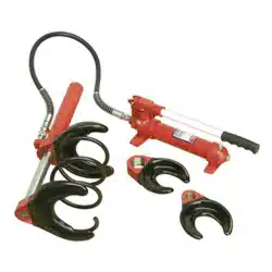
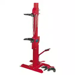
2. INTRODUCTION
1500kg foot operated hydraulic unit. Quicker and easier than using ratchet driven spring
compressor. Plastic coated yokes reduce the risk of spring slippage or damage and are
suitable for springs from Ø80mm to Ø175mm.
3. SPECIFICATION
Model no ...............................................................RE231.V3
Max. load ................................................................... 1500kg
Upper yoke positions ........................................................... 7
Lower yoke travel ....................................................... 340mm
Spring diameter ..................................................... 80-175mm
Actuation ................................................................ foot pedal
Coil spring compressor restraint system (not supplied)
................................................................................. RE23RS
Refer to
instruction
manual
RE231.V3 | Issue:4 (3) 18/05/20
Original Language Version
© Jack Sealey Limited
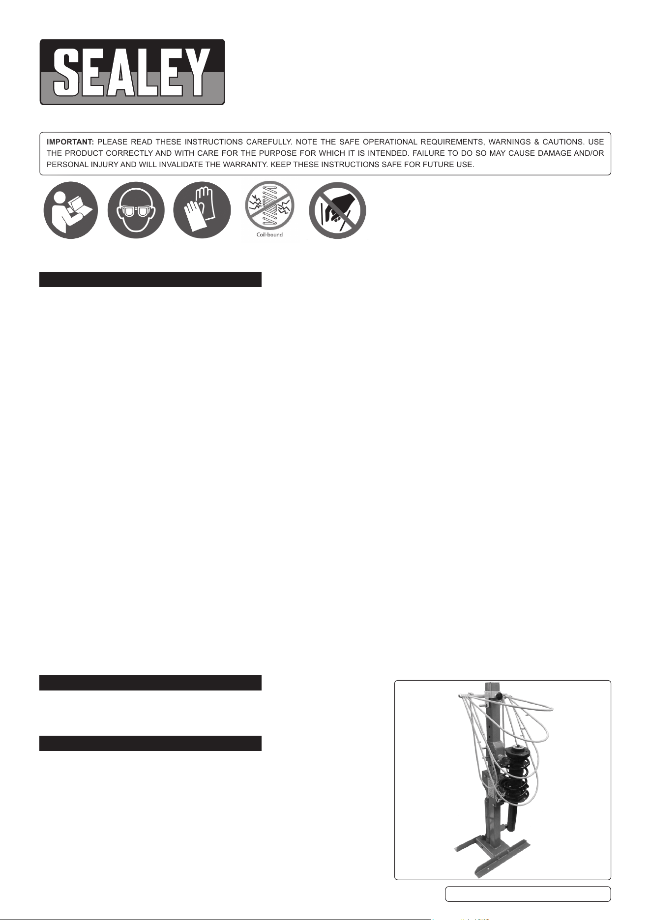
With optional
RE23RS
fitted
Wear eye
protection
Wear protective
gloves
Beware
coil binding
No reaching in
4. ASSEMBLY
Refer to attached parts diagram.
4.1. Attachthebracketstothebaseusingthexingsshownonthepartsdiagram.
4.2. Attach the pedal to the pump and secure.
4.3. Attachthechains,onetoeachsideoftheupperstrutsupport,refertog.1.
IMPORTANT:securethemachinetotheoor.Thebracketsaredrilledtoaccept
boltswhichshouldbesecuredtosuitablexings.
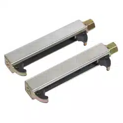
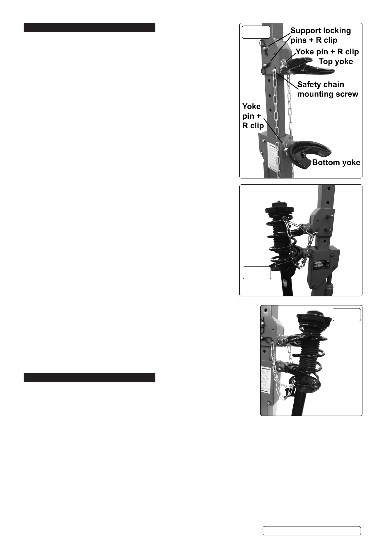
4.4. MOUNTING THE YOKES (See g.1)
4.4.1. Push the required top yoke onto the yoke mounting spigot.
4.4.2. Secure with the yoke retaining pin and insert the ‘R’ clip.
4.4.3. Repeat to secure the lower yoke with it’s pin and ‘R’ clip.
4.4.4. Make sure that the yokes are installed with the bottom yoke facing up and the
top yoke facing down.
4.5. COMPRESSING A SPRING
4.5.1. Move the upper support to the required height in order to accommodate the
spring.Dothisbyreleasingthetwouppersupportlockingpins(g.1),moving
the support and replacing the pins, ensuring that the ‘R’ clips are inserted.
4.5.2. Place the spring between the yokes and wrap the safety chains around the
spring.Positiononechainaroundacoilprotrudingabovethetopyoke,(g.2A)
andtheotherchainbelowthebottomyoke(g.2B).Checkthatneither
chain could be trapped between the coils. Ensure that the chains are as tight as
possible.
4.5.3. Apply light hydraulic pressure with the pump pedal and check that the spring is
seated correctly.
8 DO NOT compress the spring until the coils touch, only compress until
the top nut is free.
4.5.4. If the spring is seated correctly, continue to compress the spring, standing to the
side of the machine.
4.5.5. Compress the spring gradually, making sure that the spring stays seated in the
yokes.
4.5.6. When compressing conical springs; the centre line of the spring should remain
parallel to the compressor body.
WARNING: Check that the nut is free by using a metal or wooden item.
8 DO NOT checkwithngersorhands.
4.5.7. It is recommended that a purpose-made strut nut socket is used to remove
the nut. Support the shock absorber to prevent it falling clear when
released.
8 DO NOT leave the spring compressed unattended;
release the pressure on the spring if it is to be left for any time.
4.5.8. Decompress the spring by pressing the release valve pedal (next to the
pump pedal) gradually.
4.5.9. Torebuildthestrutassembly,compressthespringandinsert
the shock absorber through the lower yoke and reattach the
top plate and nut.
4.5.10. Release the compression slowly, keeping hands well away from the spring.
4.5.11. Ensure that the spring tension is constrained by the strut assembly before
releasing it from the yokes of the spring compressor.
4.5.12. When re-fitting the strut to the vehicle, the locking plate nut will need to be fully tightened
using a torque wrench, to a setting in accordance with the vehicle manufacturer’s
specification.
5. MAINTENANCE
5.1. Before each use, check the compressor to ensure it is not damaged or worn.
If in any doubt DO NOT use the unit. Remove it from service immediately and
contact your local Sealey stockist for advice/repairs.
5.1.1. Refilling the hydraulic system with oil is rarely necessary but the level should
becheckedintheeventofalossofperformance.Tocheckoillevel,ensurethe
ram is fully lowered, remove filler plug (refer to parts diagram) and check that
level is within 10mm of filler hole. Add Sealey hydraulic jack oil if necessary.
NOTE:
Use a good quality jack oil, such as SEALEY HYDRAULIC JACK OIL.
g.2A
g.2B
g.1
Chain around spring
above top yoke
Chain
around
spring
below
bottom
fyoke
Original Language Version
© Jack Sealey Limited
RE231.V3 | Issue:4 (3) 18/05/20

Original Language Version
© Jack Sealey Limited
Sealey Group, Kempson Way, Suffolk Business Park, Bury St Edmunds, Suffolk. IP32 7AR
01284 757500 01284 703534 sales@sealey.co.uk www.sealey.co.uk
ENVIRONMENT PROTECTION
Recycle unwanted materials instead of disposing of them as waste. All tools, accessories and packaging should be sorted, taken to
a recycling centre and disposed of in a manner which is compatible with the environment. When the product becomes completely
unserviceable and requires disposal, drain any fluids (if applicable) into approved containers and dispose of the product and fluids
according to local regulations.
Note: It is our policy to continually improve products and as such we reserve the right to alter data, specifications and component parts without prior
notice.
Important: No Liability is accepted for incorrect use of this product.
Warranty: Guarantee is 12 months from purchase date, proof of which is required for any claim.
RE231.V3 | Issue:4 (3) 18/05/20