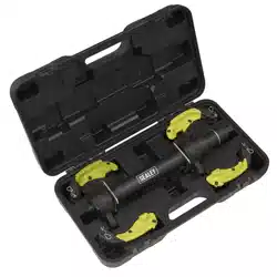
COIL SPRING COMPRESSOR
RESTRAINT SYSTEM
MODEL NO: RE23RS
Thank you for purchasing a Sealey product. Manufactured to a high standard, this product will, if used according to these
instructions, and properly maintained, give you years of trouble free performance.
IMPORTANT: PLEASE READ THESE INSTRUCTIONS CAREFULLY. NOTE THE SAFE OPERATIONAL REQUIREMENTS, WARNINGS & CAUTIONS. USE
THE PRODUCT CORRECTLY AND WITH CARE FOR THE PURPOSE FOR WHICH IT IS INTENDED. FAILURE TO DO SO MAY CAUSE DAMAGE AND/OR
PERSONAL INJURY AND WILL INVALIDATE THE WARRANTY. KEEP THESE INSTRUCTIONS SAFE FOR FUTURE USE.
1. SAFETY
1.1. GENERAL SAFETY.
WARNING! Ensure Health & Safety, local authority, and general workshop practice regulations are adhered to when using this equipment.
WARNING! Wear approved safety hands, face and eye protection (full face visor is essential).
WARNING! TRAPPING DANGER – Keep hands and fingers away from the spring and compressing jaws in use.
9 Keep the work area clean, uncluttered and ensure there is adequate lighting.
9 Maintain correct balance and footing. Ensure the floor is not slippery and wear non-slip shoes.
9 Remove ill-fitting clothes. Remove ties, watches, rings, other loose jewellery. Contain and/or tie back long hair.
9 Wear appropriate protective clothing (leather gauntlets and leather apron for example).
9 Familiarise yourself with the applications, limitations and potential hazards of the compression spring restraint.
8 DO NOT allow untrained persons to use the compression spring restraint.
1.2. PRE OPERATIONAL SAFETY.
9 Strut and Spring Compression station should be securely bolted to the workshop floor before use.
8 DO NOT operate spring compressor if parts are damaged or missing as this may cause failure and/or personal injury.
9 Before commencing compression of spring, ensure coils of the spring are seated securely in the jaws of the compressor and
cannot slide out during compression.
9 Always fit the restraining chain around the spring (ensure the restraining chain is not trapped in the coils of the spring as compressed).
9 Always fit the coil spring compressor restraint system.
1.3. OPERATIONAL SAFETY.
9 When applying compression to the spring, always stand to one side of the unit.
▲ DANGER! Stop compressing the spring as soon as the top cap of shock absorber is no longer under load. Never allow coils to touch
each other.
9 Before attempting to remove top cap nut, always use a tool to test if the compression has been relieved.
8 DO NOT use your hands/fingers to test for strut to spring forces.
9 We recommend the use of purpose made strut tools to remove the top-nut from the shock piston.
9 Once compressed, and the strut removed, we recommend releasing the tension on the spring.
8 DO NOT leave the spring under compression in the machine unattended.
8 DO NOT leave in compression for prolonged periods, i.e. overnight.
9 Before releasing the compression ensure that the top strut-nut is securely fastened to the maker’s tolerance.
9 Release the compression slowly keeping your hands and fingers away from the spring assembly.
9 Be sure that the tension on the spring is fully controlled by the strut assembly before removing it from the jaws of the compressor.
1.4. POST OPERATIONAL SAFETY.
9 When not in use, clean and store the spring compressor including restraint in a safe, dry, childproof location.
9 Maintain the spring compressor and restraint in good condition. Replace or repair damaged parts. Use genuine parts only. Unauthorised
parts may be dangerous and will invalidate the warranty.
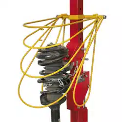
2. INTRODUCTION
Safety restraint system designed for use with Model No’s RE231, RE2311 and RE232 Coil Spring Compressors. Quickly installed and fast and
simple to operate in use.
RE231/RE2311/RE232 Not included.
3. SPECIFICATION
Envelope: . . . . . . . . . . . . . . . . . . . . . 645mm x 365mm
Restraint rod diameter:......................8mm
Pillar adaptor size: .................60mm x 60mm
Pinch knob:................................ M8
RE23RS | Issue 3 (U) 09/03/20
Original Language Version
© Jack Sealey Limited
Refer to
instructions
Wear protective
gloves
Wear safety
footwear
Wear protective
clothing
Wear a face
shield
Beware
coil binding
No reaching in
RE23RS | Issue 3 (U) 09/03/20
Original Language Version
© Jack Sealey Limited
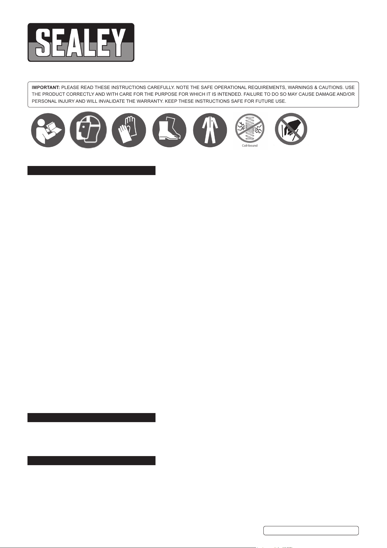
CONTENTS
Item no Description Qty
1 Pillar adaptor bar 1
2 Pivot spindle 1
3 Plain washer M12 dia 2
4 Hexagon stiff nut M12 2
5 Side restraint hoop right hand 1
6 Side restraint hoop left hand 1
7 Inner restraint hoop 1
8 Intermediate restraint hoop 1
9 Intermediate restraint hoop 1
10 Outer restraint hoop 1
11 Pinch knob M8 X 16 1
12 Pin 1
13 R clip 1
4. ASSEMBLY
4.1. Empty contents of packaging and display on a bench top to identify and check for missing or damaged parts.
In the unlikely event of missing or damaged parts, consult your Sealey Stockist immediately.
4.2. SEQUENCE OF ASSEMBLY
WARNING! Ensure there is not a spring under load on the Compressing Station before assembling.
4.3. NOTE: All instructions are while looking at the front of the Compressing Station (the side with yokes on).
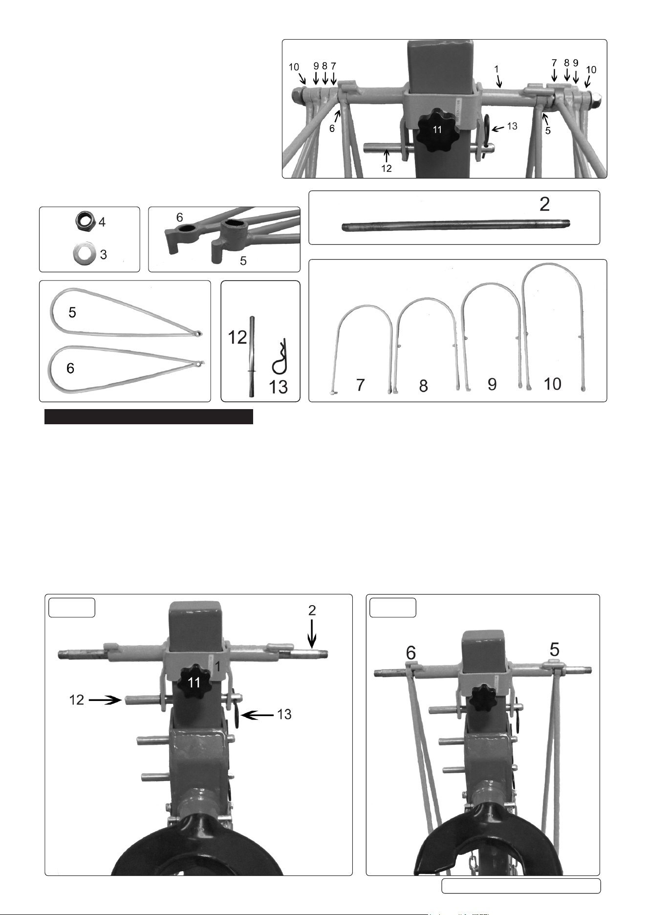
4.4. Slide the pillar adaptor bar (Item 1) over the main pillar of the coil spring compressing station (Models RE231, RE2311 or RE232 -
notincluded)withthepinchknobfacingthesamedirectionastheyokes.(front)(g.1).Secureinplacebyslidingthepin(Item12)
throughtheappropriateholefromlefttorightonthemainbeamandinsertthe‘R’clip(Item13)throughthepintosecure(g.1).
NOTE: Height is determined by the size of the spring. Adjust when ready to use. Tighten the pinch knob.
4.5. Insertthepivotspindle(Item2)throughthepillaradaptorbar(Item1)withbothendsprotrudingevenly(g.1).
4.6. Place the right hand restraint hoop (Item 5) (with the larger boss) onto the right hand side of the spindle with the lug facing the centre
andsetthelugbehindthexedlugonthepillaradaptorbar(g.2).Placethelefthandrestrainthoop(Item6)onthelefthandside
withthelugfacinginwardsandsetbehindthexedlugonthepillaradaptorbar,asshownin(g.2).
4.7. NOTE: (Item 5) has a larger boss than (Item 6) therefore the positioning is important!
g.1 g.2
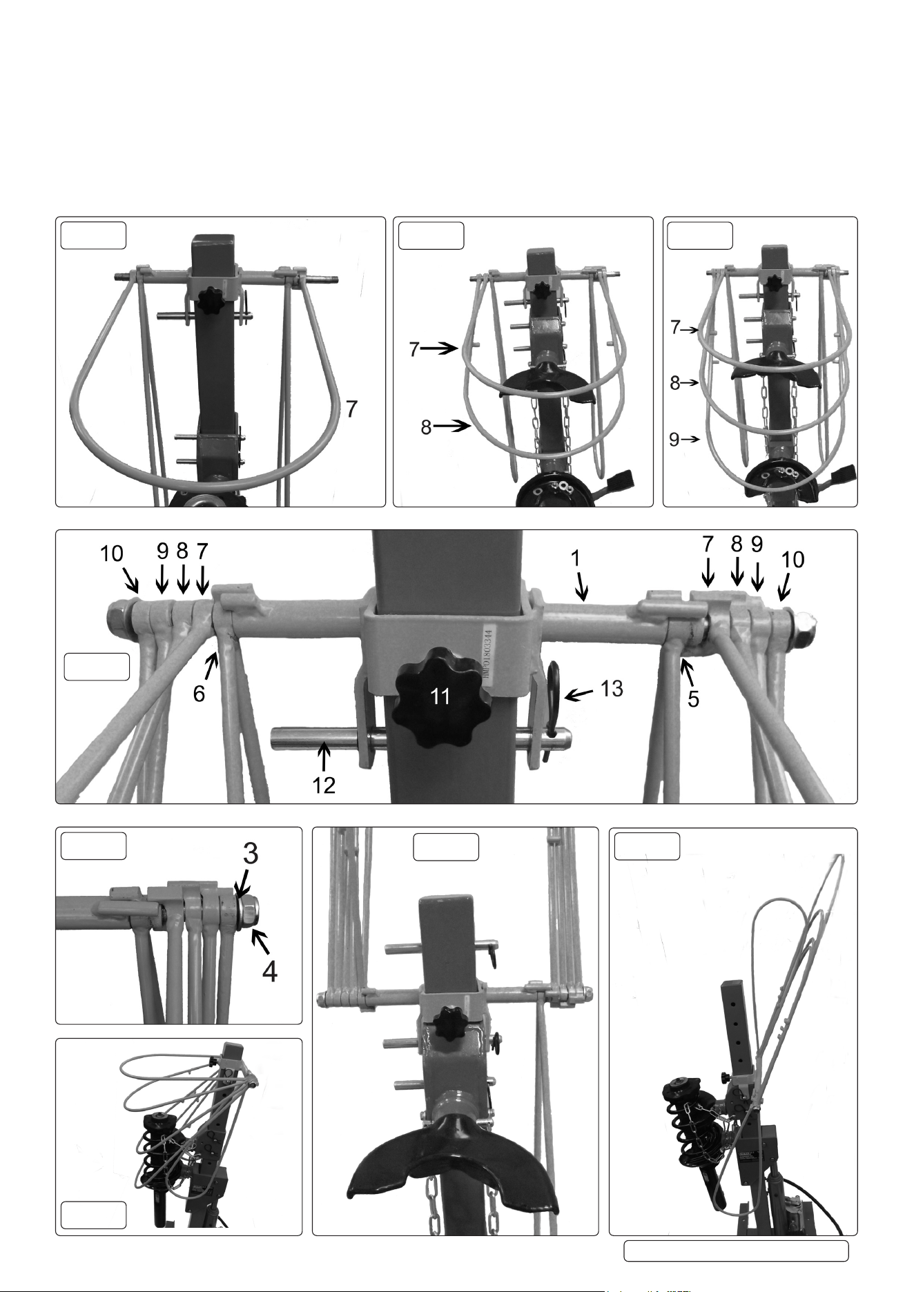
4.8. Place(Item7)withthelugsontherighthandside,overbothendsofthepivotspindlewiththelugssetbehindxedlug.(g.3).
4.9. NOTE: (Items 8-10) have side lugs, which are all positioned on the underside, they lift each hoop in turn when cage is lifted up.
4.10. Place (item 8) with the lug on the right hand side, below (Item 7) and slide each end over the pivot spindle with lug set behind the lug
on(Item7).Repeatwith(Items9&10)(g.4,5&6).
4.11. Place washer (item 3) at each end of spindle and wind on hexagon stiff nuts (item 4) with equal engagement, without clamping the
assembly. All loops to pivot freely under their own weight, limited only by the lugs, the right hand side hoop has limited movement.
4.12. Thelefthandsidehooprotatesfullytoallowaccesstothepinsinthemainpillar.(g.9&10).
WARNING! Always fit the restraining chains around the spring (fig.10)
WARNING! Spring compression station should be securely bolted to the workshop floor before use.
RE23RS | Issue 3 (U) 09/03/20
Original Language Version
© Jack Sealey Limited
g.8
g.3
g.4 g.5
g.6
g.7
g.9
g.10

RE23RS | Issue 3 (U) 09/03/20
Original Language Version
© Jack Sealey Limited
Sealey Group, Kempson Way, Suffolk Business Park, Bury St Edmunds, Suffolk. IP32 7AR
01284 757500 01284 703534 sales@sealey.co.uk www.sealey.co.uk
ENVIRONMENT PROTECTION
Recycle unwanted materials instead of disposing of them as waste. All tools, accessories and packaging should be sorted, taken to
a recycling centre and disposed of in a manner which is compatible with the environment. When the product becomes completely
unserviceable and requires disposal, drain any fluids (if applicable) into approved containers and dispose of the product and fluids
according to local regulations.
Note: It is our policy to continually improve products and as such we reserve the right to alter data, specifications and component parts without prior notice.
Important: No Liability is accepted for incorrect use of this product.
Warranty: Guarantee is 12 months from purchase date, proof of which is required for any claim.
5. OPERATION
5.1. All the loops of the restraint system, except side restraint (Item 5) can be readily swept up and away from the work area (fig.9 & 10).
These loops go beyond the vertical to a self supported leaning position. Item 5 sweep path is limited by a mechanical stop.
5.2. Side restraint (Item 6) lifts and holds the other hoops in place, this allows access to the pins on the main beam (fig.9 & 10).
5.3. Ensure cage is fully lowered before compressing a spring.
6. MAINTENANCE
6.1. The robust nature of the restraint system means that it only requires cleaning after use with a lightly oiled cloth.
6.2. Check freedom of loop sweep, which should result from the cleaning/lubricating process in 6.1.
6.3. Replace immediately any part that is or appears to be damaged.