Loading ...
Loading ...
Loading ...
7
8
8.2
B
A
C
E
D
G
J
L
K
M
J
F
H
F
I
N
R
Q
S
O
P
12
6
5
2
4
C
B
A
D
3
1
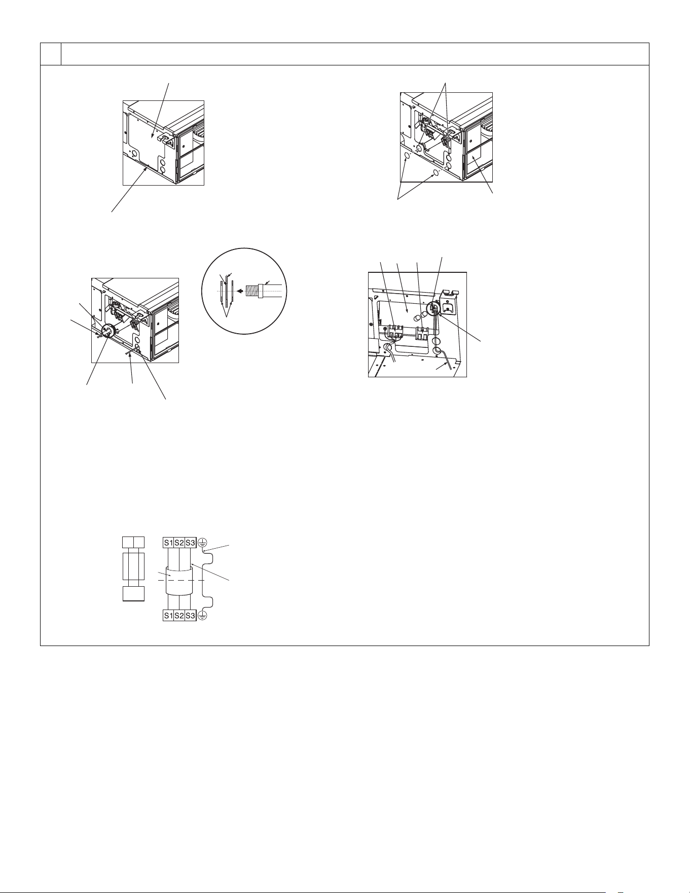
[Fig. 8-2-1]
[Fig. 8-2-3]
[Fig. 8-2-5]
[Fig. 8-2-2]
[Fig. 8-2-4]
A Screw holding cover (1pc)
B Cover
C Terminal box
D Knockout hole
E Remove
F Use PG bushing to keep the weight of the cable and external force from being
applied to the power supply terminal connector. Use a cable tie to secure the cable.
G Power source wiring
H Use ordinary bushing
I Transmission wiring
J Conduit
K Side frame
L Knockout hole (for power source wiring)
M Washer (accessory)
N Terminal block for power source and indoor transmission
O Terminal block for wired remote controller
P Indoor controller board
Q Radio frequency interface is installed on Indoor controller board
R CN105 (RED/5P)
S Wiring for radio frequency interface
A Indoor terminal block
B Earth wire (green/yellow)
C Indoor/outdoor unit connecting wire 3-core
1.5 mm
2
[AWG 16] or more
D Outdoor terminal block
1 Connecting cable
Cable 3-core 1.5 mm
2
[AWG 16], in
conformity with Design 245 IEC 57.
2 Indoor terminal block
3 Outdoor terminal block
4 Always install an earth wire (1-core 1.5 mm
2
[AWG 16]) longer than other cables
5 Wired remote controller cable
Wire No × size (mm
2
) : Cable 2C × 0.3
This wire accessory of remote controller
(wire length : 10 m [32 ft], non-polar. Max.
500 m [1640 ft])
6 Wired remote controller
KJ79P806H01.book 7 ページ 2021年12月13日 月曜日 午後2時15分
Loading ...
Loading ...
Loading ...