Loading ...
Loading ...
Loading ...
20
9. Test run
9.3. Self-check
Refer to the installation manual that comes with each remote controller for details.
RF thermostat is not established.
• Refer to the following tables for details on the check codes. (Wireless remote controller)
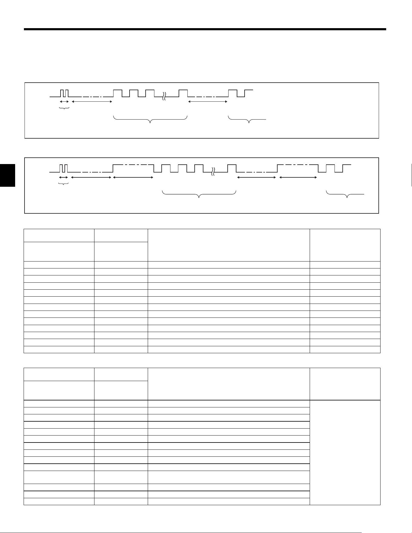
[Output pattern A]
[Output pattern B]
[Output pattern A] Errors detected by indoor unit
[Output pattern B] Errors detected by unit other than indoor unit (outdoor unit, etc.)
IR wireless remote controller
Wired remote controller
RF thermostat
Symptom Remark
Beeper sounds/OPERATION
INDICATOR lamp flashes
(Number of times)
Check code
1 P1 Intake sensor error
2 P2, P9 Pipe (Liquid or 2-phase pipe) sensor error
3 E6, E7 Indoor/outdoor unit communication error
4 P4 Drain sensor error
5 P5 Drain pump error
6 P6 Freezing/Overheating safeguard operation
7 EE Communication error between indoor and outdoor units
8 P8 Pipe temperature error
9 E4 Remote controller signal receiving error
10 – –
11 – –
12 Fb Indoor unit control system error (memory error, etc.)
No sound – – No corresponding
IR wireless remote controller
Wired remote controller
RF thermostat
Symptom Remark
Beeper sounds/OPERATION
INDICATOR lamp flashes
(Number of times)
Check code
1 E9 Indoor/outdoor unit communication error (Transmitting error) (Outdoor unit)
For details, check the LED
display of the outdoor controller
board.
2 UP Compressor overcurrent interruption
3 U3, U4 Open/short of outdoor unit thermistors
4 UF Compressor overcurrent interruption (When compressor locked)
5 U2 Abnormal high discharging temperature/49C worked/insufficient refrigerant
6 U1, Ud Abnormal high pressure (63H worked)/Overheating safeguard operation
7 U5 Abnormal temperature of heat sink
8 U8 Outdoor unit fan protection stop
9 U6 Compressor overcurrent interruption/Abnormal of power module
10 U7 Abnormality of super heat due to low discharge temperature
11 U9, UH
Abnormality such as overvoltage or voltage shortage and abnormal
synchronous signal to main circuit/Current sensor error
12 – –
13 – –
14 Others Other errors (Refer to the technical manual for the outdoor unit.)
Beeper sounds
Number of blinks/beeps in pattern indicates the check
code in the following table (i.e., n=5 for “P5”)
OPERATION
INDICATOR
lamp blinking
pattern
Self-check
starts
(Start signal
received)
Beep
Beep
Beep
Beep Beep
Beep Beep
· · · Repeated
On
0.5 sec.
On
0.5 sec.
On
0.5 sec.
Off
Approx. 2.5 sec.
On
0.5 sec.
Off
Approx. 2.5 sec.
On
0.5 sec.
On
0.5 sec.
Number of blinks/beeps in pattern indicates
the check code in the following table
1
st
2
nd
3
rd
n
th
1
st
2
nd
Beeper sounds
Number of blinks/beeps in pattern indicates the check
code in the following table (i.e., n=5 for “U2”)
OPERATION
INDICATOR
lamp blinking
pattern
Self-check
starts
(Start signal
received)
Beep
Beep
Beep
· · · Repeated
On
0.5 sec.
On
0.5 sec.
Off
Approx. 2.5 sec.
On
0.5 sec.
On
0.5 sec.
On
0.5 sec.
Number of blinks/beeps in pattern indicates
the check code in the following table
1
st
2
nd
3
rd
n
th
1
st
2
nd
On
Approx. 3 sec.
Off
Approx. 2.5 sec.
On
0.5 sec.
Beep
Beep
Beep
Beep
On
Approx. 3 sec.
KJ79P806H01.book 20 ページ 2021年12月13日 月曜日 午後2時15分
Loading ...
Loading ...
Loading ...