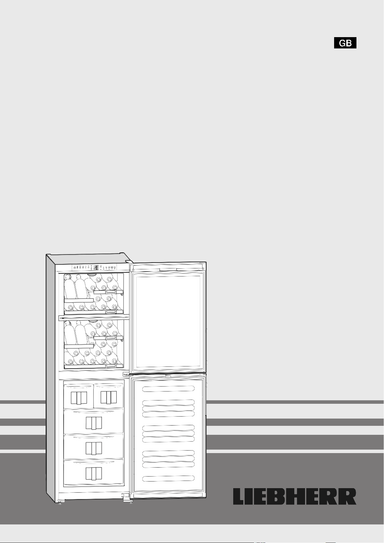
Operating and installation instructions
Upright refrigerator with BioFresh compartment
30/08
7082648 - 01
SKBes/SKB/KB/KBes 31/36/42 ... 6
Contents
1 Appliance at a glance............................................ 2
1.1 Range of appliance use............................................ 2
1.2 Conformity................................................................ 2
1.3 Description of appliance and equipment.................. 2
1.4 External dimensions of the appliance....................... 3
1.5 Net@Home............................................................... 3
2 General safety information................................... 3
3 Controls and displays........................................... 4
3.1 Operating and control elements............................... 4
3.2 Temperature display................................................. 4
4 Putting into operation............................................ 4
4.1 Changing over the door hinges................................ 4
4.2 Insertion into a row of kitchen units........................... 7
4.3 Transporting the appliance....................................... 7
4.4 Installing the appliance............................................. 7
4.5 Disposing of packaging............................................ 8
4.6 Connecting the appliance......................................... 8
4.7 Switching on the appliance....................................... 8
5 Control.................................................................... 8
5.1 Saving energy.......................................................... 8
5.2 Brightness of the temperature display...................... 8
5.3 Child proofing........................................................... 8
5.4 Door alarm................................................................ 8
5.5 Refrigerator compartment........................................ 8
5.6 BioFresh compartment............................................. 10
6 Maintenance........................................................... 11
6.1 Cleaning the appliance............................................. 11
6.2 Changing the interior light with bulb.......................... 12
6.3 Customer service..................................................... 12
7 Malfunction............................................................. 12
8 Decommissioning.................................................. 13
8.1 Switching off the appliance....................................... 13
8.2 Taking the appliance out of service.......................... 13
9 Disposing of the appliance................................... 13
The manufacturer works constantly on the further development
of all the types and models. Therefore please understand that we
have to reserve the right to make design, equipment and techni-
cal modifications.
To get to know all the benefits of your new appliance, please read
the information contained in these instructions carefully.
The instructions apply to several models. Differences may occur.
Text relating only to specific appliances is marked with an aster-
isk (*).
Instructions for action are marked with a
, the results of
action are marked with a .
1 Appliance at a glance
1.1 Range of appliance use
The appliance is suited only for cooling food. In the case of com-
mercial food cooling, the pertinent statutory regulations have to
be observed. The appliance is not suited for storing and cooling
pharmaceuticals, blood plasma, laboratory preparations or sim-
ilar substances and products subject to the Medical Devices Di-
rective 2007/47/EC. Any misuse of the appliance may result in
damage to or spoilage of the stored goods. Furthermore, the ap-
pliance is unsuited for use in areas exposed to an explosion haz-
ard.
The appliance is set to operate within specific ambient temper-
ature limits according to its climate rating. The correct climate
rating for your appliance is indicated on the type plate.
Note
u
Compliance with the ambient temperatures indicated is re-
quired, otherwise the cooling performance is reduced.
Climate rat-
ing
for ambient temperatures of
SN 10 °C to 32 °C
N 16 °C to 32 °C
ST 16 °C to 38 °C
T 16 °C to 43 °C
1.2 Conformity
The refrigerant circuit has been tested for leaks. The appliance
complies with current safety regulations and EC directives
2006/95/EC and 2004/108/EC.
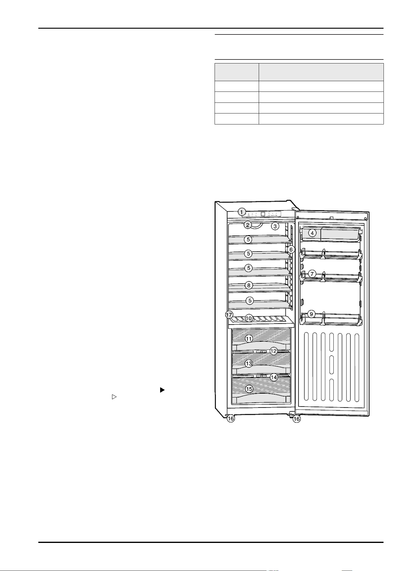
1.3 Description of appliance and equip-
ment
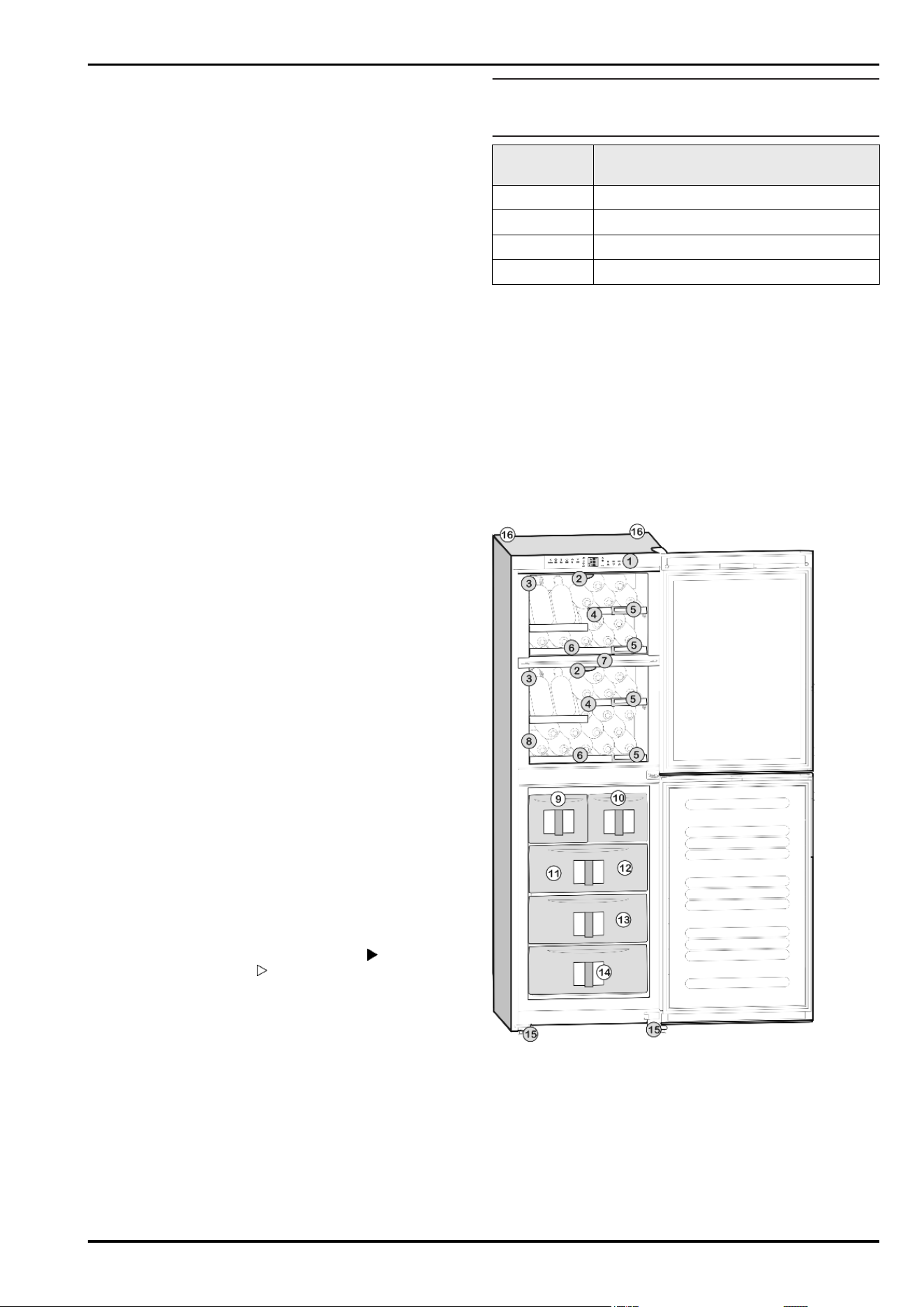
Fig. 1
(1) Operating panel (10) Bottle shelf
(2) Fan (11) BioFresh compartment,
Drysafe
(3) Interior light, bulb* (12) HydroSafe control
(4) Box shelves, removable (13) BioFresh compartment,
Hydrosafe
(5) Glass shelves, relocata-
ble
(14) HydroSafe control
(6) Interior light, LED* (15) BioFresh compartment,
Hydrosafe
(7) Rack for tinned food, re-
locatable
(16) Height-adjustable foot
(8) Glass shelf, sectioned,
relocatable
(17) Type plate
(9) Bottle rack
Appliance at a glance
2
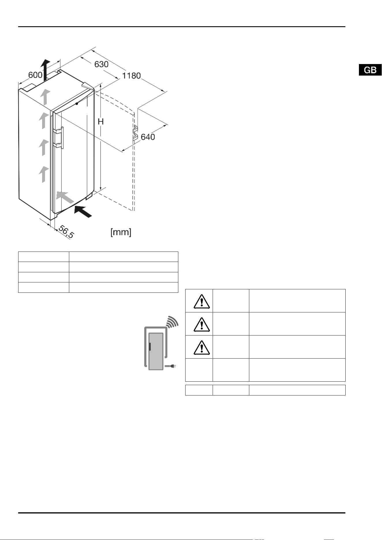
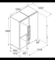
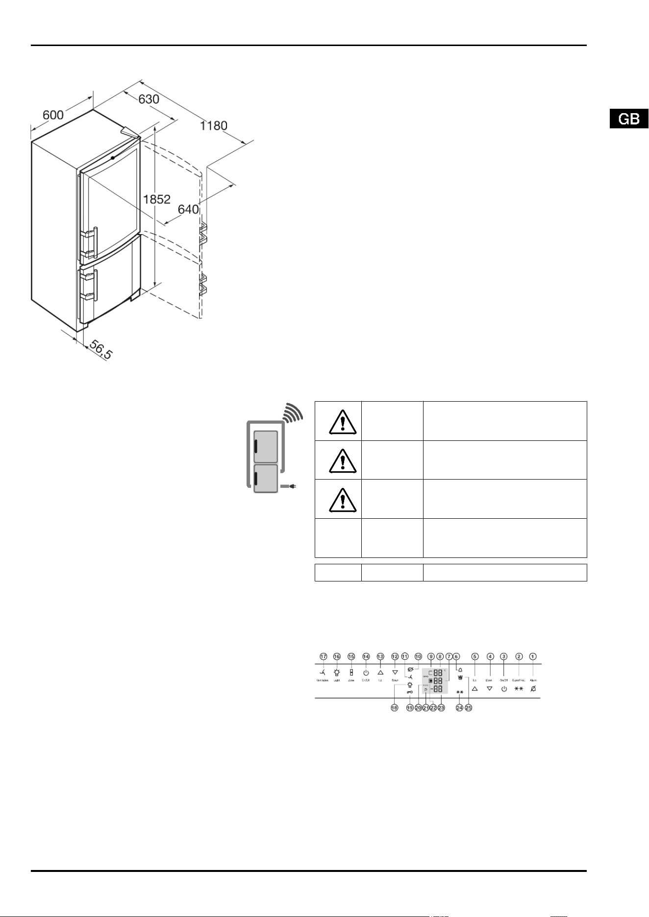
1.4 External dimensions of the appliance
Fig. 2
Designation H (mm)
KB 31 1458
KB 36 1655
KB 42 1852
1.5 Net@Home
The appliance can be provided with the retrofit
modules for the HomeDialog system or the serial
interface (RS 232), depending on model and
equipment. The modules are available from your
specialist dealer.
You will find more information on the internet at
www.liebherr.com.
2 General safety information
Danger for the user:
-
This appliance is not designed for persons (including children)
with physical, sensory or mental impairment or persons not
having sufficient experience and knowledge, unless they are
instructed in the use of the appliance and are initially super-
vised by a person responsible for their safety. Keep children
under supervision to ensure they do not play with the appli-
ance.
-
In case of a fault, pull out the mains plug (not by pulling the
connecting cable) or switch off the fuse.
-
Have any repairs to or intervention in the appliance, and any
change of the mains power cable, carried out by the customer
service only or by other specialised personnel trained for the
purpose.
-
When disconnecting the appliance from the supply, always
take hold of the plug. Do not pull the cable.
-
Install and connect the appliance only as instructed.
-
Please keep these instructions in a safe place and pass them
on to any subsequent owners.
Fire hazard:
-
The refrigerant R 600a is environmentally friendly but flam-
mable. Escaping refrigerant may ignite.
•
Do not damage the refrigerant circuit pipes.
•
Do not allow naked flames or ignition sources to enter the
appliance.
•
Do not use any electrical appliances in the interior (e.g.
steam cleaners, heaters, ice cream maker etc.).
•
If refrigerant escapes: eliminate naked flames or sources
of ignition from the vicinity. Pull out the power plug. Venti-
late the area well. Notify customer service.
-
Do not store explosives or sprays using combustible propel-
lants such as butane, propane, pentane, etc. in the appliance.
Respective spray cans can be identified by reference to the
contents printed on the can or by a flame symbol. Gases pos-
sibly escaping may ignite due to electrical components.
-
Do not place any burning candles, lamps or other items with
naked flames on or in the appliance.
-
Only store high-percentage alcohol in tightly sealed, upright
containers. Alcohol possibly escaping may ignite due to elec-
trical components.
Danger of tipping and falling:
-
Do not misuse the plinth, drawers, doors etc. as a step or for
support. This applies particularly to children.
Danger of food poisoning:
-
Do not consume food which has been stored too long.
Danger of frostbite, numbness and pain:
-
Avoid lasting skin contact with cold surfaces or refrigerated/
frozen food or take protective steps, e.g. wear gloves. Do not
consume ice cream, water ice or ice cubes immediately and
do not consume them too cold.
Please observe the specific information in the other sec-
tions:
DANGER identifies a situation involving direct
danger which, if not obviated, may re-
sult in death or severe bodily injury.
WARNING identifies a dangerous situation
which, if not obviated, may result in
death or severe bodily injury.
CAUTION identifies a dangerous situation
which, if not obviated, may result in
minor or medium bodily injury.
NOTICE identifies a dangerous situation
which, if not obviated, may result in
damage to property.
Note identifies useful information and tips.
General safety information
3
3 Controls and displays
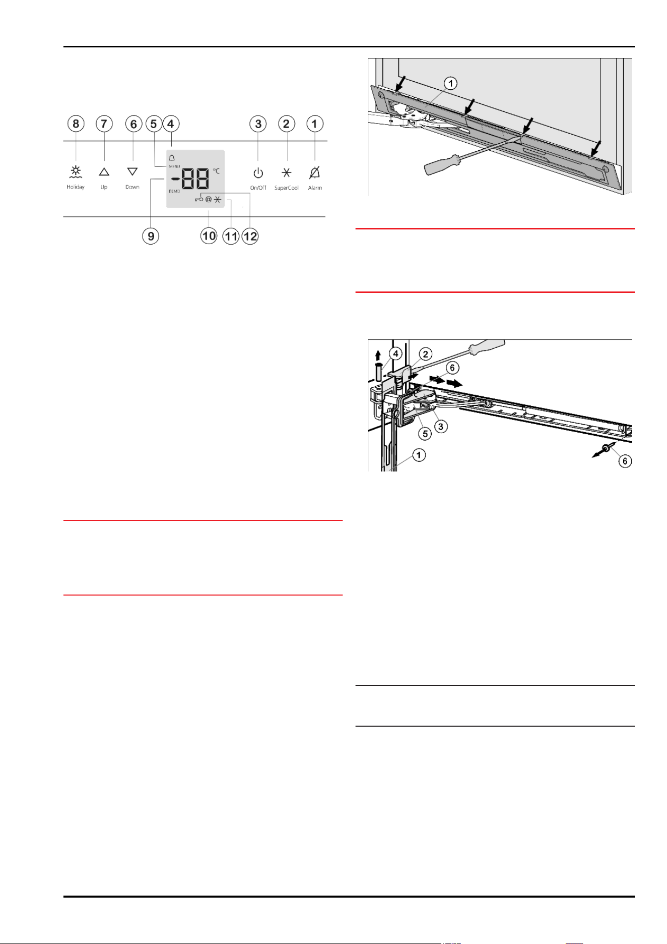
3.1 Operating and control elements
Fig. 3
(1) Alarm button (7) Up setting button
(2) SuperCool button (8) Holiday button
(3) On/Off button (9) Temperature display
(4) Alarm symbol (10) Net@Home symbol
(5) Menu symbol (11) SuperCool symbol
(6) Down setting button (12) Child-proofing symbol
3.2 Temperature display
The following are displayed in normal operation:
-
the average cooling temperature
The following displays indicate malfunction. You will find possible
causes and corrective action in the section on troubleshooting.
-
F0 to F9
4 Putting into operation
4.1 Changing over the door hinges
You can change over the door hinges if necessary.
NOTICE*
Risk of damage to side-by-side appliances due to condensation!
When a Side-by-Side appliance (S…) is fitted together with a
second appliance (as a SBS combination), the door hinges must
remain as delivered.
u
Do not change over the door hinges.
Ensure that the following tools are to hand:
q
Torx 25
q
Torx 15
q
Screwdriver
q
Cordless screwdriver, if necessary
q
Second person for fitting work, if needed
4.1.1 Detaching the soft stop unit. *
For appliances with soft stop mechanism start with this point.
For appliances without soft stop mechanism start with the
point 'Detaching the door'.
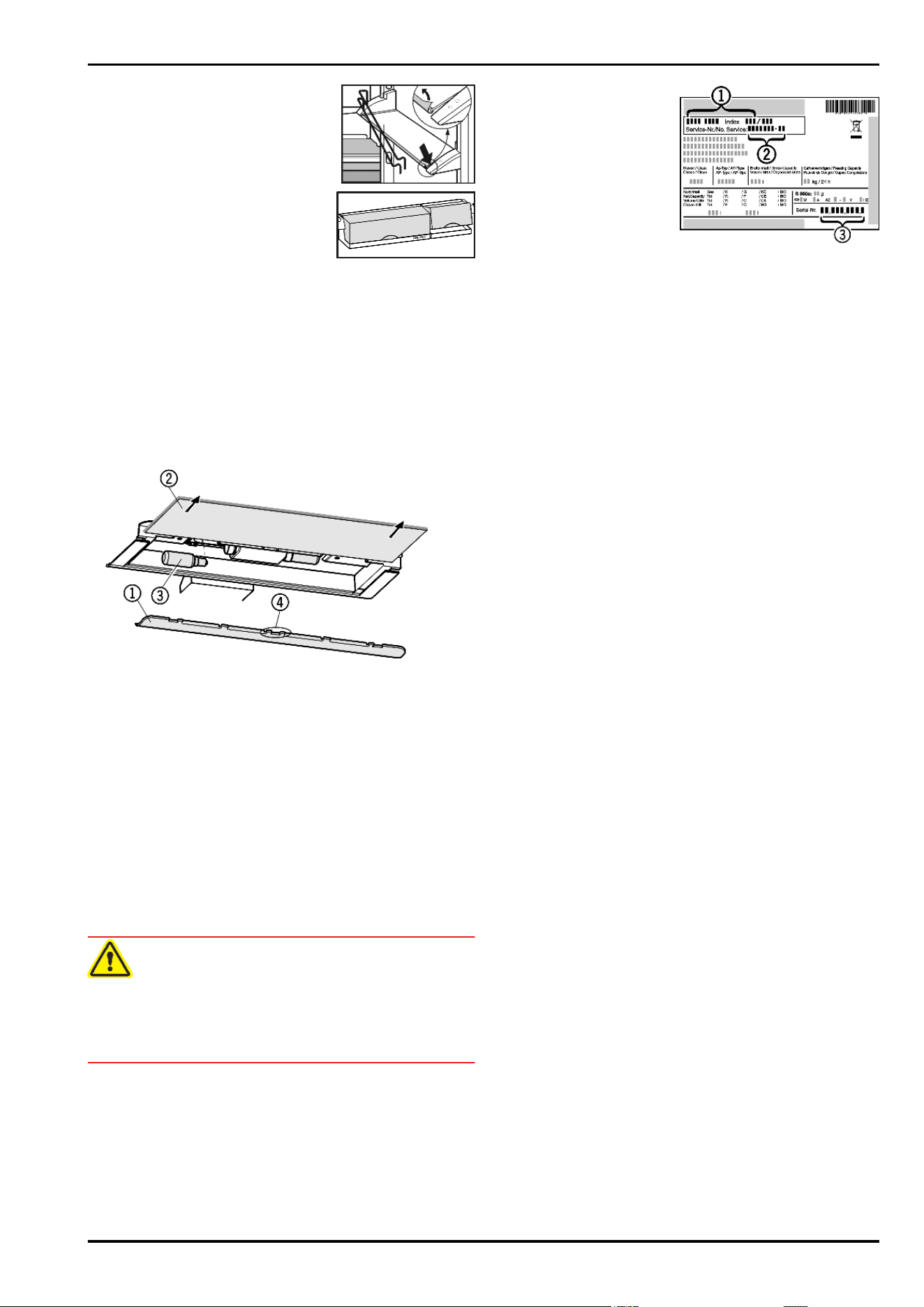
Fig. 4
u
Open the door.
NOTICE
Risk of damage!
If the door seal is damaged, the door may fail to close properly
and the cooling will be inadequate.
u
Do not damage the door seal with the screwdriver!
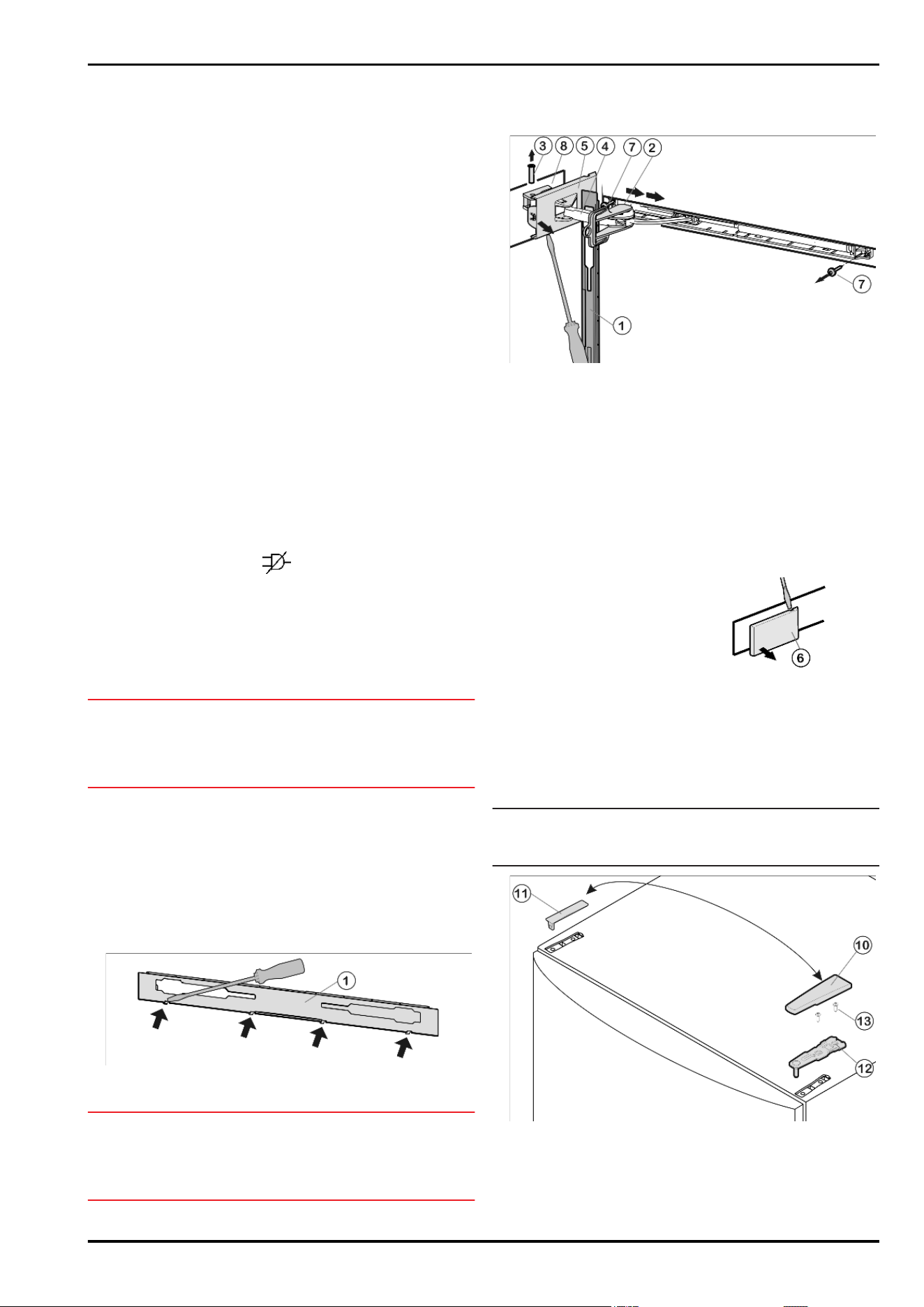
u
Disengage and remove the faceplate
Fig. 4 (1)
using a flat-
blade screwdriver.
w
The faceplate is attached over the soft stop bracket.
Fig. 5
u
Slide the faceplate forwards over the soft stop bracket
Fig. 5 (5)
in the direction of the appliance.
u
Snap the safety lock
Fig. 5 (3)
into the oblong hole.
w
The safety lock prevents the hinge from snap-closing.
u
Using a screwdriver, lift off the cover
Fig. 5 (2)
from the outside
and remove it in an outward direction.
u
If necessary, tip the appliance backwards with the assistance
of a second person.
u
Press the pin
Fig. 5 (4)
out from underneath.
u
Press the soft stop bracket
Fig. 5 (5)
towards the door.
u
Remove the faceplate
Fig. 5 (1)
.
u
Unscrew the entire soft stop unit (2 Torx 15)
Fig. 5 (6)
.
u
Pull the soft stop unit out a little, push it in the direction of the
handle side and swing it out.
u
Set the soft stop unit aside.
4.1.2 Detaching the door
Note
u
Remove any food from the door racks before removing the
door, so that no food falls out.
Controls and displays
4
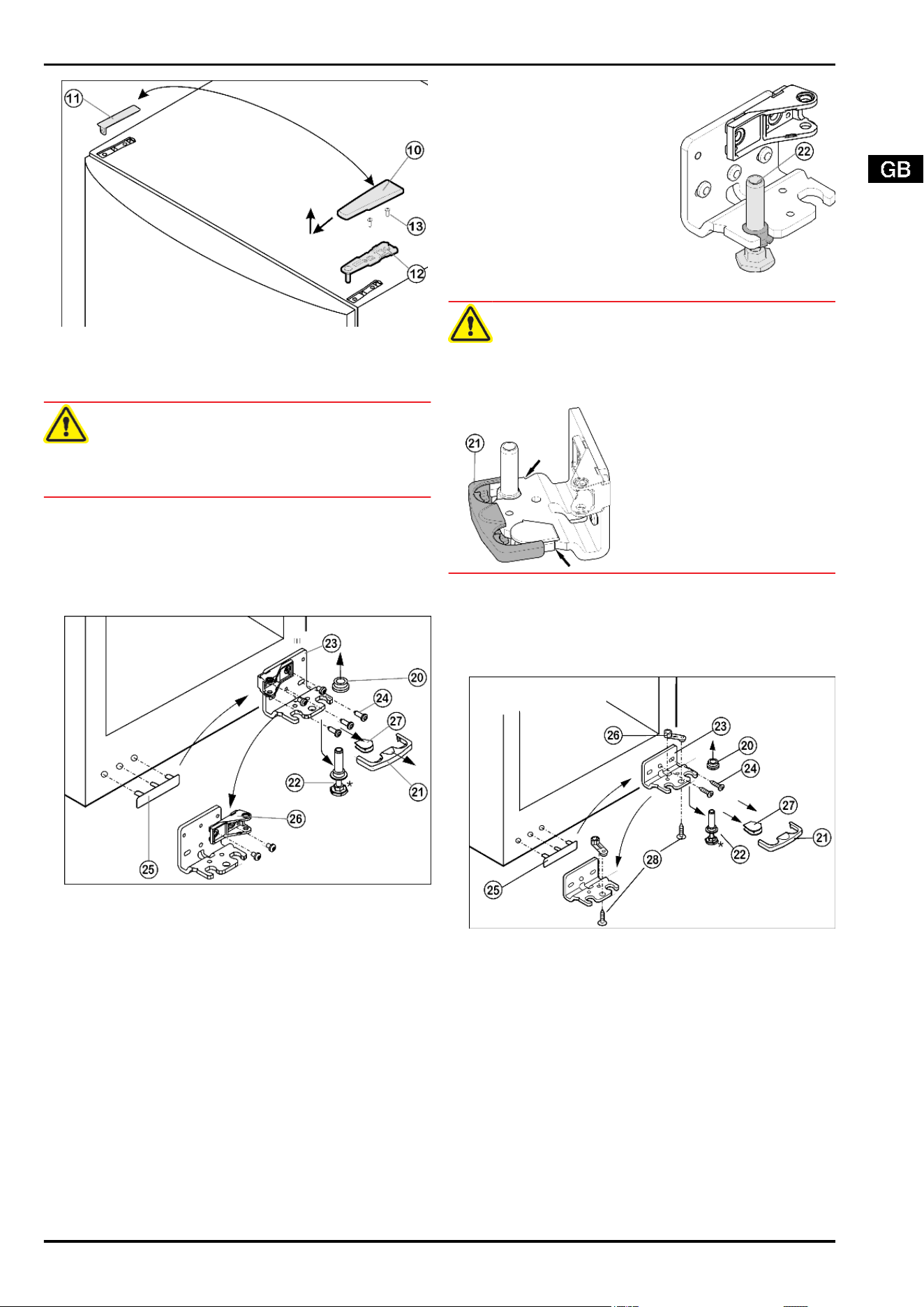
Fig. 6
u
Close the door.
u
Pull off the cover
Fig. 6 (10)
forwards and upwards.
u
Lift off the cover
Fig. 6 (11)
.
CAUTION
Risk of injury if the door tips!
u
Take good hold of the door.
u
Set down the door carefully.
u
Unscrew the upper turn hinge
Fig. 6 (12)
(2 Torx 25)
Fig. 6 (13)
and raise it for removal.
u
Lift up the door and set it aside.
4.1.3 Changing bearing parts*
For appliances with soft stop mechanism.*
Fig. 7
u
Draw the safety lock
Fig. 7 (21)
forwards for removal.
u
Remove the cover
Fig. 7 (27)
.*
u
Turn the adjustable-height foot
Fig. 7 (22)
all the way in.
u
If necessary, tip the appliance back a little with the assistance
of a second person for removal of the bearing pin.
u
Pull out the bearing pin
Fig. 7 (22)
downwards and forwards.
In so doing, pay attention to the hinge bush
Fig. 7 (20)
.
u
Unscrew the turn hinge
Fig. 7 (23)
(3 Torx 25)
Fig. 7 (24)
.
u
Carefully lift off and transfer the cover on the handle side
Fig. 7 (25)
.
u
Screw the turn hinge
Fig. 7 (23)
firmly into place on the new
hinge side using a cordless screwdriver.
u
Unscrew the bearing part
Fig. 7 (26)
, turn it 180° and screw it
down again.
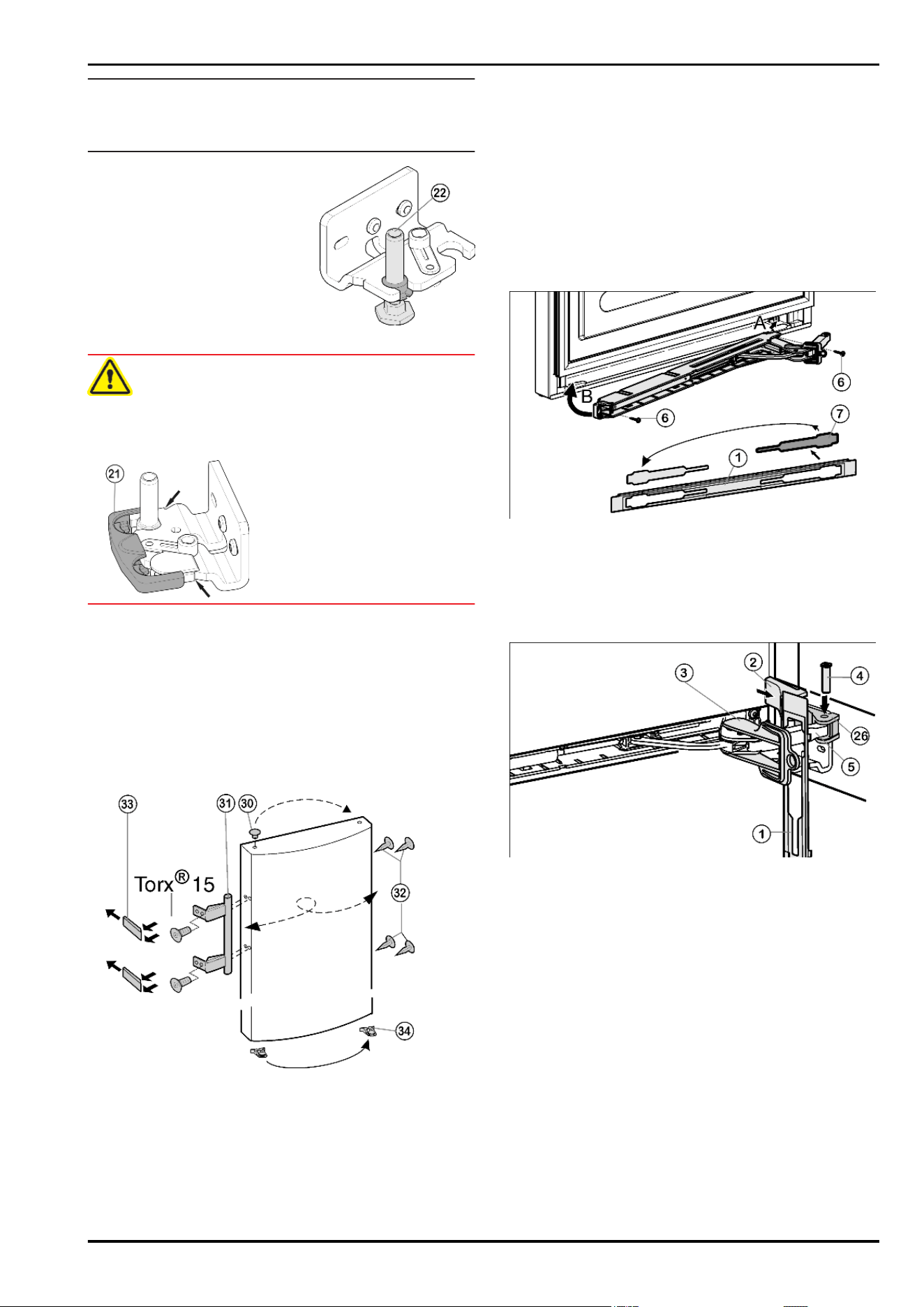
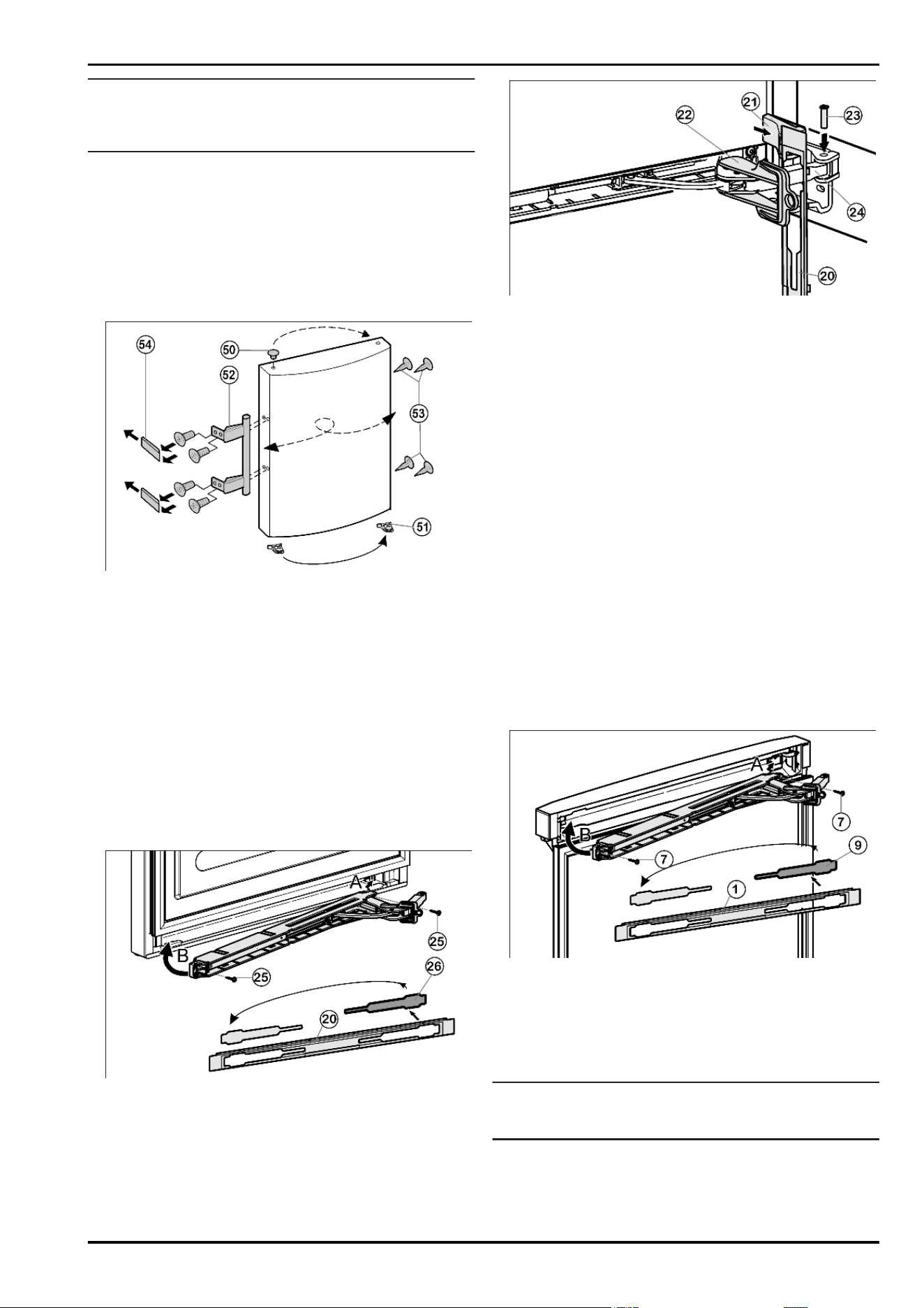
u
Tip the appliance back a lit-
tle again and re-insert the
bearing pin
Fig. 8 (22)
. The
notch has to point forwards.
u
Place the cover
Fig. 7 (27)
on the opposite side.*
Fig. 8
CAUTION
Risk of injury if the door tips!
u
The safety lock
(21)
has to engage with the turn hinge at the
side so that the bearing pin and therefore the door are se-
cured.
u
u
Snap the safety lock
(21)
onto the turn hinge again.
u
Put on the hinge bush
Fig. 7 (20)
.
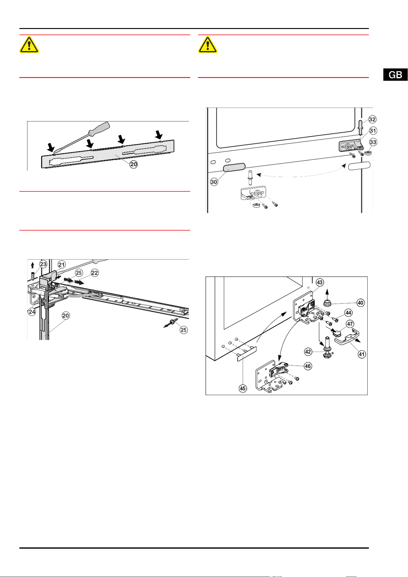
4.1.4 Changing bearing parts*
For appliances without soft stop mechanism.*
Fig. 9
u
Draw the safety lock
Fig. 9 (21)
forwards for removal.
u
Remove the cover
Fig. 9 (27)
.*
u
Fully retract the adjustable-height foot
Fig. 9 (22)
.
u
If necessary, tip the appliance back a little with the assistance
of a second person for removal of the bearing pin.
u
Pull out the bearing pin
Fig. 9 (22)
downwards and forwards.
In so doing, pay attention to the hinge bush
Fig. 9 (20)
.
u
Unscrew the turn hinge
Fig. 9 (23)
(2 Torx 25)
Fig. 9 (24)
.
u
Unscrew the bearing part
Fig. 9 (26)
(1 Torx 25),
Fig. 9 (28)
transfer it to the opposite hole in the turn hinge and screw it
down again.
u
Carefully lift off and transfer the cover
Fig. 9 (25)
on the handle
side.
u
Screw down the turn hinge
Fig. 9 (23)
on the new hinge side,
possibly with the aid of a cordless screwdriver, through the
outer oblong hole and round hole.
Putting into operation
5
Note
u
If necessary, e.g. to make up for any unevenness in the floor,
the second oblong hole can be used instead of the round hole
for the screw fitting.
u
Tip the appliance back a little
again and re-insert the bear-
ing pin
Fig. 10 (22)
. The
notch has to point forwards.
u
Place the cover
Fig. 9 (27)
on
the opposite side.*
Fig. 10
CAUTION
Risk of injury if the door tips!
u
The safety lock
(21)
has to engage with the turn hinge at the
side so that the bearing pin and therefore the door are se-
cured.
u
u
Snap the safety lock
(21)
onto the turn hinge again.
u
Put on the hinge bush
Fig. 9 (20)
.
4.1.5 Transferring the handle
For appliances without soft stop mechanism.
u
Disengage the spring clip
Fig. 11 (34)
from the door and trans-
fer it to the new hinge side.*
For all appliances:
u
Lift the stopper
Fig. 11 (30)
out of the door bearing bush and
transfer it.
Fig. 11
u
Detach door handle
Fig. 11 (31)
, stoppers
Fig. 11 (32)
and
pressure plates
Fig. 11 (33)
and transfer to the opposite side.
u
When fitting the pressure plates at the opposite side, pay at-
tention that they engage properly.
4.1.6 Fitting the lower door
u
Place the door from above onto the lower bearing pin
Fig. 9 (22)
.
u
Close the door.
u
Insert the upper turn hinge
Fig. 6 (12)
in the door on the new
hinge side.
u
Screw down the upper turn hinge
Fig. 6 (12)
(2 Torx 25)
Fig. 6 (13)
. Possibly make preliminary holes with a bradawl or
use a cordless screwdriver.
u
Snap the cover
Fig. 6 (10)
and cover
Fig. 6 (11)
into place at
the opposite side.
4.1.7 Fitting the soft stop unit*
For appliances with soft stop mechanism.
For appliances without soft stop mechanism continue with
point: Aligning the door.
Fig. 12
u
Remove the cover
Fig. 12 (7)
from the faceplate
Fig. 12 (1)
and re-insert it at the other side.
u
Engage the soft stop unit with the joint pointing to the hinge
side (A) and swivel into place (B).
w
The screw holes at the left and right have to register.
u
Screw down the soft stop unit (2 Torx 15)
Fig. 12 (6)
.
Fig. 13
u
Attach the faceplate
Fig. 13 (1)
to the soft stop bracket so that
the catches face forwards and the front faces the appliance.
u
Draw the soft stop bracket
Fig. 13 (5)
towards the bearing
part
Fig. 13 (26)
and re-insert the pin
Fig. 13 (4)
from above
so that the square sits in the recess.
u
Attach and engage the cover
Fig. 13 (2)
.
w
Pay attention that the cover fits properly so that the door closes
properly and the pin is secured.
u
Twist the safety lock
Fig. 13 (3)
for removal.
u
Snap thefaceplate
Fig. 13 (1)
onto the door.
u
Close the door.
4.1.8 Aligning the door
For appliances with soft stop mechanism.
u
Undo the middle screw on the lower turn hinge
Fig. 9 (23)
.*
For appliances without soft stop mechanism.
u
Transfer the middle screw on the lower turn hinge
Fig. 9 (23)
into the free oblong hole.*
For all appliances:
u
Align the door to the appliance housing by way of the two ob-
long holes in the lower turn hinge
Fig. 9 (23)
.
Putting into operation
6
u
Tighten the screws.
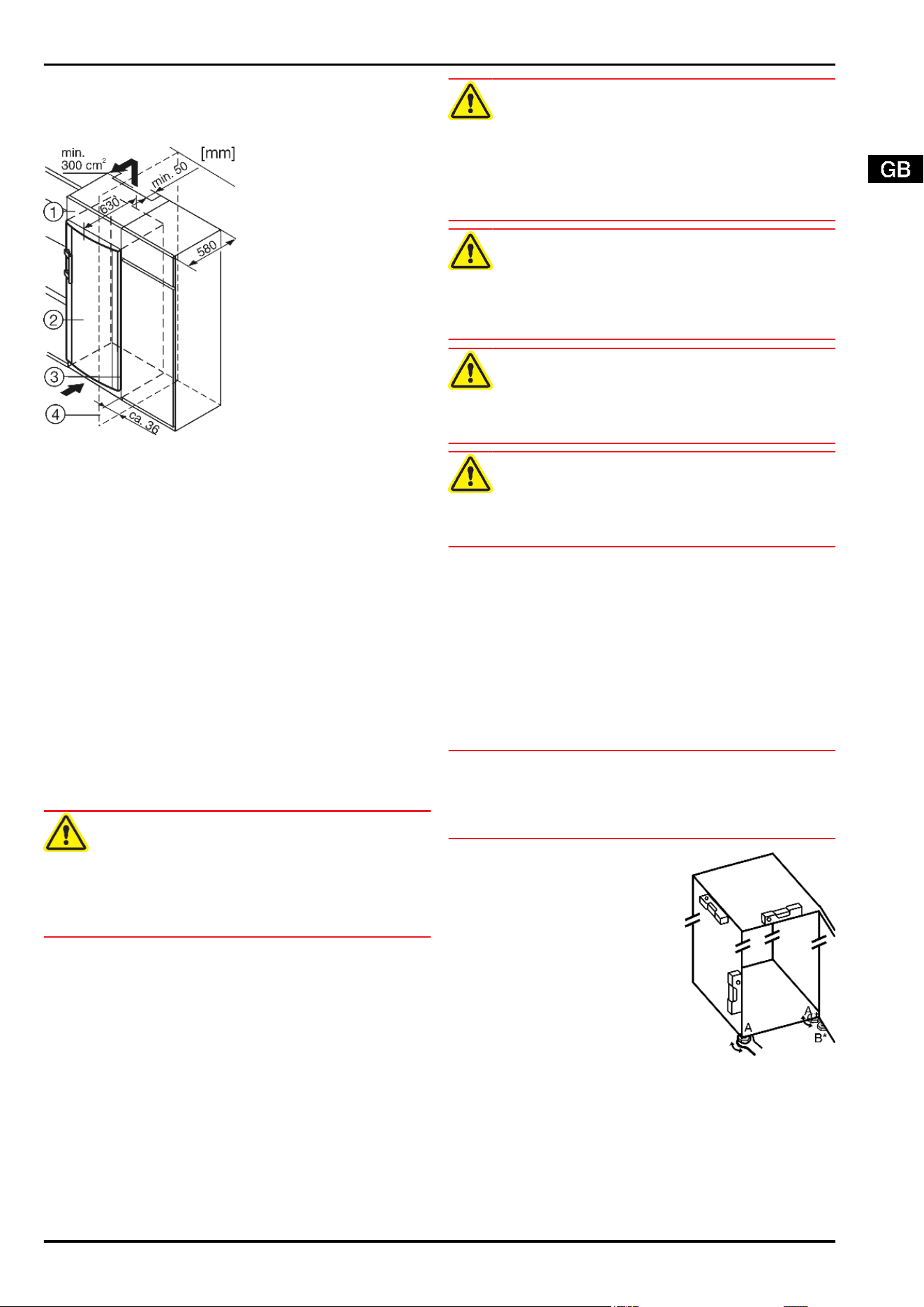
4.2 Insertion into a row of kitchen units
Fig. 14
(1) Stack cabinet (3) Kitchen cabinet
(2) Appliance (4) Wall
When inserting the appliance into a row of standard kitchen units
(max. depth 580 mm), the appliance can be installed directly next
to the kitchen unit
Fig. 14 (3)
. The appliance door projects relative
to the front of the kitchen unit by 34 mm at the side and by
50 mm in the middle of the appliance. It can be opened and
closed perfectly as a result.
Important for the ventilation:
-
At the back of the stack cabinet there has to be a ventilation
duct of at least 50 mm depth throughout the width of the stack
cabinet.
-
The ventilation space under the ceiling has to be at least
300 cm
2
.
-
The larger the ventilation space, the more energy-saving the
appliance is in operation.
If the appliance is installed with the hinges next to a wall
Fig. 14 (4)
, the distance between appliance and wall has to be at
least 36 mm. This corresponds to the projection of the handle
when the door is open.
4.3 Transporting the appliance
CAUTION
Risk of injury and danger of damage as a result of incorrect trans-
port!
u
Transport the appliance in a packed condition.
u
Transport the appliance upright.
u
Do not transport the appliance without assistance.
4.4 Installing the appliance
In the event that the appliance is damaged, contact the supplier
immediately before connecting to the mains.
The floor at the site must be flat and level.
Do not install the appliance in a location where it is exposed to
direct radiation of the sun, next to a cooker, heater and similar.
Always install the appliance directly against the wall.
Do not install the appliance without assistance.
Standard EN 378 specifies that the room in which you install your
appliance must have a volume of 1 m
3
per 8 gof R 600a refrigerant
used in the appliance. If the room in which the appliance is in-
stalled is too small, a flammable gas-air mixture may form in the
event of a leakage in the refrigeration circuit. The quantity of re-
frigerant used in your appliance is indicated on the type plate on
the inside of the appliance.
WARNING
Fire hazard due to dampness!
If live parts or the mains lead become damp this may cause short
circuits.
u
The appliance is designed for use in enclosed areas. Do not
operate the appliance outdoors or in areas where it is exposed
to splash water or damp conditions.
WARNING
Fire hazard due to refrigerant!
The refrigerant R 600a is environmentally friendly but flammable.
Escaping refrigerant may ignite.
u
Do not damage the piping of the refrigeration circuit.
WARNING
Fire hazard and danger of damage!
u
Do not place appliances emitting heat e.g. microwaves, toast-
ers etc. on the appliance!
WARNING
Fire hazard and risk of damage due to blocked ventilation grille!
u
Always keep the ventilation grille free. Always ensure that the
appliance is properly ventilated.
u
Detach the connecting cable from the rear of the appliance,
removing the cable holder at the same time because other-
wise there will be vibratory noise!
u
Remove the protective film from the outside of the appli-
ance.*
u
Evenly apply an agent for care of stainless steel, wiping in the
direction of the grain.*
w
Subsequent cleaning becomes easier as a result.*
u
Remove the protective film from the decorative trims.
u
Remove all transit supports.
u
Dispose of packaging material. See section on packaging dis-
posal.
NOTICE
Risk of damage due to condensate!
If your appliance is not a Side-by-Side (SBS) appliance:
u
do not install the appliance directly alongside a further refrig-
erator/freezer.
u
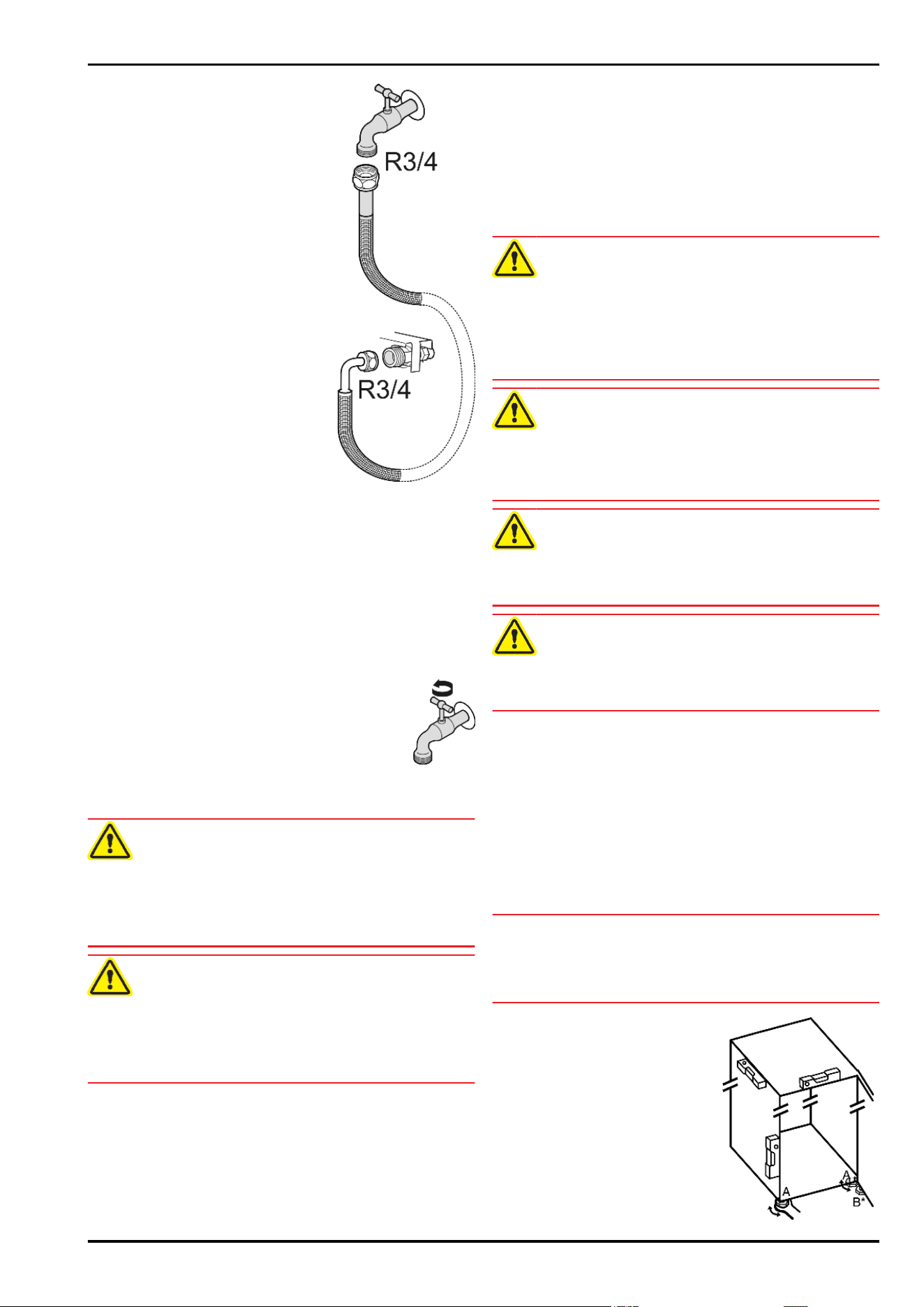
Align the appliance so that it stands
firmly and on a level by applying the
accompanying spanner to the ad-
justable-height feet (A) and using a
spirit level.
u
Then support the door: Extend the
adjustable foot at the turn hinge (B)
until it rests on the floor and then
make a further 90° turn.
When a Side-by-Side appliance (S…) is fitted together with a
second appliance (as a SBS combination):
u
Proceed according to the Side-by-Side combined fridge-
freezer installation instructions. (Accessories bag of the SBS
freezer/appliance with freezer compartment)
If the appliance is installed in a very damp environment, conden-
sate may form on the outside of the appliance.
u
Always see to good ventilation at the installation site.
Putting into operation
7
4.5 Disposing of packaging
WARNING
Danger of suffocation due to packing material and plastic film!
u
Do not allow children to play with packing material.
The packaging is made of recyclable materials:
-
corrugated board/cardboard
-
EPS moulded parts
-
polythene bags and sheets
-
polypropylene straps
u
Take the packaging material to an official collecting point.
4.6 Connecting the appliance
NOTICE
Risk of damage to the electronic control system!
u
Do not use stand-alone inverters (conversion of d.c. to a.c./
three-phase) or energy saving plugs.
WARNING
Fire and overheating hazard!
u
Do not use extension cables or multiple socket outlets.
The type of current (alternating current) and voltage at the instal-
lation site have to conform with the data on the type plate (see
section on description of appliance and equipment).
Connect the appliance only with a properly installed
socket outlet with earthing contact. The socket outlet
must be fused with 10 A or higher.
It must be easily accessible so that the appliance can
be quickly disconnected from the supply in an emer-
gency.
u
Check the electrical connection.
u
Clean the appliance. More information on this is in the section
on cleaning.
u
Plug in the power plug.
4.7 Switching on the appliance
u
Press On/Off button
Fig. 3 (3)
.
w
The temperature display indicates the current temperature.
w
The interior light is on when the door is open.
5 Control
5.1 Saving energy
u
Always pay attention to good ventilation.
u
Keep the time the appliance is open to a minimum.
u
Store food logically.
u
First cool warm food to room temperature before storing it .
Accumulated dust increases the energy con-
sumption:
u
Once a year, dust the refrigerating unit to-
gether with the metal grille of the heat ex-
changer at the back of the appliance.
5.2 Brightness of the temperature dis-
play
You can adjust the brightness of the temperature display to the
light conditions of the room in which the appliance is installed.
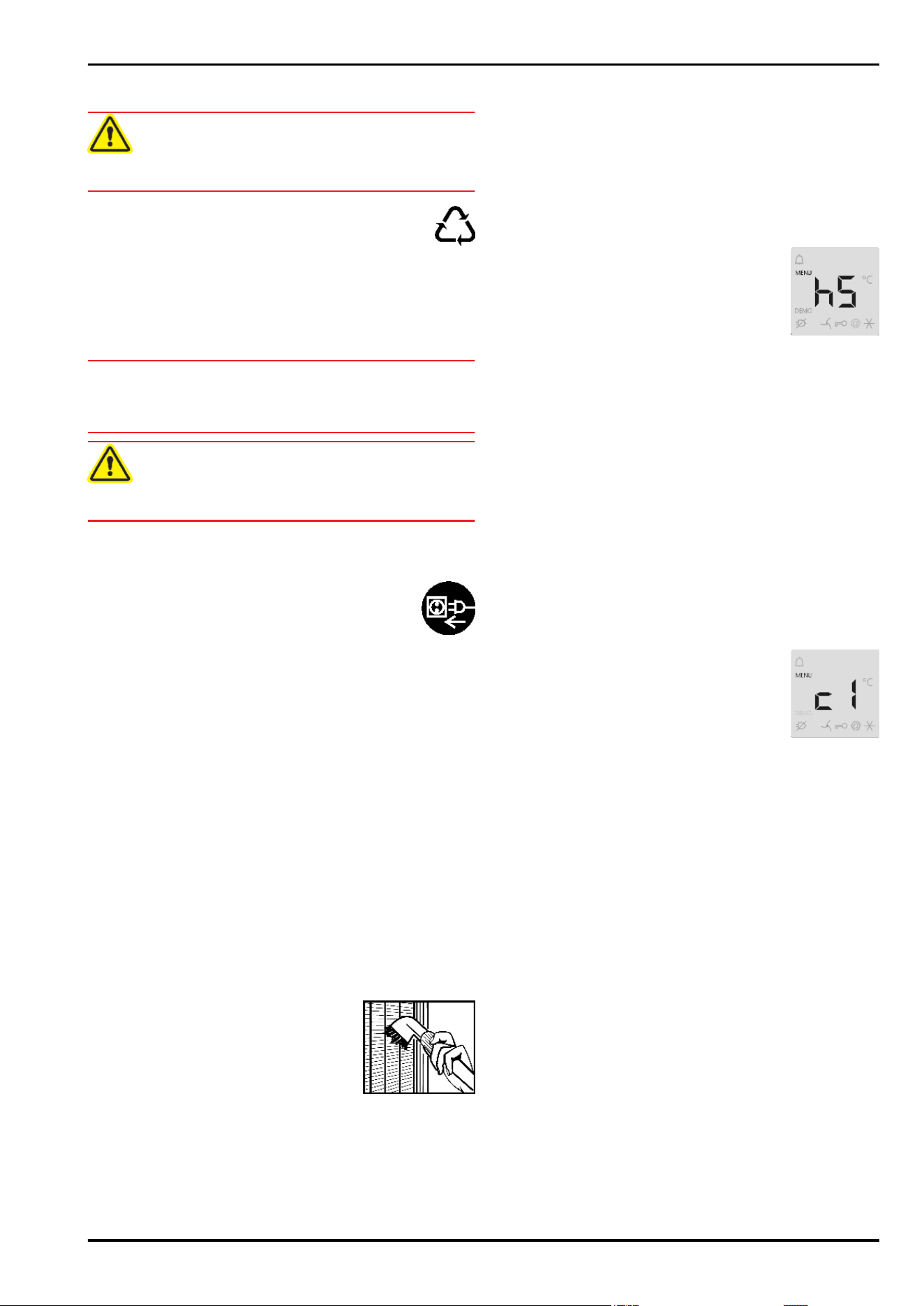
5.2.1
Adjusting the brightness
The brightness is adjustable between h0 (no illumination) and
h5 (maximum luminosity).
u
To activate the setting mode: press SuperCool button
Fig. 3 (2)
for about 5s.
w
The menu symbol
Fig. 3 (5)
shines. The display indicates c.
u
Using the Up setting button
Fig. 3 (7)
and Down setting but-
ton
Fig. 3 (6)
, select h.
u
To confirm: briefly press the SuperCool button
Fig. 3 (2)
.
u
To set the display brighter: press the Up set-
ting button
Fig. 3 (7)
.
u
To set the display darker: press the Down
setting button
Fig. 3 (6)
.
u
To confirm: briefly press the SuperCool but-
ton
Fig. 3 (2)
.
w
The brightness is adjusted to the new value.
u
To deactivate the setting mode: press the On/Off button
Fig. 3 (3)
.
-or-
u
Wait for 5 minutes.
w
The temperature is indicated again in the temperature display.
5.3 Child proofing
The child-proofing function enables you to make sure that the
appliance is not inadvertently switched off by playing children.
5.3.1 Setting the child lock function
u
To activate the setting mode: press SuperCool button
Fig. 3 (2)
for about 5 s.
w
The display indicates c.
w
The menu symbol
Fig. 3 (5)
shines.
u
Briefly press the SuperCool button
Fig. 3 (2)
to confirm.
When c1 is indicated in the display:
u
to activate the child lock, briefly press the Su-
perCool button
Fig. 3 (2)
.
w
The child lock symbol
Fig. 3 (12)
shines. c flashes in the dis-
play.
When c0 is indicated in the display:
u
to deactivate the child lock, briefly press the SuperCool but-
ton
Fig. 3 (2)
.
w
The child lock symbol
Fig. 3 (12)
goes out. c flashes in the
display.
u
To deactivate the set-up mode: press On/Off button
Fig. 3 (3)
.
-or-
u
Wait for 5 minutes.
w
The temperature is indicated again in the temperature display.
5.4 Door alarm
If the door is open longer then 60 s, the audible alarm sounds.
The audible alarm is automatically silenced when the door is
closed.
5.4.1 Muting the door alarm
The audible alarm can be muted when the door is open. The
sound switch-off function is active as long as the door is left open.
u
Press alarm button
Fig. 3 (1)
.
5.5 Refrigerator compartment
The natural circulation of air in the refrigerator compartment re-
sults in zones differing in temperature. It is coldest directly above
Control
8
the plate separating off the BioFresh zone and at the rear wall. It
is warmest at the top front of the compartment and in the door.
5.5.1 Food refrigeration
Note
The energy consumption increases and the cooling performance
decreases if the ventilation is inadequate.
u
Always keep the air slits of the fan free.
u
Place butter, eggs and preserves in the upper area and in the
door. (see also the section onthe appliance at a glance)
u
Use recyclable plastic, metal, aluminium and glass containers
and cling film for wrapping.
For appliances from 1216 mm high:*
u
Use the front area of the refrigerator compartment floor only
for briefly putting down cooled products, e.g. when rearrang-
ing and sorting. However do not leave cooled products there
otherwise they may be pushed back or tipped over when the
door is closed.
u
Do not store food too close together to enable good air circu-
lation.
u
To safeguard bottles from tipping over: move the bottle holder.
At the base of the refrigerator compartment, the integrated bottle
shelf or alternatively the glass shelf can be used:
u
To use the bottle shelf:
store the glass shelf com-
pactly under the bottle
shelf.
u
Place the bottles with the
base pointing backwards
facing the rear wall.
If the bottles project be-
yond the bottle shelf:
u
set the lower door rack
one position higher.
5.5.2 Setting the temperature in the refrigerator
compartment
The temperature can be set from 9 °C to 3 °C, the recommended
temperature is 5 °C.
u
For a higher temperature setting: press Up button
Fig. 3 (7)
.
u
For a lower temperature setting: press Down button
Fig. 3 (6)
.
w
The first time the button is pressed, the value set so far is in-
dicated in the temperature display.
u
To change the temperature in 1 °C steps: briefly press the
button.
u
To change the temperature continuously: hold down the but-
ton.
w
The value is displayed flashing during the setting operation.
w
The actual temperature is displayed about 5 s after the last
press of a button. The temperature slowly adjusts to the new
value.
5.5.3 SuperCool
With SuperCool you switch to the highest cooling performance
to reach lower cooling temperatures. Use SuperCool to rapidly
cool large amounts of food.
The SuperCool function uses slightly more energy.
Cooling with SuperCool
u
Briefly press SuperCool button
Fig. 3 (2)
.
w
The SuperCool symbol
Fig. 3 (11)
lights up in the display.
w
The cooling temperature drops to the coldest value. Super-
Cool is activated.
w
SuperCool is automatically deactivated after 6 to12 hours The
appliance continues to operate in the energy-saving, normal
mode.
To prematurely deactivate SuperCool
u
Briefly press SuperCool button
Fig. 3 (2)
.
w
The SuperCool symbol
Fig. 3 (11)
goes out in the display.
w
SuperCool is deactivated.
5.5.4 Holiday mode
The holiday mode saves energy and prevents odour from occur-
ring when the door of the refrigerator compartment stays closed
for a lengthy period.
Activating the holiday mode
u
Remove all the food from the refrigerator and
BioFresh compartment, otherwise they will
perish..
u
Press the holiday button
Fig. 3 (8)
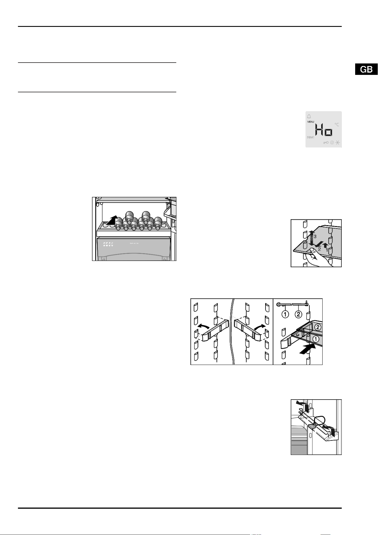
for 3 sec.
w
The holiday mode is activated. The display indicates Ho.
Deactivating the holiday mode
u
Briefly press the holiday button
Fig. 3 (8)
.
w
The holiday mode is deactivated.
w
The current cooling temperature is indicated in the display.
5.5.5 Relocating the shelves
The shelves have stops preventing them from being unintention-
ally pulled out.
u
Lift the shelf and draw it out forwards.
u
Insert shelf with the raised edge pointing upwards at the back.
w
The food does not freeze onto the rear wall.
5.5.6 Using the sectioned shelf
Fig. 15
u
The glass shelf with stop face (2) has to be at the back.
5.5.7 Moving the storage rack
u
Remove storage rack according to il-
lustration.
The boxes can be removed and placed on the table as a single
unit.
Only one box or both boxes can be used. If particularly tall bottles
are to be stored, attach only the wide box above the bottle rack.
Three small boxes are available through the customer service as
optional equipment instead of one wide and one small box.
Control
9
u
Re-positioning the boxes: Lift them for
removal and re-position them as re-
quired.
u
To detach lid: Open 90° and raise to
disengage.
5.5.8 Removing the bottle holder
u
Always take hold of the bottle holder on
the plastic part.
5.6 BioFresh compartment
The BioFresh compartment allows some types of fresh food to
be stored up to three times longer than in conventional refriger-
ators, without compromising quality.
For food with an indicated best before date, the date specified
on the packaging always applies.
5.6.1 HydroSafe
The HydroSafe at the moist setting is suited for storing unwrap-
ped salad, vegetables and fruit with high inherent moisture.
When the drawer is well filled, a dewy climate with up to 90%
humidity is established. The humidity in the compartment de-
pends on the moisture content of the food stored and on the
opening frequency. You can set the humidity yourself.
5.6.2 DrySafe
The DrySafe is suitable for storing dry or wrapped food (e.g. dairy
products, meat, fish, sausages). A relatively dry storage climate
is established here.
5.6.3 Storing food
Note
u
Vegetables sensitive to cold, such as cucumbers, aubergines,
semi-ripe tomatoes, zucchinis and all tropical fruits sensitive
to cold, do not belong in the BioFresh compartment.
u
To prevent food spoilage due to transfer of germs: Store un-
wrapped animal and vegetable products separate from one
another in the drawers. This also applies to different sorts of
meat.
If food has to be stored together due to lack of space:
u
wrap the food.
5.6.4 Storage times
Standard values for storage time at low humidity
Butter up to 90 days
Hard cheese up to 110 days
Milk up to 12 days
Sausage, cold meat up to 9 days
Poultry up to 6 days
Pork up to 7 days
Standard values for storage time at low humidity
Beef up to 7 days
Game up to 7 days
Note
u
Please note that protein-rich food deteriorates faster, i.e.
shellfish and crustaceans deteriorate faster than fish, fish fast-
er than meat.
Standard values for storage time at high humidity
Vegetables, salad
Artichokes up to 14 days
Celery up to 28 days
Cauliflower up to 21 days
Broccoli up to 13 days
Chicory up to 27 days
Lamb's lettuce up to 19 days
Peas up to 14 days
Kale up to 14 days
Carrots up to 80 days
Garlic up to 160 days
Kohlrabi up to 55 days
Lettuce up to 13 days
Herbs up to 13 days
Leek up to 29 days
Mushrooms up to 7 days
Radishes up to 10 days
Brussels sprouts up to 20 days
Asparagus up to 18 days
Spinach up to 13 days
Savoy cabbage up to 20 days
Fruit
Apricots up to 13 days
Apples up to 80 days
Pears up to 55 days
Blackberries up to 3 days
Dates up to 180 days
Strawberries up to 7 days
Figs up to 7 days
Blueberries up to 9 days
Raspberries up to 3 days
Currants up to 7 days
Sweet cherries up to 14 days
Kiwis up to 80 days
Peaches up to 13 days
Plums up to 20 days
Cranberries up to 60 days
Rhubarb up to 13 days
Control
10
Standard values for storage time at high humidity
Gooseberries up to 13 days
Grapes up to 29 days
5.6.5 Adjusting the temperature in the BioFresh
compartment
The temperature is automatically regulated to between 0 °C and
3 °C, the recommended temperature is 1 °C.
You can adjust the temperature slightly colder or warmer. The
temperature can be adjusted from b1 (coldest temperature) to
b9 (warmest temperature). The presetting is b5. At the b1 to b4
settings the temperature may drop below 0 ° C and therefore the
food may freeze slightly.
Note
for testing institutes: If temperatures below 3 °C are to be
reached in the refrigerator compartment:
u
set the temperature in the BioFresh compartment to b1-b4.
u
To activate the setting mode: press the SuperCool button
Fig. 3 (2)
for about 5 s.
w
The menu symbol
Fig. 3 (5)
shines. The temperature display
indicates c.
u
Using the Up setting button
Fig. 3 (7)
and Down setting but-
ton,
Fig. 3 (6)
select b.
u
To confirm: briefly press the SuperCool button
Fig. 3 (2)
.
u
For a warmer temperature adjustment: press Up setting but-
ton
Fig. 3 (7)
.
u
For a colder temperature adjustment: press Down setting but-
ton
Fig. 3 (6)
.
u
To confirm: press SuperCool button
Fig. 3 (2)
.
w
The temperature slowly adjusts to the new
value.
u
To deactivate the setting mode: press the On/Off button
Fig. 3 (3)
.
-or-
u
Wait for 5 minutes.
w
The temperature is indicated again in the temperature display.
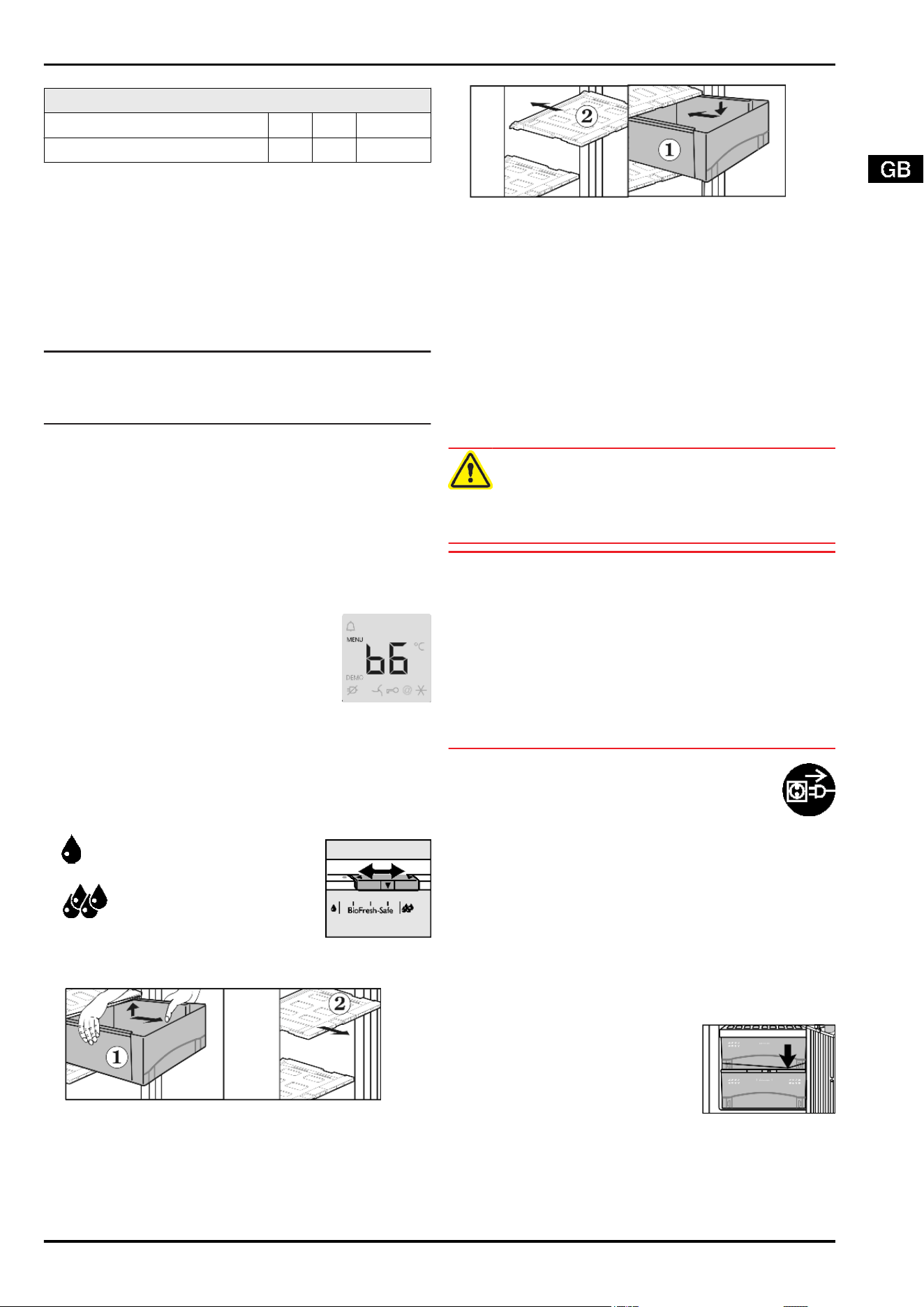
5.6.6 Setting the humidity in the HydroSafe
u
Low humidity: move the regulator to the
left.
u
High humidity: move the regulator
to the right.
5.6.7 Drawers
Fig. 16
u
Pull out drawers
Fig. 16 (1)
to the limit.
u
Then raise the drawer at the back, pull it forwards and lift it.
w
In the case of the bottom drawer, the drawer lock is additionally
released and the drawer can be removed.
u
Disengage drawer cover
Fig. 16 (2)
with humidity controller of
removed drawers by lifting and draw it forwards for removal.
Fig. 17
u
To insert drawer cover
Fig. 17 (2)
: Insert mouldings of the
drawer cover into the rear holders from underneath and snap
into the holder at the front.
u
Place drawers
Fig. 17 (1)
on the rails and slide them all the
way in until the drawer audibly snaps into place.
w
In the case of the bottom drawer, the drawer lock additionally
engages and the vegetable drawer sits firmly on the telescopic
rails.
6 Maintenance
6.1 Cleaning the appliance.
Before cleaning:
CAUTION
Risk of injury and damage as a result of hot steam!
Hot steam may damage the surfaces and cause burns.
u
Do not use any steam cleaners!
NOTICE
Incorrect cleaning damages the appliance!
u
Do not use cleaning agents in concentrated form.
u
Do not use any scouring or abrasive sponges or steel wool.
u
Do not use any cleaning agents containing sand, chloride,
chemicals or acid.
u
Do not use chemical solvents.
u
Do not damage or remove the type plate on the inside of the
appliance. It is important for the customer service.
u
Do not pull off, bend or damage cables or other components.
u
Do not allow any cleaning water to enter the drain channel,
ventilation grille or electrical parts.
u
Empty the appliance.
u
Pull out the power plug.
- Use soft cleaning cloths and a multi-purpose clean-
ing agent with neutral pH value.
- Only use food compatible cleaning and care agents
on the inside of the appliance.
Outside surfaces and interior:
u
Clean the plastic surfaces, outside and inside, by hand using
lukewarm water and a little washing-up liquid.
Clean stainless steel surfaces with a standard stainless steel
cleaning agent. Darker areas at the beginning and quite an in-
tensive colour of the stainless steel surface are normal.*
u
Do not apply cleaners to glass or plastic surfaces so as not to
scratch them.*
u
To clean stainless steel surfaces: evenly apply an agent for
care of stainless steel, wiping in the direction of the grain.*
u
To clean the drain opening: remove
any deposits with a fine instrument,
e.g. a cotton bud.
Items of equipment:
u
Clean items of equipment by hand with lukewarm water and
a little washing-up liquid.
u
For cleaning, remove the support rails for the half-sized glass
shelves.
Maintenance
11
u
To dismantle the shelves: remove the
trims and side parts.
u
To dismantle the storage rack: re-
move the protective film from the dec-
orative trims.
u
Lift out the boxes and lift the covers
for removal.
After cleaning:
u
Wipe dry the appliance and items of equipment.
u
Connect the appliance and switch it on again.
u
Put the food back inside.
6.2 Changing the interior light with bulb*
Bulb data
max. 25 W
Fitting: E14
Type of current and voltage must conform with the details on
the type plate
Fig. 18
u
Switch off the appliance.
u
Pull out the power plug or switch off the fuse.
u
To remove the cover
Fig. 18 (1)
: put your finger behind the
cover and disengage it.
u
Pull out the glass shelf
Fig. 18 (2)
.
u
Change the bulb
Fig. 18 (3)
.
u
Slide the glass shelf back in.
u
Attach the cover again, engage it at the right and left and pay
attention that the middle hook
Fig. 18 (4)
grips over the glass
shelf.
6.3 Customer service
First check whether you can correct the fault yourself by refer-
ence to the list in the section on troubleshooting. If this is not the
case, please contact the customer service whose address is giv-
en in the enclosed customer service list.
WARNING
Risk of injury if repair work is not carried out professionally!
u
Have any repairs to and intervention in the appliance and
mains power cable, which are not expressly mentioned in the
section on maintenance, carried out by the customer service
only.
u
Read the appliance
designation
Fig. 19 (1)
,
service No.
Fig. 19 (2)
and serial No.
Fig. 19 (3)
off the type
plate located inside the
appliance on the left-
hand side.
Fig. 19
u
Notify the customer service, specifying the fault, appliance
designation
Fig. 19 (1)
, service No.
Fig. 19 (2)
and serial No.
Fig. 19 (3)
.
w
This will help us to provide you with a faster and more accurate
service.
u
Keep the appliance closed until the customer service arrives.
w
The food will stay cool longer.
u
Pull out the mains plug (not by pulling the connecting cable)
or switch off the fuse.
7 Malfunction
Your appliance is designed and manufactured for a long life span
and reliable operation. If a malfunction nonetheless occurs dur-
ing operation, check whether it is due to a handling error. In this
case you will have to be charged for the costs incurred, even
during the warranty period. You may be able to rectify the follow-
ing faults yourself:
Appliance does not work.
→
The appliance is not switched on.
u
Switch on the appliance.
→
The power plug is not properly inserted in the wall socket.
u
Check power plug.
→
The fuse of the wall socket is not in order.
u
Check fuse.
The compressor runs for a long time.
→
The compressor switches to a low speed when little cold is
needed. Although the running time is increased as a result,
energy is saved.
u
This is normal in energy-saving models.
→
SuperCool is activated.
u
The compressor runs for longer in order to rapidly cool the
food. This is normal.
A bubbling and gurgling noise
→
This noise comes from the refrigerant flowing in the refriger-
ation circuit.
u
The sound is normal.
A quiet clicking noise
→
The noise is produced whenever the refrigeration unit (motor)
automatically switches on or off.
u
The sound is normal.
A hum. It is briefly a little louder when the refrigeration unit
(the motor) switches on.
→
The refrigeration increases automatically when fresh food
has just been placed in the appliance or the door has been
left open for a while.
u
The sound is normal.
→
The ambient temperature is too high.
u
See section on range of appliance use
A low hum
→
The sound is produced by air flow noise of the fan.
u
The sound is normal.
Vibratory noise
→
The appliance is not standing firmly on the floor. As a result,
adjoining units or objects are set into vibration by the running
refrigeration unit.
Malfunction
12
u
Move the appliance away a little and align it using the adjust-
able feet.
u
Move bottles and containers apart.
Flow sound at the soft stop mechanism.*
→
The noise is produced when the door is opened and closed.
u
The sound is normal.
The temperature display indicates: F0 to F9
→
There is a fault.
u
Contact the customer service. See the section on mainte-
nance.
DEMO shines in the temperature display.
→
The demo mode is activated.
u
Contact the customer service. See the section on mainte-
nance.
The outside surfaces of the appliance are warm.
→
The heat of the refrigeration circuit is used to prevent con-
densate from forming.
u
This is normal.
The temperature is not cold enough.
→
The door of the appliance is not properly closed.
u
Close the door of the appliance.
→
Insufficient ventilation.
u
Clear ventilation grilles.
→
The ambient temperature is too high.
u
See section on operating conditions of the appliance.
→
The appliance was opened too frequently or for too long.
u
Wait until the appliance reaches the required temperature it-
self. If not, contact the customer service. See the section on
maintenance.
→
The appliance is too close to a heat source.
u
See the section on installation.
The interior light is not on.
→
The appliance is not switched on.
u
Switch on the appliance.
→
The door was open longer than 15 min.
u
The interior light automatically switches off if the door has
been open for about 15 min.
→
If the interior light is not on but the temperature display is lit,
the bulb is faulty.
u
Change the bulb according to the section on maintenance.
→
The LED interior lighting is faulty or the cover is damaged:*
WARNING
*
Risk of injury due to electric shock!
Live parts are located under the cover.
u
Have the LED interior light changed or repaired only by the
customer service or by specialized personnel trained for the
purpose.
WARNING*
Danger of injury due to laser radiation, class 1M.
u
Do not look inside when the cover is open.
8 Decommissioning
8.1 Switching off the appliance
u
Press On/Off button
Fig. 3 (3)
for about 2 s.
w
The temperature display is dark.
8.2 Taking the appliance out of service
u
Empty the appliance.
u
Put the IceMaker in the cleaning position. (see section on
cleaning IceMaker)
u
Pull out the power plug.
u
Clean the appliance (see section on cleaning).
u
Leave the door open to prevent odour.
9 Disposing of the appliance
The appliance contains some reusable materials
and should be disposed of properly - not simply with
unsorted household refuse. Appliances which are no
longer needed must be disposed of in a professional
and appropriate way, in accordance with the current
local regulations and laws.
When disposing of the appliance, ensure that the refrigeration
circuit is not damaged to prevent uncontrolled escape of the re-
frigerant it contains (data on type plate) and oil.
u
Disable the appliance.
u
Pull out the plug.
u
Cut through the connecting cable.
Decommissioning
13

Disposing of the appliance
14
Operating and installation instructions
Multi-temperature wine cabinet with freezer compartment
15/08
7082644 - 00
SWTNes/WTNes ... 6
Contents
1 Appliance at a glance............................................ 2
1.1 Range of appliance use............................................ 2
1.2 Conformity................................................................ 2
1.3 Description of appliance and equipment.................. 2
1.4 External dimensions of the appliance....................... 3
1.5 Net@Home............................................................... 3
2 General safety information................................... 3
3 Controls and displays........................................... 3
3.1 Operating and control elements............................... 3
3.2 Temperature display................................................. 4
4 Putting into operation............................................ 4
4.1 Changing over the door hinges................................ 4
4.2 Insertion into a row of kitchen units........................... 7
4.3 Water connection..................................................... 7
4.4 Transporting the appliance....................................... 8
4.5 Installing the appliance............................................. 8
4.6 Disposing of packaging............................................ 9
4.7 Connecting the appliance......................................... 9
4.8 Switching on the appliance....................................... 9
5 Control.................................................................... 9
5.1 Saving energy.......................................................... 9
5.2 Brightness of the temperature display...................... 9
5.3 Child proofing........................................................... 9
5.4 Door alarm................................................................ 10
5.5 Temperature alarm................................................... 10
5.6 Freezer compartment............................................... 10
5.7 Wine zone................................................................ 12
6 Maintenance........................................................... 13
6.1 Replacing the activated charcoal filter...................... 13
6.2 Defrosting with NoFrost............................................ 13
6.3 Cleaning the appliance............................................. 13
6.4 Cleaning the IceMaker............................................. 13
6.5 Customer service..................................................... 14
7 Malfunction............................................................. 14
8 Decommissioning.................................................. 15
8.1 Switching off the appliance....................................... 15
8.2 Taking the appliance out of service.......................... 15
9 Disposing of the appliance................................... 15
The manufacturer works constantly on the further development
of all the types and models. Therefore please understand that we
have to reserve the right to make design, equipment and techni-
cal modifications.
To get to know all the benefits of your new appliance, please read
the information contained in these instructions carefully.
The instructions apply to several models. Differences may occur.
Text relating only to specific appliances is marked with an aster-
isk (*).
Instructions for action are marked with a
, the results of
action are marked with a .
1 Appliance at a glance
1.1 Range of appliance use
The appliance is designed for cooling wine, for freezing and stor-
ing food and for making ice.
The appliance was designed for household use. It is not intended
for commercial use, in particular it is not meant for laboratory
purposes and the like. There is the danger of malfunction.
The appliance is set to operate within specific ambient temper-
ature limits according to its climate rating. The correct climate
rating for your appliance is indicated on the type plate.
Note
u
Compliance with the ambient temperatures indicated is re-
quired, otherwise the cooling performance is reduced.
Climate rat-
ing
for ambient temperatures of
SN 10 °C to 32 °C
N 16 °C to 32 °C
ST 16 °C to 38 °C
T 16 °C to 43 °C
1.2 Conformity
The refrigerant circuit has been tested for leaks. The appliance
complies with current safety regulations and EC directives
2006/95/EC and 2004/108/EC.
As energy efficiency guidelines for multi-temperature wine cabi-
nets are not available, wine compartments are evaluated as cel-
lar temperature compartments for energy efficiency class allo-
cation.
1.3 Description of appliance and equip-
ment
Fig. 1
(1) Control panel (9) IceMaker
(2) LED lighting, replacea-
ble
(10) Freezer compartment
(3) Activated charcoal filter,
replaceable
(11) Freezer tray
(4) Wooden shelf, folding (12) Cold storage accumulators
(5) Label (13) VarioSpace
(6) Wooden shelf, fixed (14) Information system
(7) Separating plate with
sealing lip
(15) Adjustable feet
(8) Type plate (16) Transport grips
Appliance at a glance
2
1.4 External dimensions of the appliance
Fig. 2
1.5 Net@Home
The appliance can be provided with the retrofit
modules for the HomeDialog system or the serial
interface (RS 232), depending on model and
equipment. The modules are available from your
specialist dealer.
You will find more information on the internet at
www.liebherr.com.
2
General safety information
Danger for the user:
-
This appliance is not designed for persons (including children)
with physical, sensory or mental impairment or persons not
having sufficient experience and knowledge, unless they are
instructed in the use of the appliance and are initially super-
vised by a person responsible for their safety. Keep children
under supervision to ensure they do not play with the appli-
ance.
-
In case of a fault, pull out the mains plug (not by pulling the
connecting cable) or switch off the fuse.
-
Have any repairs to or intervention in the appliance, and any
change of the mains power cable, carried out by the customer
service only or by other specialised personnel trained for the
purpose.
-
When disconnecting the appliance from the supply, always
take hold of the plug. Do not pull the cable.
-
Install and connect the appliance only as instructed.
-
Please keep these instructions in a safe place and pass them
on to any subsequent owners.
-
All repairs to and intervention in the IceMaker may be carried
out only by service personnel or by other skilled personnel
trained for the purpose.
-
The manufacturer is not liable for damage caused by a faulty
fixed water connection.
Fire hazard:
-
The refrigerant R 600a is environmentally friendly but flam-
mable. Escaping refrigerant may ignite.
•
Do not damage the refrigerant circuit pipes.
•
Do not allow naked flames or ignition sources to enter the
appliance.
•
Do not use any electrical appliances in the interior (e.g.
steam cleaners, heaters, ice cream maker etc.).
•
If refrigerant escapes: eliminate naked flames or sources
of ignition from the vicinity. Pull out the power plug. Venti-
late the area well. Notify customer service.
-
Do not store explosives or sprays using combustible propel-
lants such as butane, propane, pentane, etc. in the appliance.
Respective spray cans can be identified by reference to the
contents printed on the can or by a flame symbol. Gases pos-
sibly escaping may ignite due to electrical components.
-
Do not place any burning candles, lamps or other items with
naked flames on or in the appliance.
-
Only store high-percentage alcohol in tightly sealed, upright
containers. Alcohol possibly escaping may ignite due to elec-
trical components.
Danger of tipping and falling:
-
Do not misuse the plinth, drawers, doors etc. as a step or for
support. This applies particularly to children.
Danger of food poisoning:
-
Do not consume food which has been stored too long.
Danger of frostbite, numbness and pain:
-
Avoid lasting skin contact with cold surfaces or refrigerated/
frozen food or take protective steps, e.g. wear gloves. Do not
consume ice cream, water ice or ice cubes immediately and
do not consume them too cold.
Please observe the specific information in the other sec-
tions:
DANGER identifies a situation involving direct
danger which, if not obviated, may re-
sult in death or severe bodily injury.
WARNING identifies a dangerous situation
which, if not obviated, may result in
death or severe bodily injury.
CAUTION identifies a dangerous situation
which, if not obviated, may result in
minor or medium bodily injury.
ATTENTION identifies a dangerous situation
which, if not obviated, may result in
damage to property.
Note identifies useful information and tips.
3 Controls and displays
3.1 Operating and control elements
Fig. 3
(1) Alarm button (14) On/Off button, wine zone
(2) SuperFrost button (15) Zone button
(3) On/Off button, freezer
compartment
(16) Light button
(4) Down setting button,
freezer compartment
(17) Fan button
(5) Up setting button, freez-
er compartment
(18) Light symbol
(6) Alarm symbol (19) Child-proofing symbol
(7) Lower wine storage zone
temperature display
(20) Menu symbol
(8) Upper wine storage zone
temperature display
(21) Net@Home symbol
General safety information
3
(9) Upper wine compart-
ment symbol
(22) Lower wine compartment
symbol
(10) Power failure symbol (23) Freezer compartment tem-
perature display
(11) Fan symbol (24) SuperFrost symbol
(12) Down setting button,
wine zone
(25) Ice-cube symbol
(13) Up setting button, wine
zone
3.2 Temperature display
The following are displayed in normal operation:
-
the average wine cabinet temperature
-
the warmest freezing temperature
The freezer compartment temperature display flashes:
-
the temperature setting is being changed
-
after switch-on the temperature is not yet cold enough
-
the temperature has risen several degrees
The wine zone temperature display flashes:
-
the temperature setting is being changed
-
after switch-on until the set temperature is reached
-
the wine cabinet temperature is too cold/too warm
The following displays indicate malfunction. You will find possible
causes and corrective action in the section on troubleshooting.
-
F0 to F9
-
FE
-
The power failure symbol shines.
4 Putting into operation
4.1 Changing over the door hinges
You can change over the door hinges if necessary.
ATTENTION*
Risk of damage to side-by-side appliances by condensate!
A side-by-side (SBS) appliance may be installed only with the
door hinges as delivered.
u
Do not change over the door hinges.
Ensure that the following tools are to hand:
q
Torx 25
q
Torx 15
q
Screwdriver
q
Cordless screwdriver, if necessary
q
Second person for fitting work, if needed
4.1.1 Detaching the upper soft stop mechanism
Fig. 4
u
Open the upper door.
ATTENTION
Risk of damage!
If the door seal is damaged, the door may fail to close properly
and the cooling will be inadequate.
u
Do not damage the door seal with the screwdriver!
u
Lift off the faceplate
Fig. 4 (1)
forwards, using a flat-blade
screwdriver.
w
The faceplate is attached over the soft stop bracket.
Fig. 5
u
Slide the faceplate forwards over the soft stop bracket
Fig. 5 (4)
in the direction of the appliance.
u
Fit the safety lock
Fig. 5 (2)
.
w
The safety lock prevents the hinge from snap-closing.
u
Using a screwdriver, detach the cover
Fig. 5 (5)
on the hinge
side as far as the first detent.
w
The pin becomes visible.
u
Press the pin
Fig. 5 (3)
out from underneath.
u
Press the soft stop bracket
Fig. 5 (4)
towards the door.
u
Fully detach the cover
Fig. 5 (5)
on the hinge side and remove
it.
u
Remove the faceplate
Fig. 5 (1)
.
u
Using a screwdriver, detach the
cover on the handle side
Fig. 6 (6)
from the top and remove it.
Fig. 6
u
Unscrew the soft stop unit (2 Torx 15)
Fig. 5 (7)
.
u
Pull the soft stop unit out a little, push it in the direction of the
handle side and swing it out.
u
Set the soft stop unit aside.
u
Unscrew the bearing element
Fig. 5 (8)
, turn it 180° and trans-
fer it to the opposite side.
4.1.2 Detaching the upper door
Note
u
Remove any food from the door racks before removing the
door, so that no food falls out.
Fig. 7
u
Close the upper door.
u
Pull off the cover
Fig. 7 (10)
forwards and remove cover
Fig. 7 (11)
.
Putting into operation
4
CAUTION
Risk of injury if the door tips!
u
Take good hold of the door.
u
Set down the door carefully.
u
Unscrew the upper turn hinge
Fig. 7 (12)
(2 Torx 25)
Fig. 7 (13)
and raise it for removal.
u
Lift up the upper door and set it aside.
4.1.3 Detaching the lower soft stop mechanism
Fig. 8
u
Open the lower door.
ATTENTION
Risk of damage!
If the door seal is damaged, the door may fail to close properly
and the cooling will be inadequate.
u
Do not damage the door seal with the screwdriver!
u
Lift off the faceplate
Fig. 8 (20)
forwards, using a flat-blade
screwdriver.
w
The faceplate is attached over the soft stop bracket.
Fig. 9
u
Slide the faceplate forwards over the soft stop bracket
Fig. 9 (24)
in the direction of the appliance.
u
Fit the safety lock
Fig. 9 (22)
.
w
The safety lock prevents the hinge from snap-closing.
u
Using a screwdriver, lift off the cover
Fig. 9 (21)
from the out-
side and remove it in an outward direction.
u
If necessary, tip the appliance backwards with the assistance
of a second person.
u
Press the pin
Fig. 9 (23)
out from underneath.
u
Press the soft stop bracket
Fig. 9 (24)
towards the door.
u
Remove the faceplate
Fig. 9 (20)
.
u
Unscrew the entire soft stop unit (2 Torx 15)
Fig. 9 (25)
.
u
Pull the soft stop unit out a little, push it in the direction of the
handle side and swing it out.
u
Set the soft stop unit aside.
4.1.4 Detaching the lower door
u
Close the lower door.
u
Remove the plastic cap
Fig. 10 (33)
.
u
Draw the middle bearing pin
Fig. 10 (32)
out of the turn hinge
and lower door.
CAUTION
Risk of injury if the door tips!
u
Take good hold of the door.
u
Set down the door carefully.
u
Lift up the door and set it aside.
4.1.5 Transferring the middle bearing elements
Fig. 10
u
Carefully detach the cover panel
Fig. 10 (30)
.
u
Unscrew the middle turn hinge
Fig. 10 (31)
, turn it 180° and
transfer it to the new hinge side.
u
Snap the cover panel
Fig. 10 (30)
into place on the new handle
side.
4.1.6 Transferring the lower bearing elements
Fig. 11
u
Pull off the cover
Fig. 11 (41)
forwards.
u
Remove lower cover
Fig. 11 (47)
.*
u
Turn the adjustable-height foot
Fig. 11 (42)
all the way in.
u
If necessary, tip the appliance back a little with the assistance
of a second person for removal of the bearing pin.
u
Pull out the lower bearing pin
Fig. 11 (42)
downwards and for-
wards. In so doing, pay attention to the hinge bush
Fig. 11 (40)
.
u
Unscrew the lower turn hinge
Fig. 11 (43)
(Torx 25)
Fig. 11 (44)
.
u
Carefully lift off the cover on the handle side
Fig. 11 (45)
and
transfer it to the opposite side.
u
Screw down the lower turn hinge
Fig. 11 (43)
on the new hinge
side, possibly with the aid of a cordless screwdriver, through
the outer oblong hole and round hole.
Putting into operation
5
Note
u
If necessary, e.g. in case of any unevenness in the floor, the
second oblong hole can be used instead of the round hole for
the screw fitting.
u
Unscrew the bearing part,
Fig. 11 (46)
turn it 180° and screw
it down again.
u
Tip the appliance back a little again and re-insert the lower
bearing pin
Fig. 11 (42)
.
u
Put on the hinge bush
Fig. 11 (40)
.
4.1.7 Transferring the handles
u
Lift the stoppers
Fig. 12 (50)
out of the door bearing bushes
and transfer them.
Fig. 12
u
Detach door handles
Fig. 12 (52)
, stoppers
Fig. 12 (53)
and
pressure plates
Fig. 12 (54)
and transfer to the opposite side
u
When fitting the pressure plates at the opposite side, pay at-
tention that they engage properly.
4.1.8 Fitting the lower door
u
Place the door from above onto the lower bearing pin
Fig. 11 (42)
.
u
Close the door.
u
Place middle bearing pin
Fig. 10 (32)
in the lower door, on the
new hinge side, through the middle turn hinge.
u
Turn the plastic cap
Fig. 10 (33)
180° and place it on the turn
hinge.
4.1.9 Fitting the lower soft stop mechanism
Fig. 13
u
Remove the cover
Fig. 13 (26)
from the faceplate
Fig. 13 (20)
and re-insert it at the other side.
u
Engage the soft stop unit with the joint pointing to the hinge
side (A) and swivel into place (B).
w
The screw holes at the left and right have to register.
u
Screw down the soft stop unit (2 Torx 25)
Fig. 13 (25)
.
Fig. 14
u
Attach the faceplate
Fig. 14 (20)
to the soft stop bracket so
that the catches face forwards and the front faces the appli-
ance.
u
Draw the soft stop bracket
Fig. 14 (24)
towards the bearing
part and re-insert the pin
Fig. 14 (23)
from above so that the
square sits in the recess.
u
Attach and engage the cover
Fig. 14 (21)
.
w
Pay attention that the cover fits properly so that the door closes
properly and the pin is secured.
u
Twist the safety lock
Fig. 14 (22)
for removal.
u
Snap the faceplate
Fig. 14 (20)
onto the door.
u
Close the lower door.
4.1.10 Fitting the upper door
u
Place the upper door on the middle bearing pin
Fig. 10 (32)
.
u
Insert the upper turn hinge
Fig. 7 (12)
in the door on the new
hinge side.
u
Screw down the upper turn hinge (2 Torx 25)
Fig. 7 (13)
. Pos-
sibly make preliminary holes with a bradawl or use a cordless
screwdriver.
u
Snap the cover
Fig. 7 (11)
and cover
Fig. 7 (10)
into place at
the opposite side.
u
Leave the upper door open.
4.1.11 Fitting the upper soft stop mechanism
Fig. 15
u
Remove the cover
Fig. 15 (9)
from the faceplate
Fig. 15 (1)
and re-insert it at the other side.
u
Engage the upper soft stop unit with the joint on the hinge side
(A) and swivel into place (B).
w
The screw holes at the left and right have to register.
u
Screw down the soft stop unit (2 Torx 25).
Note
u
Keep to the correct order. First attach the panel over the soft
stop bracket, then the cover.
Putting into operation
6
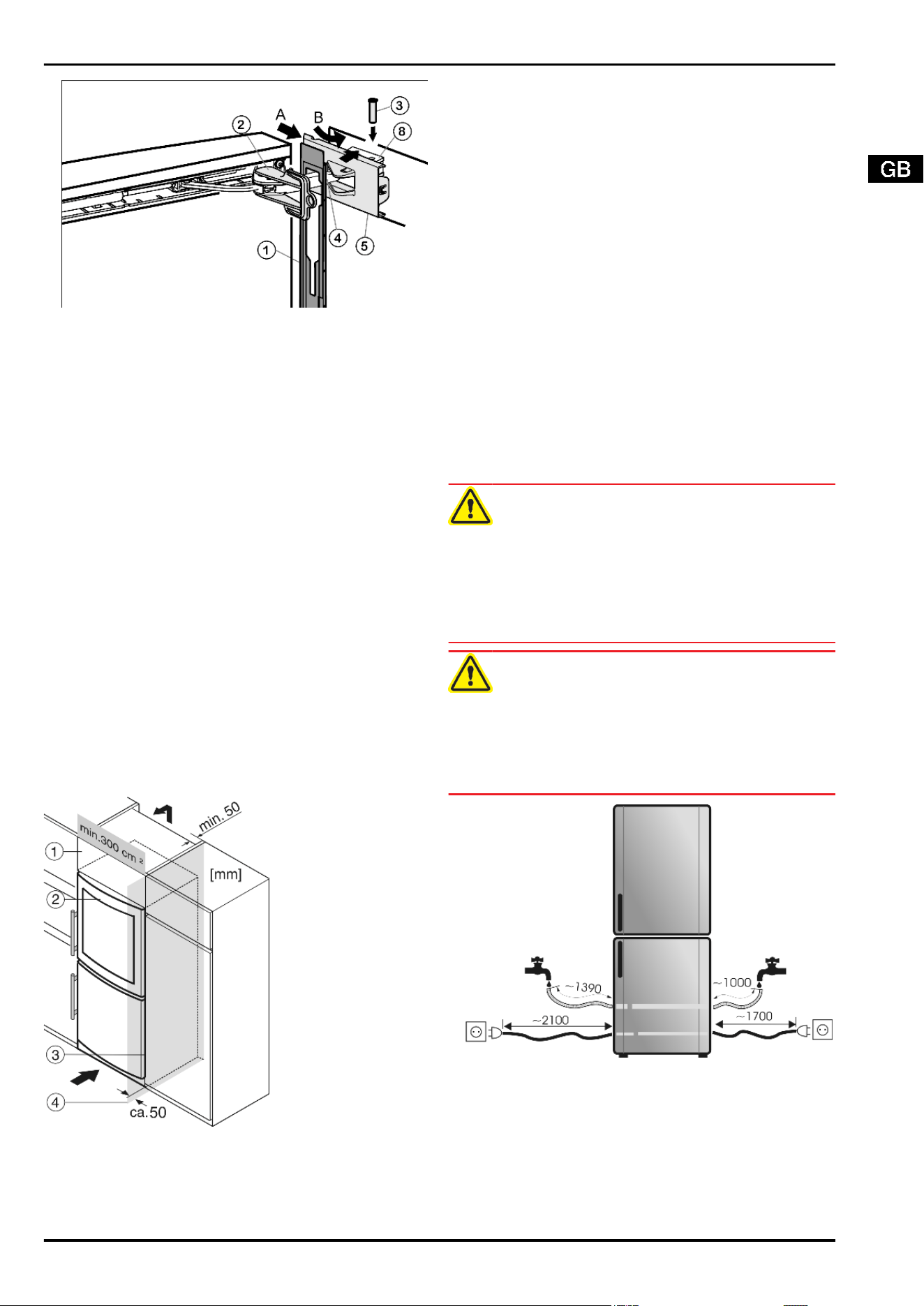
Fig. 16
u
Attach the faceplate
Fig. 16 (1)
to the soft stop bracket
Fig. 16 (4)
so that the catches face inwards and the front faces
the appliance.
u
Slide on the cover
Fig. 16 (5)
from the outside (A) and swivel
it over the bearing part
Fig. 16 (8)
(B).
u
Attach the cover
Fig. 16 (5)
and engage it as far as the first
detent.
w
The openings for the pin are on top of one another after the
soft stop bracket has been positioned.
u
Draw the soft stop bracket
Fig. 16 (4)
towards the bearing part
and insert the pin
Fig. 16 (3)
from above so that the square
sits in the recess.
u
Now completely snap the cover
Fig. 16 (5)
onto the bearing
part
Fig. 16 (8)
.
w
Pay attention that the cover fits properly so that the door closes
properly and the pin is secured.
u
Twist the safety lock
Fig. 16 (2)
for removal.
u
Snap the faceplate
Fig. 16 (1)
onto the door.
u
Turn the cover
Fig. 6 (6)
180°, attach and engage it on the
handle side.
4.1.12 Aligning the doors
u
If necessary, align the doors to the appliance housing by way
of the two oblong holes in the lower turn hinge
Fig. 11 (43)
and
middle turn hinge
Fig. 10 (31)
, then tighten the screws.
u
Engage the cover
Fig. 11 (41)
on the lower turn hinge.
4.2 Insertion into a row of kitchen units
Fig. 17
(1) Stack cabinet (3) Kitchen cabinet
(2) Appliance (4) Wall
The appliance can be inserted into a row of kitchen units. To
match the appliance
Fig. 17 (2)
to the height of the row of units,
a suitable stack cabinet
Fig. 17 (1)
can be fitted above the appli-
ance.
When inserting the appliance into a row of standard kitchen units
(max. depth 580 mm), the appliance can be installed directly next
to the kitchen unit
Fig. 17 (3)
. The appliance door projects relative
to the front of the kitchen unit by 34 mm at the side and by 50 mm
in the middle of the appliance. It can be opened and closed per-
fectly as a result.
Important for the ventilation:
-
At the back of the stack cabinet there has to be a ventilation
duct of at least 50 mm depth throughout the width of the stack
cabinet.
-
The ventilation space under the ceiling has to be at least
300 cm
2
.
-
The larger the ventilation space, the more energy-saving the
appliance is in operation.
If the appliance is installed with the hinges next to a wall
Fig. 17 (4)
, the distance between appliance and wall has to be at
least 50 mm. This corresponds to the projection of the handle
when the door is open.
4.3 Water connection
WARNING
Danger of electric shock!
u
Disconnect the appliance by unplugging it before you connect
it to the water line.
u
Shut off the water supply before you connect the water feed
lines of the IceMaker.
u
The connection to the drinking water system may be carried
out only by a qualified gas fitter and plumber.
WARNING
Risk of poisoning!
u
The water quality has to conform with the drinking water ordi-
nance of the respective country in which the appliance is used.
u
The IceMaker serves exclusively for making ice cubes in
household quantities and has to be operated with water suit-
able for the purpose.
Fig. 18
Putting into operation
7
- The water pressure has to be be-
tween 1.5 bar and 6 bar. (0.15 MPa -
0.6 MPa)
- The water supply to the appliance
must be via a cold water pipe which
withstands the operating pressure
and complies with the hygiene regu-
lations.
Use the accompanying stainless
steel hose for the purpose (1.5 m
long). A 3 m hose is available from the
customer service department and
has to be fitted by an expert.
In the hose connecting piece is a
sieve with seal.
- Between the hose and the domestic
water connection there has to be a
stopcock to interrupt the water supply
in case of need.
- The stopcock should be outside the
area at the back of the appliance and
should be readily accessible so that
the appliance can be slid in as far as
possible and the stopcock can be
closed quickly if necessary. Observe
the clearances.
- All the fixtures and fittings used for
water supply have to comply with the
applicable regulations of the respec-
tive country.
- Do not damage or kink the water inlet
pipe when installing the appliance.
u
Connect the straight part of the accompanying stainless steel
hose to the stopcock.
The solenoid valve is at the bottom back of the appliance. The
connection dimension of the solenoid valve is 3/4”.
u
Connect the angled part of the stainless steel hose to the sol-
enoid valve.
u
Open the stopcock of the water supply and check
that the entire water system is leakproof.
Before initial use:
u
Have the water pipe bled of air by the proper ex-
pert.
4.4 Transporting the appliance
CAUTION
Risk of injury and danger of damage as a result of incorrect trans-
port!
u
Transport the appliance in a packed condition.
u
Transport the appliance upright.
u
Do not transport the appliance without assistance.
WARNING
Risk of injury due to broken glass!
In case of transport at an altitude of over 1500 m the glass panes
of the door may break. The fragments have sharp edges and may
cause serious injury.
u
Take appropriate protective action.
4.5 Installing the appliance
In the event that the appliance is damaged, contact the supplier
immediately before connecting to the mains.
The floor at the site must be flat and level.
Do not install the appliance in a location where it is exposed to
direct radiation of the sun, next to a cooker, heater and similar.
Always install the appliance directly against the wall.
Do not install the appliance without assistance.
Standard EN 378 specifies that the room in which you install your
appliance must have a volume of 1 m
3
per 8 gof R 600a refrigerant
used in the appliance. If the room in which the appliance is in-
stalled is too small, a flammable gas-air mixture may form in the
event of a leakage in the refrigeration circuit. The quantity of re-
frigerant used in your appliance is indicated on the type plate on
the inside of the appliance.
WARNING
Fire hazard due to dampness!
If live parts or the mains lead become damp this may cause short
circuits.
u
The appliance is designed for use in enclosed areas. Do not
operate the appliance outdoors or in areas where it is exposed
to splash water or damp conditions.
WARNING
Fire hazard due to refrigerant!
The refrigerant R 600a is environmentally friendly but flammable.
Escaping refrigerant may ignite.
u
Do not damage the piping of the refrigeration circuit.
WARNING
Fire hazard and danger of damage!
u
Do not place appliances emitting heat e.g. microwaves, toast-
ers etc. on the appliance!
WARNING
Fire hazard and risk of damage due to blocked ventilation grille!
u
Always keep the ventilation grille free. Always ensure that the
appliance is properly ventilated.
u
Detach the connecting cable from the rear of the appliance,
removing the cable holder at the same time because other-
wise there will be vibratory noise!
u
Remove the protective film from the outside of the appliance.
u
Evenly apply an agent for care of stainless steel, wiping in the
direction of the grain.
w
Subsequent cleaning becomes easier as a result.
u
Remove the protective film from the decorative trims and
drawer fronts.
u
Remove all transit supports.
u
Dispose of packaging material. See section on packaging dis-
posal.
ATTENTION*
Risk of damage due to condensate!
If your appliance is not a Side-by-Side (SBS) appliance:
u
do not install the appliance directly alongside a further refrig-
erator/freezer.
u
Align the appliance so that it
stands firmly and on a level by ap-
plying the accompanying spanner
to the adjustable-height feet (A)
and using a spirit level.*
u
Then support the door: Extend the
adjustable foot at the turn hinge
(B) until it rests on the floor and
then make a further 90° turn.*
*
Putting into operation
8
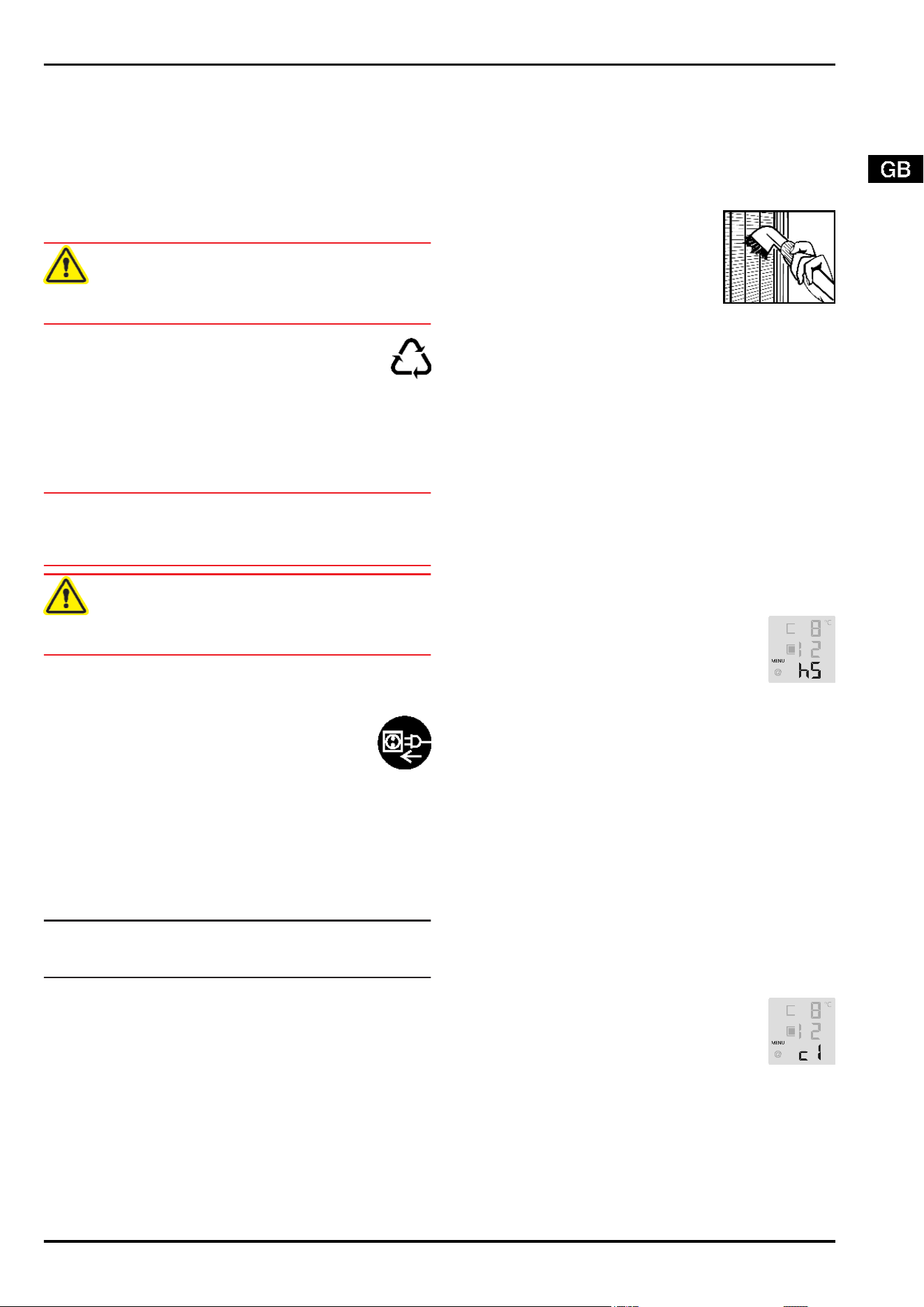
If your appliance is a Side-by-Side appliance (SBS):
u
Proceed according to the Side-by-Side combined fridge-
freezer installation instructions. (Accessories bag of the SBS
freezer/appliance with freezer compartment)*
If the appliance is installed in a very damp environment, conden-
sate may form on the outside of the appliance.
u
Always see to good ventilation at the installation site.
4.6 Disposing of packaging
WARNING
Danger of suffocation due to packing material and plastic film!
u
Do not allow children to play with packing material.
The packaging is made of recyclable materials:
-
corrugated board/cardboard
-
EPS moulded parts
-
polythene bags and sheets
-
polypropylene straps
u
Take the packaging material to an official collecting point.
4.7 Connecting the appliance
ATTENTION
Risk of damage to the electronic control system!
u
Do not use stand-alone inverters (conversion of d.c. to a.c./
three-phase) or energy saving plugs.
WARNING
Fire and overheating hazard!
u
Do not use extension cables or multiple socket outlets.
The type of current (alternating current) and voltage at the instal-
lation site have to conform with the data on the type plate (see
section on description of appliance and equipment).
Connect the appliance only with a properly installed
socket outlet with earthing contact. The socket outlet
must be fused with 10 A or higher.
It must be easily accessible so that the appliance can
be quickly disconnected from the supply in an emer-
gency.
u
Check the electrical connection.
u
Clean the appliance. More information on this is in the section
on cleaning.
u
Plug in the power plug.
4.8 Switching on the appliance
Note
u
To switch on the entire appliance it is necessary only to switch
on the freezer compartment.
Put the appliance into operation about 2 hours before first loading
food to be frozen.
Do not load food to be frozen before the temperature display
reads -18 °C.
4.8.1 Switching on the freezer compartment
u
Press On/Off button, freezer compartment
Fig. 3 (3)
.
w
The wine zone temperature display and the alarm button flash
until the set temperature is reached.
w
The freezer compartment temperature display and the alarm
button flash until the temperature is sufficiently cold. If the
temperature is above 0 °C, dashes flash. If it is below, the
current temperature flashes.
5 Control
5.1 Saving energy
u
Always pay attention to good ventilation.
u
Keep the time the appliance is open to a minimum.
u
Store food logically.
Accumulated dust increases the energy con-
sumption:
u
Once a year, dust the refrigerating unit to-
gether with the metal grille of the heat ex-
changer at the back of the appliance.
5.2 Brightness of the temperature dis-
play
You can adjust the brightness of the temperature display to the
light conditions of the room in which the appliance is installed.
5.2.1 Adjusting the brightness
The brightness is adjustable between h0 (no illumination) and h5
(maximum luminosity).
u
To activate the setting mode: press the SuperFrost button
Fig. 3 (2)
for about 5 s.
w
The display indicates c.
w
The menu symbol
Fig. 3 (20)
shines.
u
Using the Up setting button, freezer compartment
Fig. 3 (5)
or
Down setting button, freezer compartment
Fig. 3 (4)
select
h.
u
To confirm: briefly press the SuperFrost button
Fig. 3 (2)
.
u
To make the display brighter: press Up button,
freezer compartment
Fig. 3 (5)
.
u
To make the display darker: press Down button,
freezer compartment
Fig. 3 (4)
.
u
To confirm: press SuperFrost button
Fig. 3 (2)
.
w
The brightness is adjusted to the new value.
u
To deactivate the set-up mode: press On/Off button, freezer
compartment
Fig. 3 (3)
.
-or-
u
Wait for 5 minutes.
w
The temperature is indicated again in the temperature display.
5.3 Child proofing
The child-proofing function enables you to make sure that the
appliance is not inadvertently switched off by playing children.
5.3.1 Setting the child lock
u
To activate the setting mode: press SuperFrost button
Fig. 3 (2)
for about 5 s.
w
The display indicates c.
w
The menu symbol
Fig. 3 (20)
shines.
u
Briefly press the SuperFrost button
Fig. 3 (2)
to confirm.
u
To switch on: Using the Up setting button, freezer
compartment
Fig. 3 (5)
or Down setting button,
freezer compartment,
Fig. 3 (4)
select c1.
u
To switch off: Using the Up setting button, freezer
compartment
Fig. 3 (5)
or Down setting button,
freezer compartment,
Fig. 3 (4)
select c0.
u
To confirm: press SuperFrost button
Fig. 3 (2)
.
w
When the child lock symbol
Fig. 3 (19)
shines, the child lock
is activated.
u
To deactivate the set-up mode: press On/Off button, freezer
compartment
Fig. 3 (3)
.
-or-
u
Wait for 5 minutes.
w
The temperature is indicated again in the temperature display.
Control
9
5.4 Door alarm
For refrigerator and freezer compartment
If the door is open longer then 60 s, the audible alarm sounds.
The audible alarm is automatically silenced when the door is
closed.
5.4.1 Muting the door alarm
The audible alarm can be muted when the door is open. The
sound switch-off function is active as long as the door is left open.
u
Press alarm button
Fig. 3 (1)
.
w
The door alarm is silenced.
w
The temperature is indicated in the display. The display
changes to the normal temperature display.
5.5 Temperature alarm
The audible alarm sounds if the freezer temperature is not cold
enough.
The temperature display and the alarm symbol
Fig. 3 (6)
flash at
the same time.
The cause of the temperature being too high may be:
-
too much warm ambient air flowed in when rearranging and
removing food
-
power failure for some time
-
the appliance is faulty
The audible alarm is automatically silenced, the alarm symbol
Fig. 3 (6)
goes out and the temperature display stops flashing
when the temperature is sufficiently cold/warm again.
If the alarm status persists, proceed as indicated in the section
on troubleshooting.
Note
Food may be spoilt if the temperature is not cold enough.
u
Check the quality of the food. Do not consume spoiled food.
5.5.1 Muting the temperature alarm
The audible alarm can be muted. When the temperature is suf-
ficiently cold again, the alarm function is active again.
u
Press alarm button
Fig. 3 (1)
.
w
The audible alarm is silenced.
5.6 Freezer compartment
You can store frozen food, make ice cubes and freeze fresh food
in the freezer compartment.
5.6.1 Freezing food
The maximum load for an individual drawer and the plate is 25 kg
frozen food.
CAUTION
Risk of injury due to broken glass!
Bottles and cans containing drinks may burst when being frozen.
This applies particularly to sparkling drinks.
u
Do not freeze bottles and cans containing drinks!
In order that the food is rapidly frozen through to the core, do not
exceed the following quantities per pack:
- Fruit, vegetables up to 1 kg
- Meat up to 2.5 kg
u
Pack the food in portions in freezer bags, reusable plastic,
metal or aluminium containers.
5.6.2 Thawing food
- at room temperature
- in a microwave oven
- in a conventional or fan oven
u
Food once thawed should be re-frozen only in exceptional
cases.
5.6.3 Setting the temperature in the freezer com-
partment
The appliance is pre-set for normal operation.
The temperature can be set between -16 °C and -26 °C, the rec-
ommended temperature is -18 °C.
u
To set the temperature higher: press Up button, freezer com-
partment
Fig. 3 (5)
.
u
To set the temperature lower: press Down button, freezer
compartment
Fig. 3 (4)
.
w
When the button is pressed the first time, the previous value
is indicated in the temperature display of the freezer compart-
ment.
u
To change the temperature in 1 °C steps: briefly press the
button.
-or-
u
To change the temperature continuously: hold down the but-
ton.
w
The value is displayed flashing during the setting operation.
w
The actual temperature is displayed about 5 s after the last
press of a button. The temperature slowly adjusts to the new
value.
5.6.4 SuperFrost
With this function you can freeze fresh food quickly through to
the core. The appliance operates with maximum refrigeration.
The noise of the refrigeration unit may be temporarily louder as
a result.
The maximum amount of fresh food which can be frozen in 24 h
is indicated on the type plate under "freezing capacity ... kg/
24h". This amount varies according to the model and climate rat-
ing.
Freezing with SuperFrost
You do not have to activate SuperFrost in the following cases:
- when placing frozen food in the freezer
- when freezing up to about 2 kg fresh food a day
u
Briefly press the SuperFrost button
Fig. 3 (2)
once.
w
The SuperFrost symbol
Fig. 3 (24)
shines.
w
The freezer temperature drops, the appliance operates with
maximum refrigerating performance.
For a small amount of food:
u
wait about 6 h.
u
Place the fresh food in the top drawers.
For the maximum amount of food:
u
wait about 24 h.
u
Place wrapped food straight on the shelves and, once frozen,
put it into the drawers.
w
SuperFrost is automatically deactivated. Depending on the
quantity placed inside, after 30 h at the earliest, 65 h at the
latest.
w
Freezing is concluded.
w
The SuperFrost symbol
Fig. 3 (24)
goes out.
w
The appliance continues to operate in the energy-saving, nor-
mal mode.
5.6.5 Drawers
Note
The energy consumption increases and the cooling performance
decreases if there is insufficient ventilation.
For appliances with NoFrost:
u
Leave the bottom drawer in the appliance!
u
Always keep the air slits of the fan free at the rear wall!
Control
10
u
To store frozen food directly on the shelves: pull the drawer
forwards and lift it out.
5.6.6 Shelves
u
To remove the shelf: lift up at the front and
pull out.
u
To put the shelf back: simply push in as far
as it will go.
5.6.7 VarioSpace
Apart from being able to remove
the drawers, you can also remove
the shelves, creating space for
large items of frozen food. Poul-
try, meat, large pieces of game
and high bakery products can be
frozen in one piece and prepared.
u
The maximum load of frozen
food for an individual drawer or
shelf is 25 kg.
5.6.8 Cold storage accumulators
5.6.9 Freezer tray
The freezer tray allows you to freeze berries, herbs, vegetables
and other small items of food without them sticking together.
Items being frozen will largely retain their shape, and it will be
easier to remove exactly the right quantity later on.
Using the freezer tray
u
Spread the items out loosely on
the freezer tray.
u
Attach the freezer tray in one of the
upper drawers.
u
Allow the food to freeze through
for 10 to 12 h.
u
Transfer the frozen food to freezer
bags or containers.
u
Store freezer bags or containers in a drawer.
u
To thaw the items, spead them out loosely again.
5.6.10 Using cold storage accumulators
u
Place the cold storage accumula-
tors in the freezer tray to save
space.
u
Place the frozen cold storage ac-
cumulators straight on top of the
frozen food in the top large draw-
er.
w
This way the frozen food will keep
cool longest in case of power fail-
ure.
5.6.11 IceMaker
The IceMaker is in the top drawer of the freezer compartment.
The drawer is marked "IceMaker".
Make certain that the following conditions are met:
-
The appliance is level.
-
The appliance is connected.
-
The freezer compartment is switched on.
-
The IceMaker is connected to the water supply.
Switching on the IceMaker
Fig. 19
u
Pull out the drawer.
u
Press the On/Off button
Fig. 19 (1)
so that the LED
Fig. 19 (2)
shines.
u
Push in the drawer.
Note
u
The IceMaker produces ice cubes only if the drawer is fully
closed.
Switching off the IceMaker
If no ice cubes are needed, the IceMaker can be switched off
independently of the freezer compartment.
When the IceMaker is put out of service, clean it. This ensures
that no water or ice remains in the IceMaker.
When the IceMaker is switched off, the IceMaker drawer can also
be used for freezing and storing food.
u
Press the On/Off button for about 1 second until the LED goes
out.
Producing ice cubes
The production capacity depends on the freezer temperature.
The lower the temperature, the more ice cubes can be produced
in a specific period.
The ice cubes drop out of the IceMaker into the drawer. When a
certain filling level is reached, no more ice cubes are produced.
If large quantities of ice cubes are needed, the complete Ice-
Maker drawer can be exchanged for the adjacent drawer. When
the drawer is closed, the IceMaker automatically re-commences
production.
Once the IceMaker has been switched on for the first time, it may
take up to 24 hours until the first ice cubes are produced.
Note
u
Do not consume or use the first three loads of ice cubes. This
applies if the appliance is used for the first time and if it has
been out of use for a long time. This ensures that the water
line is thoroughly rinsed.
Setting the water intake time
The opening time of the IceMaker valve can be set. The water
intake time is adjustable in steps from E1 (short intake time) to E8
(long intake time).
u
To activate the setting mode: press the SuperFrost button
Fig. 3 (2)
for about 5 s.
w
The display indicates c.
w
The menu symbol
Fig. 3 (20)
shines.
u
Using the Up setting button, freezer compartment
Fig. 3 (5)
and Down setting button, freezer compartment
Fig. 3 (4)
se-
lect E.
u
To confirm: briefly press the SuperFrost button
Fig. 3 (2)
.
Control
11
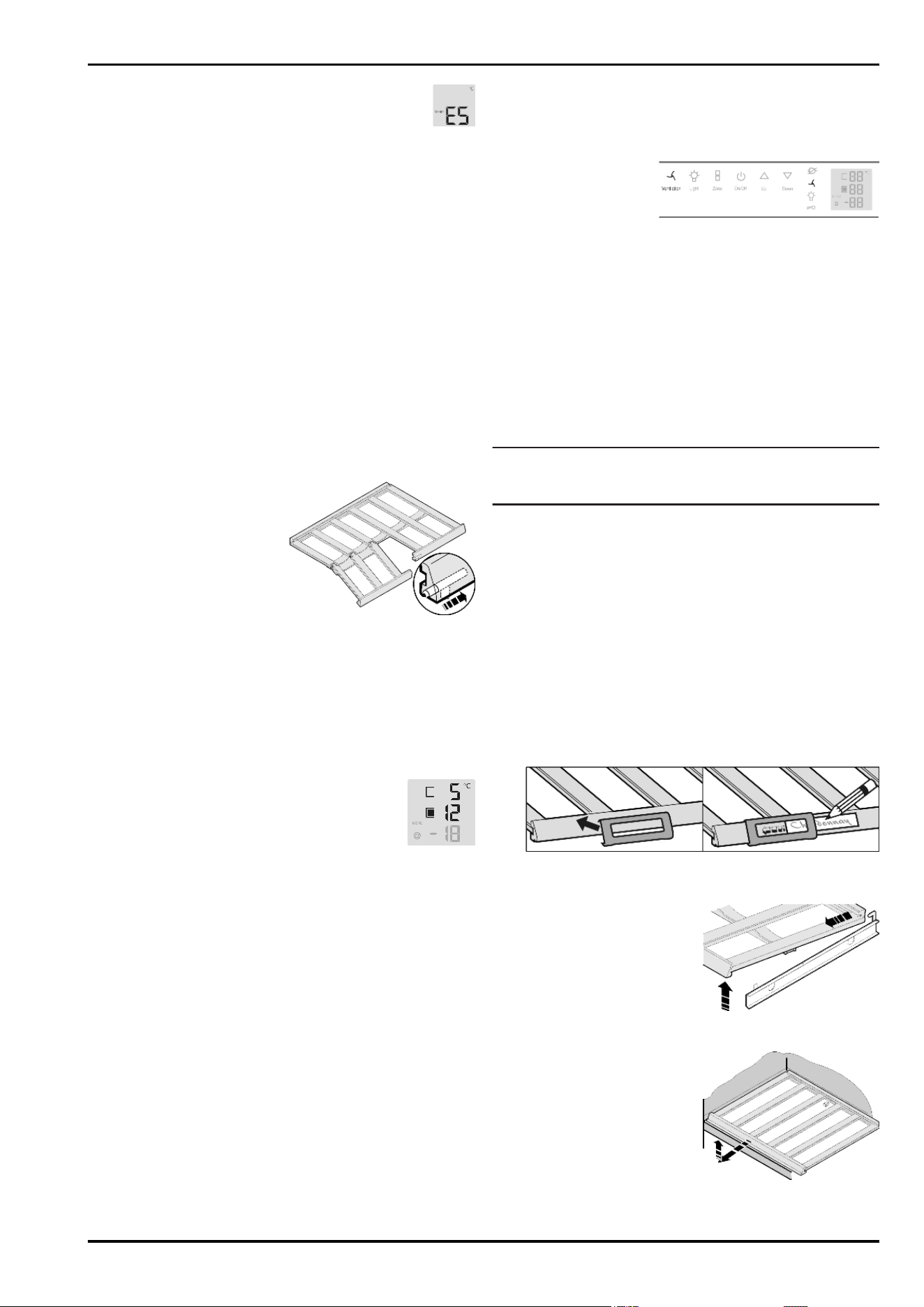
u
To increase the water intake time: press the Up set-
ting button, freezer compartment
Fig. 3 (5)
.
u
To reduce the water intake time: press the Down set-
ting button, freezer compartment
Fig. 3 (4)
.
u
To confirm: press the SuperFrost button
Fig. 3 (2)
.
u
To deactivate the setting mode: press the On/Off button,
freezer compartment
Fig. 3 (3)
.
-or-
u
Wait for 2 minutes.
w
The temperature is indicated again in the temperature display.
5.7 Wine zone
You can bring your wines to the ideal drinking temperature slowly
and gradually in the wine zone.
5.7.1 Storing wine bottles
41 Bordeaux bottles(0.75 l) can be stored in the wine zone.
u
Store white wine only in one compartment and red wine only
in the other, since both compartments can be set to inde-
pendent temperatures.
u
If possible, lay bottles of the same type of wine side by side
on the same grid shelf.
u
Rearrange bottles as seldom as possible.
u
Stored open bottles on the
folded down wooden grid
shelf.
u
To fold down the wooden grid
shelf: press the lock under
the trim sideways.
w
The wooden grid shelf folds
down.
5.7.2 Setting the temperature in the wine zone
The appliance is pre-set for normal operation. The temperature
can be set from 20 °C to 5 °C, the recommended temperatures
are 8 °C to 12 °C.
The wine zone is divided into two wine compartments, which can
be set to different temperatures, as needed.
u
To select the wine compartment: press the zone button
Fig. 3 (15)
.
w
The selected wine compartment is indicated in
the temperature display.
u
To set the temperature warmer: press the Up setting button,
wine zone
Fig. 3 (13)
.
u
To set the temperature colder: press the Down setting button,
wine zone
Fig. 3 (12)
.
w
The first time the button is pressed, the previous value is in-
dicated in the temperature display, upper wine zone
Fig. 3 (8)
or in the temperature display, lower wine zone
Fig. 3 (7)
.
u
To change the temperature in 1 °C steps: briefly press the
button.
-or-
u
To change the temperature continuously: hold down the but-
ton.
w
During setting the new value is displayed flashing.
w
The actual temperature is displayed about 5 s after the last
press of a button. The temperature slowly adjusts to the new
value.
5.7.3 Fan
When the fan runs, the relative humidity in the interior increases
so that the cork does not dry out.
When the fan is activated, the energy consumption increases. To
save energy, the fan switches off automatically when the door is
open.
Switching on the fan
u
Briefly press the fan
button
Fig. 3 (17)
.
w
The fan symbol shines.
Switch off the fan
u
Briefly press the fan button
Fig. 3 (17)
.
w
The fan symbol is dark.
w
The fan runs only when the compressor runs. The humidity is
low.
5.7.4 Dim mode
For glazed door models you can set the dim mode of the light,
i.e. the intensity with which the light is to shine after the door has
closed.
Setting the dim mode
Note
u
When the dim mode is deactivated, the light becomes slowly
darker after the door has closed and then goes out.
u
Briefly press the Light button
Fig. 3 (16)
.
w
The Light button
Fig. 3 (16)
shines. The dim mode is activated.
The settings apply to all wine compartments.
u
For a brighter light adjustment: press Light button
Fig. 3 (16)
and Up setting button, wine zone
Fig. 3 (13)
at the same time.
u
For a darker light adjustment: press Light button
Fig. 3 (16)
and Down setting button, wine zone
Fig. 3 (12)
at the same
time.
5.7.5 Labels
You can note down on the labels the type of wine stored in the
respective compartment. Additional labels can be obtained from
your specialist dealer.
Labelling
5.7.6 Wooden shelf
Pay attention that the wooden
shelf does not get caught on the
rear hook.
u
To remove the folding wooden
shelf: lift it off the pull-out rail
and draw it forwards.
u
To insert the wooden folding shelf: slide it under the rear hook
and press onto the rails so that they audibly snap into place.
u
To remove lower wooden
shelf: pull it forwards at an an-
gle and simultaneously raise it.
u
To insert lower wooden shelf:
slide it in over the stop on the
intervening shelves up to the
rear wall of the appliance and
press it down.
Control
12
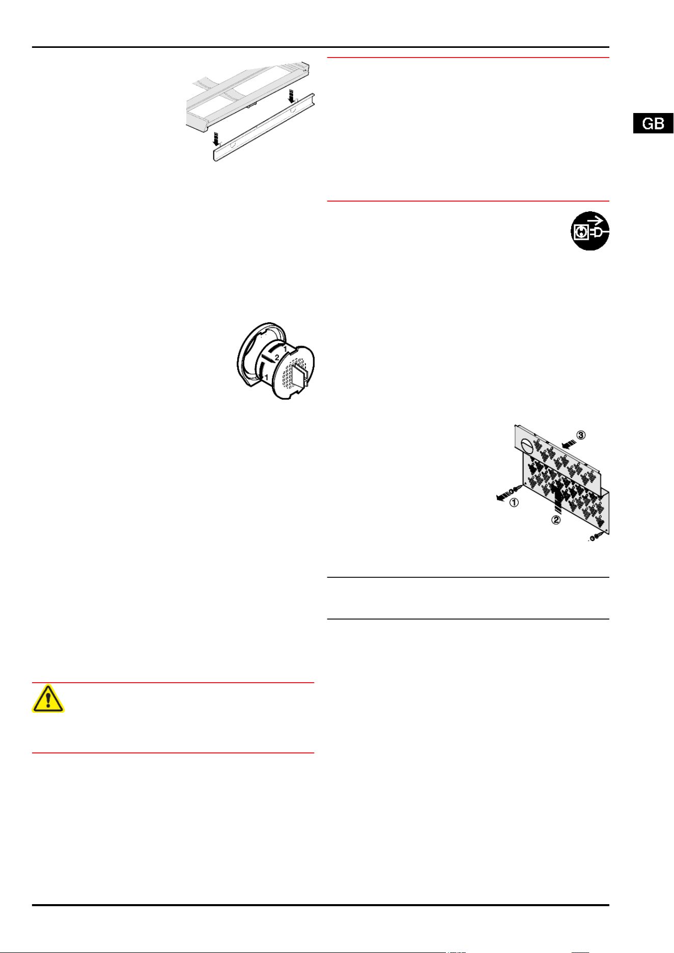
u
To insert other wooden
shelves: place on the rails.
6 Maintenance
6.1 Replacing the activated charcoal fil-
ter
The activated charcoal filter ensures ideal air quality and should
therefore be replaced annually. It can be ordered from a speci-
alised dealer.
Each wine zone is equipped with an activated charcoal filter of
its own.
u
Take the activated charcoal filter by the
grip.
u
Turn the activated charcoal filter
through 90° to the right or left
Fig. 20 (1)
.
u
Remove
Fig. 20 (2)
the activated char-
coal filter.
u
Insert the new activated charcoal filter
with the grip in an upright position.
u
Turn the new activated charcoal filter
through 90° to the right or left
Fig. 20 (1)
until it snaps into place.
Fig. 20
6.2 Defrosting with NoFrost
The NoFrost system automatically defrosts the appliance.
Wine zone:
The defrost water evaporates due to the compressor heat. Drops
of water on the rear wall are perfectly normal.
u
Regularly clean the drain opening to allow the water to flow
away. (see section on cleaning the appliance)
u
Clean the rubber lip. (see section oncleaning the appliance)
Freezer compartment:
The moisture condenses on the evaporator, is periodically de-
frosted and evaporates.
u
The appliance does not have to be manually defrosted.
6.3 Cleaning the appliance.
Before cleaning:
CAUTION
Risk of injury and damage as a result of hot steam!
Hot steam may damage the surfaces and cause burns.
u
Do not use any steam cleaners!
ATTENTION
Incorrect cleaning damages the appliance!
u
Do not use cleaning agents in concentrated form.
u
Do not use any scouring or abrasive sponges or steel wool.
u
Do not use any cleaning agents containing sand, chloride,
chemicals or acid.
u
Do not use chemical solvents.
u
Do not damage or remove the type plate on the inside of the
appliance. It is important for the customer service.
u
Do not pull off, bend or damage cables or other components.
u
Do not allow any cleaning water to enter the drain channel,
ventilation grille or electrical parts.
u
Empty the appliance.
u
Pull out the power plug.
- Use soft cleaning cloths and a multi-purpose clean-
ing agent with neutral pH value.
- Only use food compatible cleaning and care agents
on the inside of the appliance.
Outside surfaces and interior:
u
Clean the glass door with a standard glass cleaning agent and
a soft cloth.
u
Clean the plastic surfaces, outside and inside, by hand using
lukewarm water and a little washing-up liquid.
Clean stainless steel surfaces with a standard stainless steel
cleaning agent. Darker areas at the beginning and quite an in-
tensive colour of the stainless steel surface are normal.
u
Do not apply cleaners to glass or plastic surfaces so as not to
scratch them.
u
To clean stainless steel surfaces: evenly apply an agent for
care of stainless steel, wiping in the direction of the grain.
To clean the drain opening:
u
remove the wooden grid shelves
and detach the pull-out rails.
u
Remove the caps and screws of
the sheet covering and set them
aside (1).
u
Lift the sheet covering (2) and pull
it forwards (3).
u
To clean the drain opening: re-
move any deposits with a fine in-
strument, e.g. a cotton bud.
Items of equipment:
u
Wipe wooden grid shelves with a dry, lint-free cloth.
Note
u
Do not clean wooden grid shelves with water and washing-up
liquid.
u
Clean other items of equipment by hand with lukewarm water
and a little washing-up liquid.
After cleaning:
u
Wipe dry the appliance and items of equipment.
u
Connect the appliance and switch it on again.
u
Activate SuperFrost . (see section on SuperFrost)
When the temperature is sufficiently cold:
u
Put the food back inside.
6.4 Cleaning the IceMaker
The drawer of the IceMaker has to be emptied and slid in.
u
To activate the setting mode: press the SuperFrost button
Fig. 3 (2)
for about 5 s.
w
The display indicates c.
w
The menu symbol
Fig. 3 (20)
shines.
u
Using the Up setting button, freezer compartment
Fig. 3 (5)
or
Down setting button, freezer compartment
Fig. 3 (4)
select
Ic.
u
To confirm: briefly press the SuperFrost button
Fig. 3 (2)
.
Maintenance
13
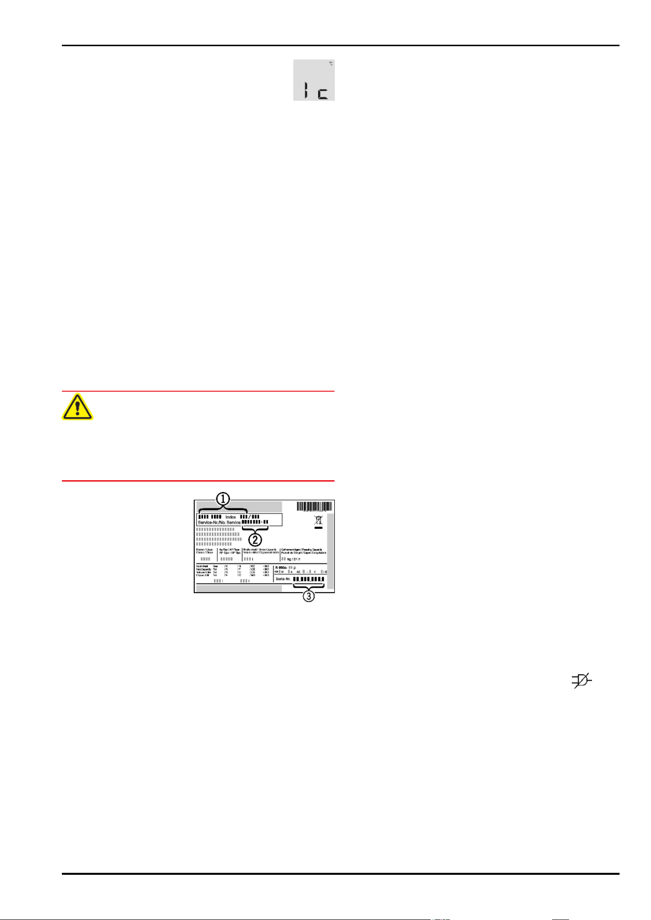
u
Using the Up setting button, freezer compartment
Fig. 3 (5)
/ Down setting button, freezer compart-
ment
Fig. 3 (4)
select Ic.
u
To confirm: press the SuperFrost button
Fig. 3 (2)
.
w
The IceMaker moves into the cleaning position and switches
off.
u
To deactivate the setting mode: press the On/Off button,
freezer compartment
Fig. 3 (3)
.
-or-
u
Wait for 2 minutes.
w
The temperature is indicated again in the temperature display.
u
Remove the drawer.
u
Clean the ice cube tray and drawer with warm water. If nec-
essary, use mild washing-up liquid. Then rinse.
u
Slide in the drawer again.
If washing-up liquid was used:
u
throw away the first three loads of ice cubes to get rid of any
remaining washing-up liquid.
Either leave the IceMaker switched off in this position or switch
the IceMaker on again (see the section on switching the IceMaker
on).
6.5 Customer service
First check whether you can correct the fault yourself by refer-
ence to the list in the section on troubleshooting. If this is not the
case, please contact the customer service whose address is giv-
en in the enclosed customer service list.
WARNING
Risk of injury if repair work is not carried out professionally!
u
Have any repairs to and intervention in the appliance and
mains power cable, which are not expressly mentioned in the
section on maintenance, carried out by the customer service
only.
u
Read the appliance
designation
Fig. 21 (1)
,
service No.
Fig. 21 (2)
and serial No.
Fig. 21 (3)
off the type
plate located inside the
appliance on the left-
hand side.
Fig. 21
u
Notify the customer service, specifying the fault, appliance
designation
Fig. 21 (1)
, service No.
Fig. 21 (2)
and serial No.
Fig. 21 (3)
.
w
This will help us to provide you with a faster and more accurate
service.
u
Keep the appliance closed until the customer service arrives.
w
The food will stay cool longer.
u
Pull out the mains plug (not by pulling the connecting cable)
or switch off the fuse.
7 Malfunction
Your appliance is designed and manufactured for a long life span
and reliable operation. If a malfunction nonetheless occurs dur-
ing operation, check whether it is due to a handling error. In this
case you will have to be charged for the costs incurred, even
during the warranty period. You may be able to rectify the follow-
ing faults yourself:
Appliance does not work.
→
The appliance is not switched on.
u
Switch on the appliance.
→
The power plug is not properly inserted in the wall socket.
u
Check power plug.
→
The fuse of the wall socket is not in order.
u
Check fuse.
A bubbling and gurgling noise
→
This noise comes from the refrigerant flowing in the refriger-
ation circuit.
u
The sound is normal.
A quiet clicking noise
→
The noise is produced whenever the refrigeration unit (motor)
automatically switches on or off.
u
The sound is normal.
A hum. It is briefly a little louder when the refrigeration unit
(the motor) switches on.
→
The refrigeration increases automatically when the Super-
Frost, function is activated, fresh food has just been placed
in the appliance or the door has been left open for a while.
u
The sound is normal.
→
The refrigeration increases automatically when the Super-
Cool function is activated, fresh food has just been placed in
the appliance or the door has been left open for a while.
u
The sound is normal.
→
The ambient temperature is too high.
u
See section on range of appliance use
A low hum
→
The sound is produced by air flow noise of the fan.
u
The sound is normal.
Vibratory noise
→
The appliance is not standing firmly on the floor. As a result,
adjoining units or objects are set into vibration by the running
refrigeration unit.
u
Move the appliance away a little and align it using the adjust-
able feet.
u
Move bottles and containers apart.
Flow sound at the soft stop mechanism.
→
The noise is produced when the door is opened and closed.
u
The sound is normal.
Mould on the wine bottles
→
Similarly as with other forms of storage, a little mould may
form depending on the type of adhesive used for the label.
u
Remove residual adhesive.
The temperature display indicates: F0 to F9
→
There is a fault.
u
Contact the customer service. See the section on mainte-
nance.
The temperature display reads:FE
→
There is a fault.
u
Contact the customer service. See the section on mainte-
nance.
The temperature display indicates power failure
. The
warmest temperature reached during the power failure ap-
pears in the temperature display.
→
The freezer temperature rose too high over the last hours or
days due to a power failure or power interruption. When the
power interruption is over, the appliance will continue to op-
erate in the last temperature setting.
u
To cancel the display of the warmest temperature: press alarm
button
Fig. 3 (1)
.
u
Check the quality of the food. Do not consume spoiled food.
Do not re-freeze thawed food.
DEMO shines in the temperature display.
→
The demo mode is activated.
u
Contact the customer service. See the section on mainte-
nance.
Malfunction
14
The outside surfaces of the appliance are warm.
→
The heat of the refrigeration circuit is used to prevent con-
densate from forming.
u
This is normal.
The IceMaker cannot be switched on.
→
The appliance and therefore the IceMaker are not connected.
u
Connect the appliance. See also the section on connection.
The IceMaker does not make any ice cubes.
→
The IceMaker is not switched on.
u
Switch on the IceMaker.
→
The drawer of the IceMaker is not properly closed.
u
Close the drawer properly.
→
The water connection is not open.
u
Open the water connection.
The temperature is not cold enough.
→
The door of the appliance is not properly closed.
u
Close the door of the appliance.
→
Insufficient ventilation.
u
Clear ventilation grilles.
→
The ambient temperature is too high.
u
See section on operating conditions of the appliance.
→
The appliance was opened too frequently or for too long.
u
Wait until the appliance reaches the required temperature it-
self. If not, contact the customer service. See the section on
maintenance.
→
Too much fresh food was placed inside without SuperFrost.
u
See section on SuperFrost.
→
The temperature is incorrectly set.
u
Set to a colder temperature and check after 24 h.
→
The appliance is too close to a heat source.
u
See the section on installation.
The interior light is not on.
→
The appliance is not switched on.
u
Switch on the appliance.
→
The door was open longer than 15 min.
u
The interior light automatically switches off if the door has
been open for about 15 min.
→
The LED interior lighting is faulty or the cover is damaged:
WARNING
Risk of injury due to electric shock!
Live parts are located under the cover.
u
Have the LED interior light changed or repaired only by the
customer service or by specialized personnel trained for the
purpose.
WARNING
Danger of injury due to laser radiation, class 1M.
u
Do not look inside when the cover is open.
8 Decommissioning
8.1 Switching off the appliance
Note
u
To switch off the entire appliance it is necessary only to switch
off the freezer compartment.
8.1.1 Switching off the freezer compartment
u
Press On/Off button, freezer compartment
Fig. 3 (3)
for about
2 s.
w
The temperature displays are dark. The appliance is switched
off.
8.1.2 Switching off the wine zone
u
Press On/Off button, wine zone
Fig. 3 (14)
for about 2 s.
w
the temperature display of the upper wine zone
Fig. 3 (8)
/
temperature display of the lower wine zone
Fig. 3 (7)
is dark.
The wine zone is switched off.
8.2 Taking the appliance out of service
u
Empty the appliance.
u
Pull out the power plug.
u
Clean the appliance (see section on cleaning).
u
Leave the door open to prevent odour.
9 Disposing of the appliance
The appliance contains some reusable materials
and should be disposed of properly - not simply with
unsorted household refuse. Appliances which are no
longer needed must be disposed of in a professional
and appropriate way, in accordance with the current
local regulations and laws.
When disposing of the appliance, ensure that the refrigeration
circuit is not damaged to prevent uncontrolled escape of the re-
frigerant it contains (data on type plate) and oil.
u
Disable the appliance.
u
Pull out the plug.
u
Cut through the connecting cable.
Decommissioning
15

Disposing of the appliance
16