Safety • Assembly • Operation • Tips & Techniques • Maintenance • Troubleshooting • Parts Lists • Warranty
Warning: This unit is equipped with an internal combustion engine and should not be used on or near any uniiproved forest-covered, brush-
covered or grass-covered land unless the engine’s exhaust system is equipped with a spark arrester meeting applicable local or state laws (if any).
If a spark arrester is used, it should be maintained in effective working order by the operator. In the State of California the above is required by law
(Section 4442 of the California Public Resources Code). Other states may have similar laws. Federal laws apply on federal lands. A spark arrester
for the muffler is available through your nearest engine authorized service dealer or contact the service department, P.O. Box 361131 Cleveland,
Ohio 44136-0019.
PRINTED IN U.S.A
READ SAFETY RULES AND INSTRUCTIONS CAREFULLY BEFORE OPERATION
IMPORTANT
OPERATOR’S MANUAL
6/28/06
FORM NO. 769-00381C
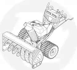
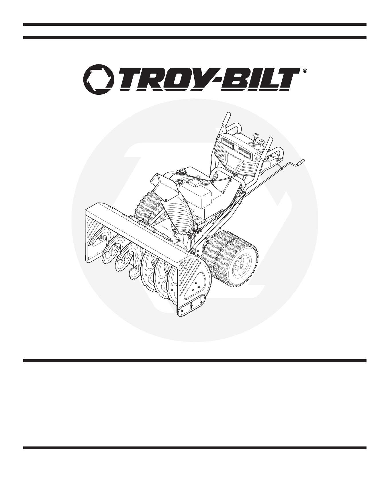
Two-Stage Snow Thrower – Storm 13045
31AH9Q77766
2
Finding and Recording Model Number
Table of Contents
This Operator’s Manual is an important part of your new snow thrower. It will help you assemble,
prepare and maintain the unit for best performance. Please read and understand what it says.
Customer Support .............................................. 2
Safety Labels ...................................................... 3
Safe Operation Practices ................................... 4
Setting Up Your Snow Thrower .......................... 6
Operating Your Snow Thrower ......................... 10
Making Adjustments ........................................ 14
Maintaining Your Snow Thrower ...................... 16
Off-Season Storage .......................................... 22
Troubleshooting ................................................ 23
Illustrated Parts List ......................................... 24
Warranty ............................................................ 31
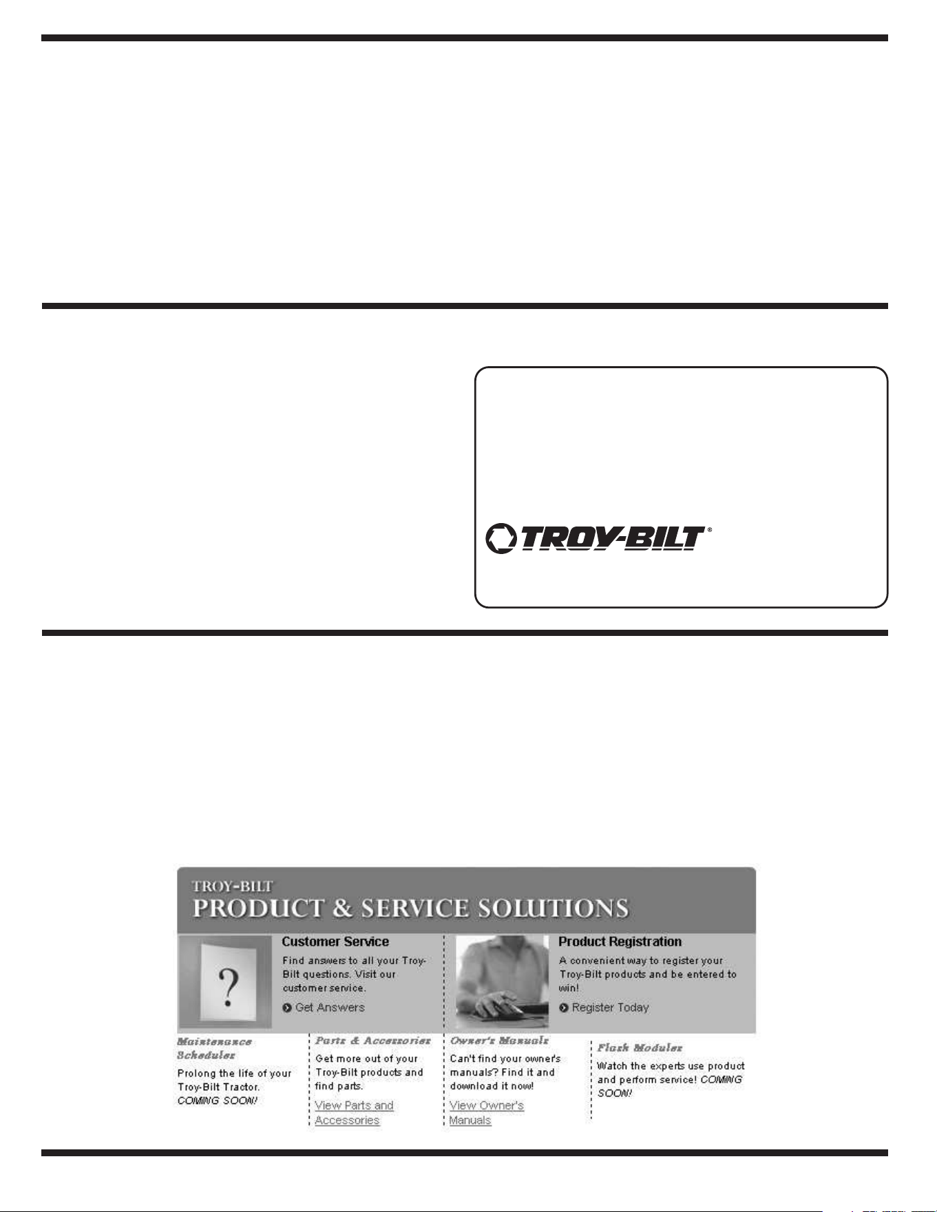
Customer Support
Specifications are subject to change without notification or obligation. Images may not reflect your exact model and are for reference purposes only.
www.troybilt.com
TROY-BILT LLC
P. O. BOX
361131
CLEVELAND, OH 44136
866-840-6483
330-558-7220
If you have difficulty assembling this product or have any questions regarding the controls, operation, or maintenance of this
unit, you can seek help from the experts. Choose from the options below:
• Visit
www.troybilt.com for many useful suggestions. Click
the Tool Bench tab to access the Troy-Bilt Solution Center.
• Call a Customer Support Representative at
1-866-840-6483.
• The engine manufacturer is responsible for all engine-
related issues with regard to performance, power-rating,
specifications, warranty, and service. Please refer to the
engine manufacturer’s Owner’s/Operator’s Manual, packed
separately with your unit, for more information.
Please do not return the unit to the retailer from which it was purchased, without first contacting Customer Support.
BEFORE ASSEMBLING YOUR NEW EQUIPMENT:
Please locate the model plate on the equipment
and copy the information to the sample model plate
provided to the right. You can locate the model plate
by standing at the operating position and looking
down at the rear of the snow thrower. This information
will be necessary to use the manufacturer’s web site,
when contacting the Customer Service Department,
or when obtaining assistance from an authorized
Troy-Bilt service dealer.
3
1
Safety
Labels
WARNING
This symbol points
out important safety
instructions which, if
not followed, could
endanger the personal
safety and/or property
of yourself and others.
Read and follow all
instructions in this
manual before at-
tempting to operate
this machine. Failure
to comply with these
instructions may result
in personal injury. When
you see this symbol.
HEED ITS WARNING!
Your Responsibility
Restrict the use
of this power machine
to persons who read,
understand
and follow the warnings
and instructions
in this manual
and on the machine.
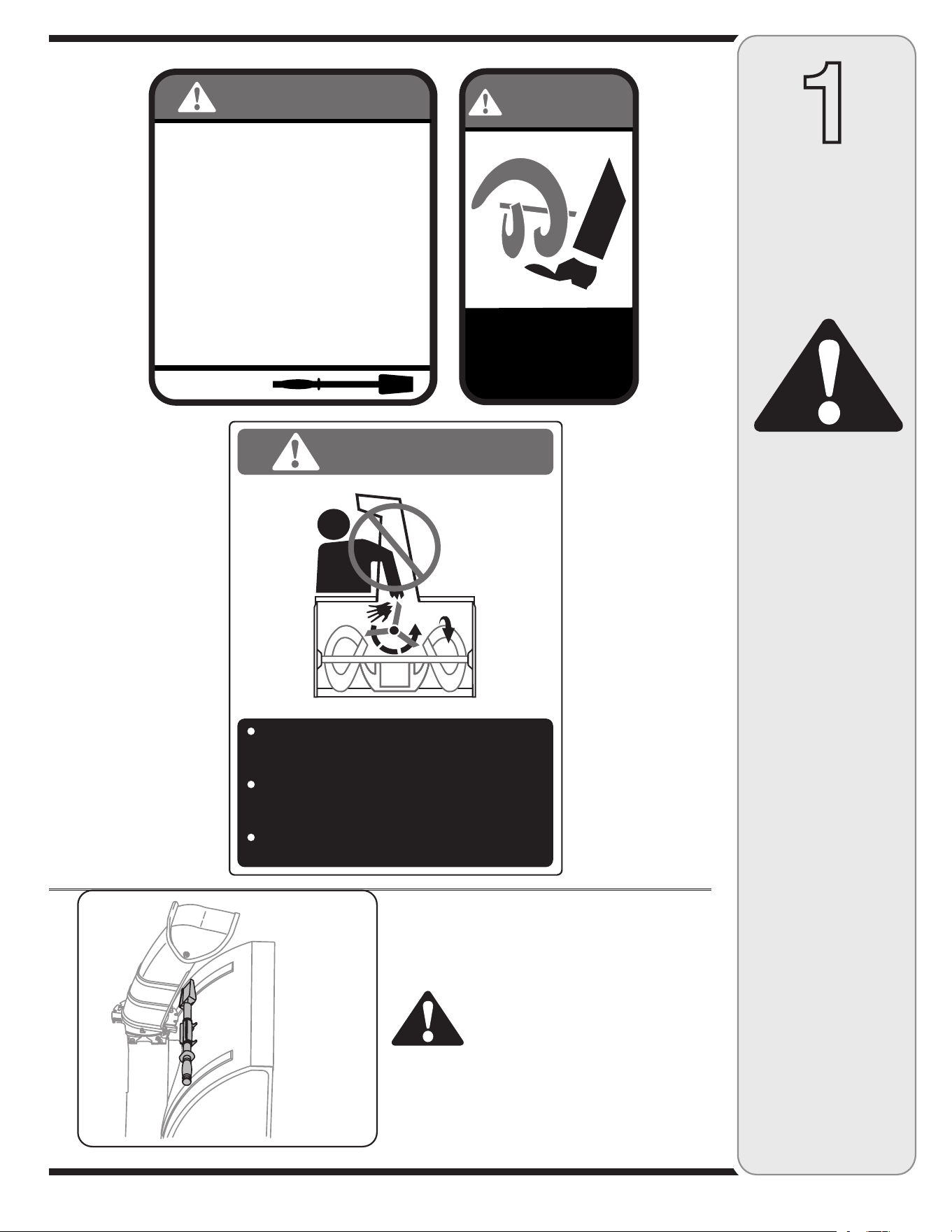
A chute clean-out tool is fastened to the top of the
auger housing with a mounting clip. The tool is designed
to clear a chute assembly of ice and snow.
This item is fastened with a cable tie at the factory. Cut
the cable tie before operating the snow thrower.
WARNING: Never use your
hands to clear a clogged chute
assembly. Shut off engine and
remain behind handles until
all moving parts have stopped
before using the clean-out tool
to clear the chute assembly.
4
2
Safe
Operation
Practices
Training
1. Read, understand, and follow all instructions on the
machine and in the manual(s) before attempting to
assemble and operate. Keep this manual in a safe place for
future and regular reference and for ordering replacement
parts.
2. Be familiar with all controls and their proper operation.
Know how to stop the machine and disengage them quickly.
3. Never allow children under 14 years old to operate this
machine. Children 14 years old and over should read and
understand the operation instructions and safety rules in
this manual and should be trained and supervised by a
parent.
4. Never allow adults to operate this machine without proper
instruction.
5. Thrown objects can cause serious personal injury. Plan
your snow-throwing pattern to avoid discharge of material
toward roads, bystanders and the like.
6. Keep bystanders, helpers, pets and children at least 75 feet
from the machine while it is in operation. Stop machine if
anyone enters the area.
7. Exercise caution to avoid slipping or falling, especially
when operating in reverse.
Preparation
1. Thoroughly inspect the area where the equipment is to be
used. Remove all doormats, newspapers, sleds, boards,
wires and other foreign objects, which could be tripped over
or thrown by the auger/impeller.
2. Always wear safety glasses or eye shields during operation
and while performing an adjustment or repair to protect your
eyes. Thrown objects which ricochet can cause serious
injury to the eyes.
3. Do not operate without wearing adequate winter outer
garments. Do not wear jewelry, long scarves or other
loose clothing, which could become entangled in moving
parts. Wear footwear which will improve footing on slippery
surfaces.
4. Use a grounded three-wire extension cord and receptacle
for all units with electric start engines.
5. Adjust collector housing height to clear gravel or crushed
rock surfaces.
6. Disengage all control levers before starting the engine.
7. Never attempt to make any adjustments while engine is
running, except where specifically recommended in the
operator’s manual.
8. Let engine and machine adjust to outdoor temperature
before starting to clear snow.
9. To avoid personal injury or property damage use extreme
care in handling gasoline. Gasoline is extremely flammable
and the vapors are explosive. Serious personal injury can
occur when gasoline is spilled on yourself or your clothes,
which can ignite. Wash your skin and change clothes
immediately.
a. Use only an approved gasoline container.
b. Extinguish all cigarettes, cigars, pipes and other sources
of ignition.
c. Never fuel machine indoors.
d. Never remove gas cap or add fuel while the engine is hot
or running.
e. Allow engine to cool at least two minutes before refuel
-
ing.
f. Never over fill fuel tank. Fill tank to no more than ½ inch
below bottom of filler neck to provide space for fuel
expansion.
g. Replace gasoline cap and tighten securely.
h. If gasoline is spilled, wipe it off the engine and equip
-
ment. Move machine to another area. Wait 5 minutes
before starting the engine.
i. Never store the machine or fuel container inside where
there is an open flame, spark or pilot light (e.g. furnace,
water heater, space heater, clothes dryer etc.).
j. Allow machine to cool at least 5 minutes before storing.
WARNING: Engine Exhaust, some of its constituents, and certain vehicle compo-
nents contain or emit chemicals known to State of California to cause cancer and
birth defects or other reproductive harm.
WARNING
This symbol points
out important safety
instructions which, if
not followed, could
endanger the personal
safety and/or property
of yourself and others.
Read and follow all
instructions in this
manual before at-
tempting to operate
this machine. Failure
to comply with these
instructions may result
in personal injury. When
you see this symbol.
HEED ITS WARNING!
Your Responsibility
Restrict the use
of this power machine
to persons who read,
understand
and follow the warnings
and instructions
in this manual
and on the machine.
DANGER: This machine was built to be operated according to the rules for safe operation in this
manual. As with any type of power equipment, carelessness or error on the part of the operator can
result in serious injury. This machine is capable of amputating hands and feet and throwing objects.
Failure to observe the following safety instructions could result in serious injury or death.

5
Operation
1. Do not put hands or feet near rotating parts, in the
auger/impeller housing or chute assembly. Contact with the
rotating parts can amputate hands and feet.
2. The auger/impeller control lever is a safety device. Never
bypass its operation. Doing so makes the machine unsafe
and may cause personal injury.
3. The control levers must operate easily in both directions
and automatically return to the disengaged position when
released.
4. Never operate with a missing or damaged chute assembly.
Keep all safety devices in place and working.
5. Never run an engine indoors or in a poorly ventilated area.
Engine exhaust contains carbon monoxide, an odorless and
deadly gas.
6. Do not operate machine while under the influence of alcohol
or drugs.
7. Muffler and engine become hot and can cause a burn. Do
not touch.
8. Exercise extreme caution when operating on or crossing
gravel surfaces. Stay alert for hidden hazards or traffic.
9. Exercise caution when changing direction and while operat
-
ing on slopes.
10. Plan your snow-throwing pattern to avoid discharge towards
windows, walls, cars etc. Thus, avoiding possible property
damage or personal injury caused by a ricochet.
11. Never direct discharge at children, bystanders and pets or
allow anyone in front of the machine.
12. Do not overload machine capacity by attempting to clear
snow at too fast of a rate.
13. Never operate this machine without good visibility or light.
Always be sure of your footing and keep a firm hold on the
handles. Walk, never run.
14. Disengage power to the auger/impeller when transporting or
not in use.
15. Never operate machine at high transport speeds on slippery
surfaces. Look down and behind and use care when
backing up.
16. If the machine should start to vibrate abnormally, stop the
engine, disconnect the spark plug wire and ground it against
the engine. Inspect thoroughly for damage. Repair any
damage before starting and operating.
17. Disengage all control levers and stop engine before you
leave the operating position (behind the handles). Wait
until the auger/impeller comes to a complete stop before
unclogging the chute assembly, making any adjustments, or
inspections.
18. Never put your hand in the discharge or collector openings.
Always use the clean-out tool provided to unclog the dis-
charge opening. Do not unclog chute assembly while engine
is running. Shut off engine and remain behind handles until
all moving parts have stopped before unclogging.
19. Use only attachments and accessories approved by the
manufacturer (e.g. wheel weights, tire chains, cabs etc.).
20. If situations occur which are not covered in this manual,
use care and good judgment. Contact your dealer for
assistance.
Maintenance & Storage
1. Never tamper with safety devices. Check their proper
operation regularly. Refer to the maintenance and adjust-
ment sections of this manual.
2. Before cleaning, repairing, or inspecting machine disen
-
gage all control levers and stop the engine. Wait until the
auger/impeller come to a complete stop. Disconnect the
spark plug wire and ground against the engine to prevent
unintended starting.
3. Check bolts and screws for proper tightness at frequent
intervals to keep the machine in safe working condition.
Also, visually inspect machine for any damage.
4. Do not change the engine governor setting or over-speed
the engine. The governor controls the maximum safe
operating speed of the engine.
5. Snow thrower shave plates and skid shoes are subject to
wear and damage. For your safety protection, frequently
check all components and replace with original equipment
manufacturer’s (OEM) parts only. “Use of parts which do
not meet the original equipment specifications may lead to
improper performance and compromise safety!”
6. Check controls periodically to verify they engage and
disengage properly and adjust, if necessary. Refer to the
adjustment section in this operator’s manual for instructions.
7. Maintain or replace safety and instruction labels, as neces
-
sary.
8. Observe proper disposal laws and regulations for gas, oil,
etc. to protect the environment.
9. Prior to storing, run machine a few minutes to clear snow
from machine and prevent freeze up of auger/impeller.
10. Never store the machine or fuel container inside where
there is an open flame, spark or pilot light such as a water
heater, furnace, clothes dryer etc.
11. Always refer to the operator’s manual for proper instructions
on off-season storage.
Do not modify engine
To avoid serious injury or death, do not modify engine in any
way. Tampering with the governor setting can lead to a runaway
engine and cause it to operate at unsafe speeds. Never tamper
with factory setting of engine governor.
Notice regarding Emissions
Engines which are certified to comply with California and federal
EPA emission regulations for SORE (Small Off Road Equipment)
are certified to operate on regular unleaded gasoline, and may
include the following emission control systems: Engine Modifica-
tion (EM) and Three Way Catalyst (TWC) if so equipped.
Your Responsibility
Restrict the use of this power machine to persons who read, un-
derstand and follow the warnings and instructions in this manual
and on the machine.
2
Safe
Operation
Practices
WARNING
This symbol points
out important safety
instructions, which if
not followed, could
endanger the personal
safety and/or property
of yourself and others.
Read and follow all
instructions in this man-
ual before attempting to
operate this machine.
Failure to comply with
these instructions may
result in personal injury.
When you see this
symbol.
HEED IT’S WARNING!
Your Responsibility
Restrict the use
of this power machine
to persons who read,
understand
and follow the warnings
and instructions
in this manual
and on the machine.
6
3
Setting Up
Your Snow
Thrower
NOTE: All references
in this manual to the
left or right side of the
snow thrower is from
the operating position
only. Exceptions, if any,
will be specified.
IMPORTANT
This unit is shipped
with the engine full of
oil. After assembly,
refer to the Tecumseh
Engines manual
packed separately with
your snow thrower
for fuel and oil fill-up
details.
IMPORTANT: Two replacement auger shear pins are
included with this manual. Refer to the Maintenance
section for more information regarding shear pin replace-
ment.
NOTE: All references in this manual to the left or right
side of the snow thrower is from the operating position
only. Exceptions, if any, will be specified.
IMPORTANT: This unit is shipped with the engine full of
oil. After assembly, refer to the Tecumseh Engine manual
packed separately with your snow thrower for fuel and oil
fill-up details.
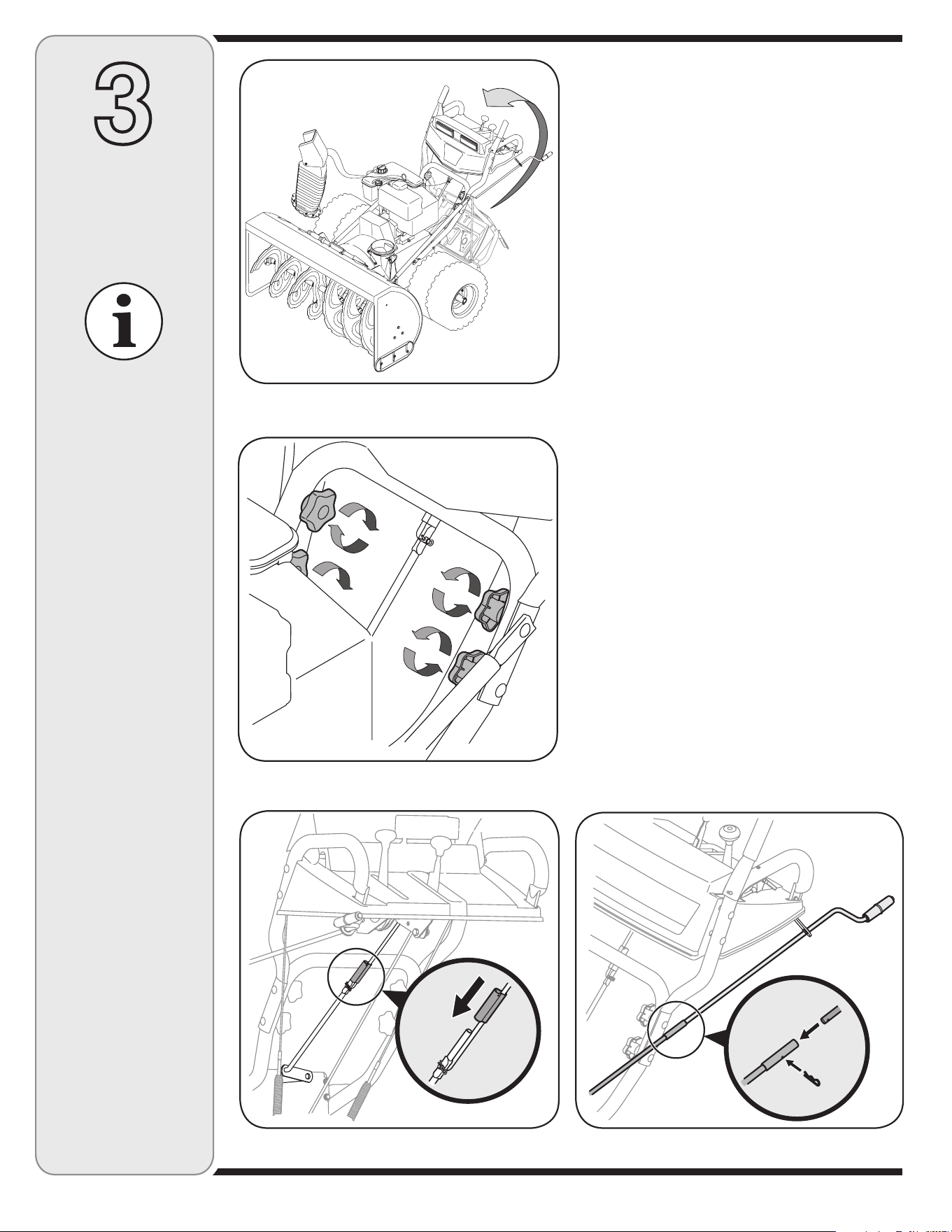
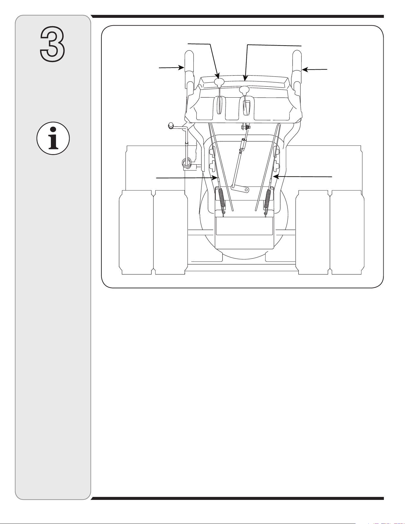
1. Observe the lower area of the snow thrower to be sure
that all cables (steering, auger, and drive) are properly
routed and not pinched or kinked before pivoting
handle upward.
a. Remove the lower star knob and carriage bolt from
each side of the lower handle. Pull up and back on
upper handle as shown in Figure 3-1. Align upper
handle with the lower handle. Make certain the
springs at the lower end of the auger and drive
cables are securely hooked into their respective
actuator bracket.
2. a. Secure the upper handle and lower handle with the
two star knobs and carriage bolts removed earlier.
See Figure 3-2.
b. Tighten the two star knobs already installed in the
upper holes to firmly secure the upper handle and
support tubes.
3. Align the upper and lower shift rods, then slide the
shift rod connector down over the end of the lower
shift rod. Tap the connector until the lower rod is
completely through the connector. See Figure 3-3.
NOTE: If the connector is not properly assembled, the
shift rod will pivot and you will not be able to change
speeds or direction.
Figure 3-2
Figure 3-1
Figure 3-3 Figure 3-4
a
b
Specifications are
subject to change
without notification
or obligation. Images
may not reflect your
exact model and are for
reference purposes only.
7
3
Setting Up
Your Snow
Thrower
IMPORTANT
Prior to operating
your snow thrower,
refer to Auger Control
Test in the Operation
section. Read and
follow all instructions
carefully and perform
all adjustments to verify
your snow thrower is
operating safely and
properly.
Figure 3-6
Figure 3-8
Figure 3-7
NOTE: If the full range of speeds (forward and reverse)
can not be achieved, refer to the “Making Adjustments”
section.
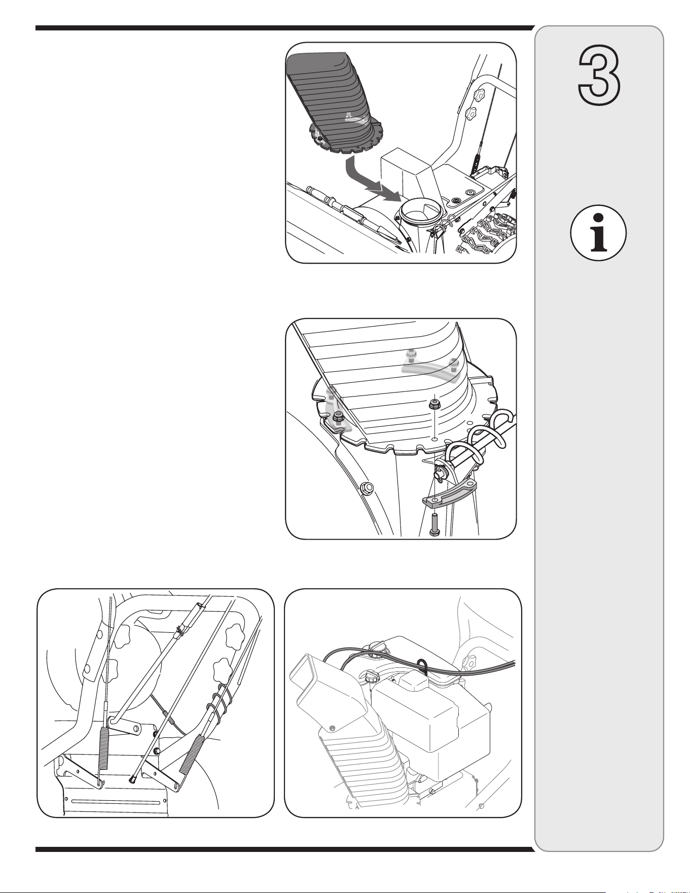
4. a. Remove the internal cotter pin from the upper chute
crank. Slide the upper chute crank into the sleeve
on the lower chute crank.
b. Align the hole in the upper chute crank with the
hole in the sleeve (If necessary, use a pair of pliers
to assist in aligning holes). Insert the internal cotter
pin through the holes to secure the chute crank.
See Figure 3-4.
5. Remove lock nuts and screws securing one of the
flange keepers to the chute assembly.
6. Place chute assembly onto chute base as shown in
Figure 3-5, making sure that the notches engage with
the spiral end of chute directional control.
7. Secure flange keeper removed earlier with lock nuts
and screws. Tighten down nuts securing the other two
flange keepers. See Figure 3-6.
8. If not already done, slip the cables that run from the
handle panel to the discharge chute into the cable
guide located on top of the engine. See Figure 3-7.
9. If not already done, wrap the wire of the head lamp
wire harness down the right handle until the wire can
be plugged into the engine alternator wire connector
down on the engine. See Figure 3-8.
10. Normally the cable ties holding the steering cables
against the handle are loosely installed on each side
of the lower handle at the factory. Pull the cable ties
tight to secure. Cut the excess from the ends of cable
ties.
The extension cord is fastened with a cable tie to the rear
of the auger housing for shipping purposes. Cut the cable
tie and remove it before operating the snow thrower.
Figure 3-5
8
3
Setting Up
Your Snow
Thrower
Final Adjustments
Make these final assembly adjustments before
operating your snow thrower for the first time. Failure
to follow these instructions may cause damage to the
snow thrower.
Testing Drive Control & Shift Lever
Refer to Figure 3-9 for location of controls.
1. Move the shift lever into sixth (6) position.
2. With the wheel drive control released, push the
snow thrower forward, then pull it back. The machine
should move freely.
3. Engage the drive control and attempt to move the
machine both forward and back, resistance should
be felt.
4. Move the shift lever into the fast reverse (R2)
position and repeat the previous two steps.
If you experienced resistance rolling the unit, either
when repositioning the shift lever from 6 to R2 or when
attempting to move the machine with the drive control
released, adjust the drive control immediately. See
Adjusting Drive and Auger Controls.
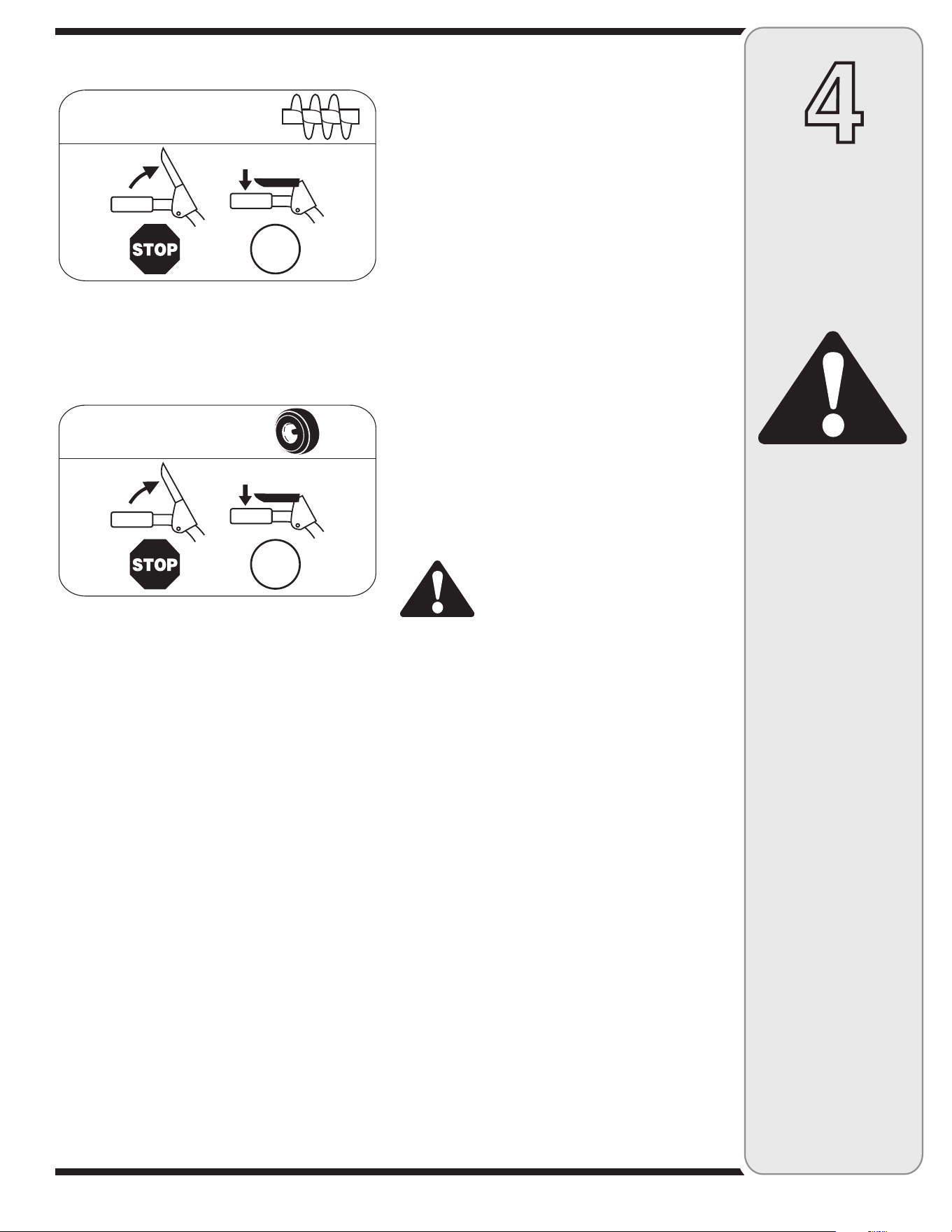
Testing Auger Drive Control
When the auger control is released and in the disengaged
“up” position, the cable should have very little slack, but
should NOT be tight.
1. In a well-ventilated area, start the snow thrower
engine as instructed in the Operation section. Make
sure the throttle is set in the fast position.
2. While standing in the operator’s position (behind the
snow thrower), engage the auger control and allow
the auger to remain engaged for approximately ten
seconds before releasing the auger control. Repeat
this several times.
3. With the engine running in the fast position and the
auger control in the disengaged “up” position, walk to
the front of the machine.
Confirm that the auger has completely stopped
rotating and shows no signs of motion.
4. If the auger shows any signs of rotating, immediately
return to the operator’s position and shut off the
engine. Wait for all moving parts to stop before
readjusting the auger control cable.
Figure 3-9
Drive
Control
Drive
Control
Cable
Auger
Control
Auger
Control
Cable
Shift Lever
Chute Tilt Control
Specifications are
subject to change
without notification
or obligation. Images
may not reflect your
exact model and are
for reference purposes
only.
9
3
Setting Up
Your Snow
Thrower
IMPORTANT: Under any
circumstance do not
exceed manufacturer’s
recommended psi. Equal
tire pressure should be
maintained at all times.
Excessive pressure when
seating beads may cause
tire/rim assembly to burst
with force sufficient to
cause serious injury.
Refer to sidewall of tire for
recommended pressure.
WARNING
Do not over-tighten the
cable. Over-tightening may
prevent the auger from
disengaging and compro-
mise the safety of the snow
thrower.
Figure 3-10
Adjusting Drive and Auger Controls
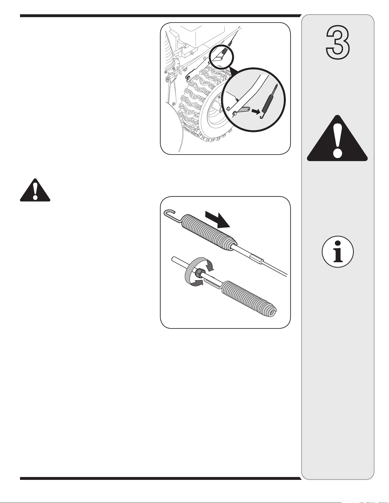
1. From beneath the handle, pull downward on the
appropriate cable and unhook the spring found on the
end of the cable from its respective actuator bracket.
Refer to Figures 3-9 and 3-10.
2. Slide the spring up the cable to expose the cable
coupler threads and lock nut. Refer to Figure 3-11.
Adjust the lock nut as follows:
3. If adjusting the drive cable, thread the lock nut
outward (down the coupler) to lengthen the cable
and allow the unit to move freely when the control is
released. Thread the lock nut inward (up the coupler)
to shorten the cable to reduce slippage and prevent
the machine from being easily moved with the drive
control engaged.
4. If adjusting the auger cable, thread the lock nut down
to lengthen the cable as necessary to stop the auger
from turning when the control is released.
WARNING: Do not over-tighten the
cable. Over-tightening may prevent the
auger from disengaging and compro-
mise the safety of the snow thrower.
5. Reattach the spring to the actuator bracket.
6. Repeat the wheel drive and auger control tests to
verify proper adjustment. Repeat previous steps if
necessary to attain proper adjustment of each cable.
Tire Pressure (Pneumatic Tires)
The tires are over-inflated for shipping purposes. Check
the tire pressure before operating the snow thrower. Refer
to the tire side wall for tire manufacturer’s recommended
psi and deflate (or inflate) the tires as necessary.
NOTE: If the tire pressure is not equal in both tires, the
unit may pull to one side or the other and the shave plate
will not sit level on the ground.
IMPORTANT: Under any circumstance do not exceed
manufacturer’s recommended psi. Equal tire pressure
should be maintained at all times. Excessive pressure
when seating beads may cause tire/rim assembly to
burst with force sufficient to cause serious injury. Refer to
sidewall of tire for recommended pressure.
Figure 3-11
Specifications are subject
to change without notifica-
tion or obligation. Images
may not reflect your exact
model and are for refer-
ence purposes only.
10
4
Operating
Your Snow
Thrower
WARNING
Read, understand,
and follow all instruc-
tions and warnings
on the machine and
in this manual before
operating.
NOTE: For detailed starting instructions and more
information on all engine controls, refer to the
Tecumseh Engines manual packed separately and
Starting The Engine later in this section.
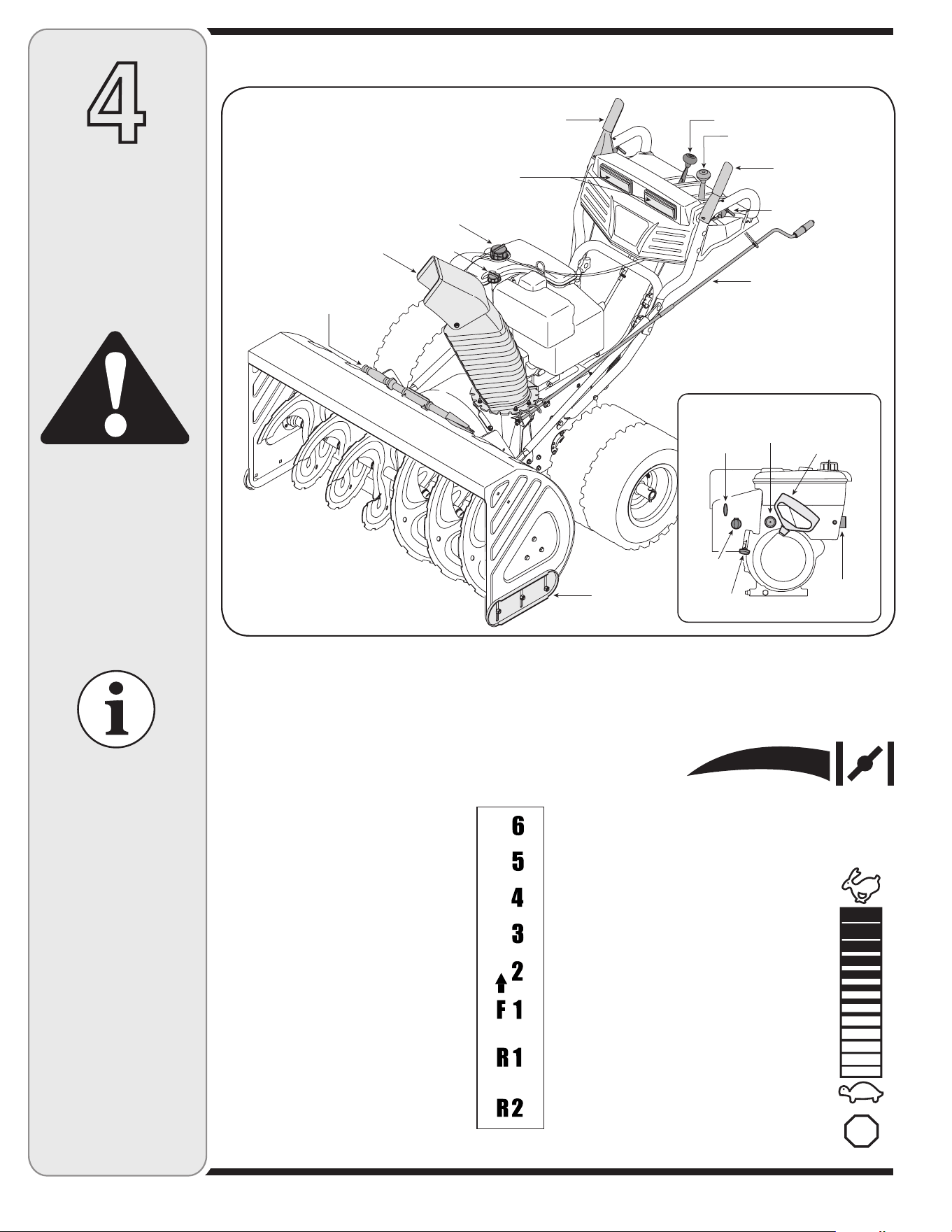
Shift Lever
The shift lever is located in the center of
the handle panel. Place the shift lever
into any of eight positions to control the
direction of travel and ground speed.
Forward
Your snow thrower has six forward (F)
speeds, with position number one (1)
being the slowest speed.
Reverse
Your snow thrower has two reverse (R)
speeds, with position number one (1)
being the slower speed.
Know Your Snow Thrower
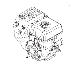
Choke Control
The choke control
is found on the rear
of the engine and is
activated by rotating the knob clockwise. Activating the
choke control closes the choke plate on the carburetor
and aids in starting the engine.
Throttle Control
The throttle control is located on the engine.
It regulates the speed of the engine and
will shut off the engine when pushed down
completely.
Primer
Depressing the primer forces fuel directly into
the engine’s carburetor to aid in cold-weather
starting.
Oil Fill
Engine oil level can be checked and oil added
through the oil fill.
Figure 4-1
34/0
For detailed starting
instructions and
more information on
all engine controls,
refer to the Tecumseh
Engine manual
packed separately.
Now that you have setup your snow thrower, it’s important to become acquainted with its controls and features.
Specifications are
subject to change
without notification
or obligation. Images
may not reflect your
exact model and
are for reference
purposes only.
Headlights
Chute Assembly
Clean-Out Tool
Gas Cap
Oil Fill
Drive Control
Shift Lever
Chute Tilt Control
Auger Control
Wheel Steering
Control
Chute
Directional
Control
Skid Shoe
Engine Controls
Recoil Starter
Handle
Electric
Starter
Outlet
PrimerIgnition
Key
Choke
Control
Throttle
Control
11
4
Operating
Your Snow
Thrower
WARNING
The operation of any
snow thrower can result
in foreign objects being
thrown into the eyes,
which can damage your
eyes severely. Always
wear safety glasses
while operating the snow
thrower, or while perform-
ing any adjustments or
repairs on it.
Be sure no one other than
the operator is standing
near the snow thrower
while starting engine or
operating snow thrower.
Never run engine indoors
or in enclosed, poorly
ventilated areas. Engine
exhaust contains carbon
monoxide, an odorless
and deadly gas. Keep
hands, feet, hair and loose
clothing away from any
moving parts on engine
and snow thrower.
Auger Control
The auger control is located on the left handle. Squeeze
the control grip against the handle to engage the augers
and start snow throwing action. Release to stop.
Drive Control / Auger Lock
The drive control is located on the right handle. Squeeze
the control grip against the handle to engage the wheel
drive. Release to stop.
The drive control also locks the auger control so you can
operate the chute directional control without interrupting
the snow throwing process. If the auger control is en-
gaged simultaneously with the drive control, the operator
can release the auger control (on the left handle) and
the augers will remain engaged. Release both controls to
stop the augers and wheel drive.
IMPORTANT: Always release the drive control before
changing speeds.
Chute Tilt Control
The distance snow is thrown can be changed by adjust-
ing the angle of the chute assembly. Move the chute tilt
control forward to decrease the distance, toward the rear
to increase.
Chute Directional Control
The chute directional control is located on the left side of
the snow thrower.
• To change the direction in which snow is thrown,
crank clockwise to discharge to the left and counter-
clockwise to discharge to the right.
Wheel Steering Controls
The left and right wheel steering controls are located on
the underside of the handles. Squeeze the right control to
turn right; squeeze the left control to turn left.
NOTE: Operate the snow thrower in open areas until you
are familiar with these controls.
Ignition Key
The ignition key must be inserted and snapped in place
in order for the engine to start. Remove the ignition key to
prevent unauthorized use of equipment. Do NOT attempt
to turn the key.
Clean-Out Tool
The clean-out tool is mounted to the rear of the auger
housing and is designed to clear a clogged chute. Refer
to Using Clean-Out Tool later in this section for instruc-
tions on how to properly use it.
WARNING: Never use your hands to
clear a clogged chute assembly. Shut
off engine and remain behind handles
until all moving parts have stopped
before unclogging.
NOTE: The clean-out tool is fastened to the rear of the
auger housing with a cable tie. Cut the cable tie before
operating the snow thrower.
Skid Shoes
Position the skid shoes based on surface conditions.
Adjust upward for hard-packed snow. Adjust downward
when operating on gravel or crushed rock surfaces.
!5'%2
#/.42/,
'/
$2)6%
#/.42/,
'/
12
WARNING
Use extreme care when
handling gasoline.
Gasoline is extremely
flammable and the vapors
are explosive. Never fuel
the machine indoors or
while the engine is hot
or running. Extinguish
cigarettes, cigars, pipes
and other sources of
ignition.
4
Operating
Your Snow
Thrower
The electric starter is
equipped with a grounded
three-wire power cord
and plug and is designed
to operate on 120 volt AC
household current. It must
be used with a properly
grounded three-prong
receptacle at all times
to avoid the possibility
of electric shock. Follow
all instructions care-
fully prior to operating the
electric starter.
Gas & Oil Fill-Up
Service the engine with gasoline and oil as instructed in
the Tecumseh Engines manual packed separately with
your snow thrower. Read instructions carefully.
WARNING: Use extreme care when
handling gasoline. Gasoline is
extremely flammable and the vapors
are explosive. Never fuel machine indoors or while
the engine is hot or running. Extinguish cigarettes,
cigars, pipes and other sources of ignition.
Starting the Engine
1. Attach spark plug wire to spark plug. Make certain
the metal loop on the end of the spark plug wire
(inside the rubber boot) is fastened securely over the
metal tip on the spark plug.
2. Make certain both the auger control and drive control
are in the disengaged (released) position.
3. Move throttle control up to FAST position. Insert
ignition key into slot. Make sure it snaps into place.
Do not attempt to turn the key.
NOTE: The engine cannot start unless the key is
inserted into ignition switch. Do not turn the key.
Electric Starter
1. Determine that your home’s wiring is a three-wire
grounded system. Ask a licensed electrician if you
are not certain.
WARNING: The optional electric
starter is equipped with a grounded
three-wire power cord and plug, and
is designed to operate on 120 volt AC
household current. It must be used with a properly
grounded three-prong receptacle at all times to
avoid the possibility of electric shock. Follow all
instructions carefully prior to operating the electric
starter.
If your house wiring system is not a three-wire
grounded system, do not use this electric starter under
any conditions.
If your home electrical system is grounded, but a
three-hole receptacle is not available, one should
be installed by a licensed electrician before using the
electric starter.
If you have a grounded three-prong receptacle,
proceed as follows:
1. Plug the extension cord into the outlet located on the
engine’s surface. Plug the other end of extension cord
into a three-prong 120-volt, grounded, AC outlet in a
well-ventilated area.
2. Rotate choke control to FULL choke position (for a cold
engine start).
NOTE: If the engine is already warm, place choke control
in the OFF position instead of FULL.
3. Push the primer two or three times for cold engine
start, making sure to cover vent hole in the center of
the primer when pushing.
NOTE: DO NOT use primer to restart a warm engine after
a short shutdown.
4. Push starter button to start engine.
5. Once the engine starts, immediately release starter
button.
6. As the engine warms, slowly rotate the choke control
to the OFF position. If the engine falters, quickly rotate
the choke control back to FULL and then slowly into
the OFF position again.
7. When disconnecting the extension cord, always unplug
the end at the three-prong wall outlet before unplug-
ging the opposite end from the snow thrower.
Recoil Starter
1. Rotate choke control to FULL choke position (cold
engine start).
NOTE: If the engine is already warm, place choke control
in the OFF position instead of FULL.
2. Push the primer two or three times for cold engine
start, making sure to cover vent hole in the center of
the primer when pushing.
NOTE: DO NOT use primer to restart a warm engine after
a short shutdown.
NOTE: Additional priming may be necessary if the
temperature is below 15° Fahrenheit.
3. Grasp the recoil starter handle and slowly pull the rope
out. At the point where it becomes slightly harder to
pull the rope, slowly allow the rope to recoil.
4. Pull the starter handle with a firm, rapid stroke. Do not
release the handle and allow it to snap back. Keep a
firm hold on the starter handle and allow it to slowly
recoil.
13
WARNING
The muffler, engine,
and surrounding
areas become hot
and can cause a
burn. Do not touch.
4
Operating
Your Snow
Thrower
NOTE: Use slower
speeds in higher snow
and/or until you are
familiar with the snow
thrower operation.
IMPORTANT
NEVER move the
shift lever without first
releasing the wheel
drive control. Doing so
will cause premature
wear on the drive
system’s friction wheel.
5. As the engine warms, slowly rotate the choke control
to the OFF position. If the engine falters, quickly
rotate the choke control back to the FULL position
and then slowly into the OFF position again.
NOTE: Allow the engine to warm up for a few minutes
after starting. The engine will not develop full power until
it reaches operating temperatures.
Stopping the Engine
Run engine for a few minutes before stopping to help dry
off any moisture on the engine.
1. Move throttle control to STOP position.
2. Remove the ignition key (do not turn key) to prevent
unauthorized use of equipment.
3. Wipe all snow and moisture from the area around the
engine as well as the area in and around the drive
control and auger control. Also, engage and release
both controls several times.
NOTE: Keep the key in a safe place. The engine cannot
start without the ignition key.
To Engage Drive
1. With the engine running near top speed, move
shift lever to one of six FORWARD positions or two
REVERSE positions. Select a speed appropriate for
the snow conditions that exist.
NOTE: Use slower speeds in higher snow and/or until
you are familiar with the snow thrower operation.
2. Squeeze drive control against the right handle and
the snow thrower will move. Release it and the drive
motion will stop.
IMPORTANT: NEVER move the shift lever without first
releasing the wheel drive control. Doing so will cause
premature wear on the drive system’s friction wheel.
3. To turn the unit left or right, squeeze the respective
wheel steering control. See Figure 4-1.
To Engage Augers
1. To engage augers and start snow throwing, squeeze
the left hand auger control against the left handle.
Release to stop augers.
2. While the auger control is engaged, squeeze the drive
control to move, release to stop. Do not shift speeds
while the drive is engaged.
NOTE: This same lever also locks auger control so you
can turn the chute control without interrupting the snow
throwing process.
3. Release the auger control; the interlock mechanism
should keep the auger control engaged until the drive
control is released.
4. Release the drive control to stop both the augers and
the wheel drive. To stop the auger, both levers must
be released.
Operating Tips
NOTE: Allow the engine to warm up for a few minutes.
The engine will not develop full power until it reaches
operating temperature.
WARNING: The temperature of the
muffler and the surrounding areas may
exceed 150° F. Avoid these areas.
• If possible, remove snow immediately after it falls.
• Discharge snow downwind whenever possible.
• Slightly overlap each previous path.
• Set the skid shoes 1/4-inch below the shave plate for
normal usage. Adjust them upward for hard-packed
snow and downward when using on gravel or crushed
rock.
Chute Clean-Out Tool
The chute clean-out tool is conveniently fastened to the
rear of the auger housing with a mounting clip. Should
snow and ice become lodged in the chute assembly
during operation, proceed as follows to safely clean the
chute assembly and chute opening:
1. Release both the Auger Control and the Drive Control.
2. Stop the engine by removing the ignition key.
3. Remove the clean-out tool from the clip which secures
it to the rear of the auger housing. See Figure 4-1.
4. Use the shovel-shaped end of the clean-out tool to
dislodge and scoop any snow and ice which has
formed in and near the chute assembly.
5. Refasten the clean-out tool to the mounting clip on
the rear of the auger housing, reinsert the ignition key,
and start the snow thrower’s engine.
6. While standing in the operator’s position (behind the
snow thrower), engage the auger control for a few
seconds to clear any remaining snow and ice from the
chute assembly.
14
5
Making
Adjustments
WARNING
Read, understand, and
follow all instructions
and warnings on the
machine and in this
manual before operat-
ing.
Never attempt to
make any adjustments
while the engine is
running, except where
specified in operator’s
manual.
Shift Rod
If the full range of speeds (forward and reverse) cannot
be achieved, refer to the figure above and adjust the
shift rod as follows:
1. Looking underneath the handle panel, note which
of the three holes in the shift lever the ferrule is
inserted into. Also note the direction of insertion.
Remove the internal cotter pin and flat washer from
the ferrule and withdraw the ferrule from the shift
lever. See Figure 5-1.
2. Place shift lever in sixth (6) position or fastest
forward speed.
3. Push shift rod and shift arm assembly down sharply
as far as it will go to put the drive into the fastest
forward position.
4. As necessary, rotate (thread) the ferrule up or down
the shift rod until the ferrule lines up with the hole
from which it was earlier removed. See Figure 5-1.
5. From the direction noted earlier, insert the ferrule into
the proper hole.
6. Reinstall the washer and the internal cotter pin.
Chute Control
The distance snow is thrown can be adjusted by adjusting
the angle of the chute assembly. Refer to “Operating Your
Snow Thrower” for instructions.
The remote chute control cables have been pre-adjusted
at the factory. Move the remote chute lever on the control
panel back and forward to adjust angle of the chute
assembly.
Drive Control
Refer to the Final Adjustment section of the Assembly
instructions to adjust the drive control. To further check
the adjustment, proceed as follows:
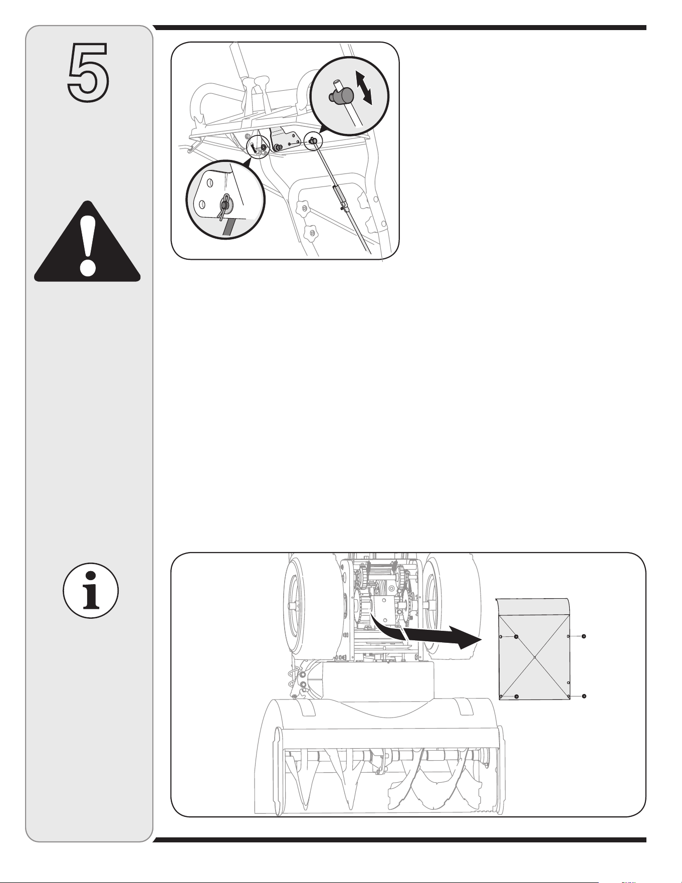
1. With the snow thrower tipped forward (be certain to
drain gasoline or place plastic film under the gas cap if
the snow thrower has already been operated), remove
the frame cover underneath the snow thrower by
removing the self-tapping screws. See Figure 5-2.
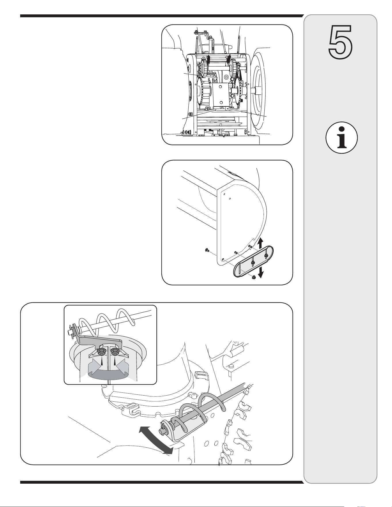
2. Locate the opening between the axle support bracket
and the front frame support (See Figure 5-3). Looking
through this opening, with the drive control released,
there must be 1/8” clearance between the friction
wheel and the drive plate in all positions of the shift
lever.
3. With the drive control engaged, the friction wheel must
contact the drive plate. See Figure 5-3.
4. If there is no friction wheel clearance, or the friction
wheel does not solidly contact the drive plate, re-
adjust the lock nut on the lower end of the drive cable
following the instructions in the Assembly section.
5. Reassemble the frame cover.
Figure 5-1
Figure 5-2
Specifications are
subject to change
without notification
or obligation. Images
may not reflect your
exact model and are
for reference purposes
only.
15
5
Making
Adjustments
IMPORTANT: It is not
recommended that
you operate this snow
thrower on gravel as
loose gravel can be
easily picked up and
thrown by the auger
causing personal
injury or damage to
the snow thrower.
If for some reason,
you have to operate
the snow thrower on
gravel, keep the skid
shoe in the highest
position for maximum
clearance between the
ground and the shave
plate.
Figure 5-3
Figure 5-4
Figure 5-5
Axle Supp.
Brkt.
Opening
Drive
Plate
Friction
Wheel
NOTE: If you placed plastic film under the gas cap earlier,
remove it now.
Skid Shoes
The space between the shave plate and the ground can
be adjusted. For close snow removal, place skid shoes in
the low position. Use a middle or high position when area
to be cleared is uneven.
1. Adjust skid shoes by loosening the six lock nuts and
carriage bolts, and moving skid shoes to desired
position. See Figure 5-4.
2. Make certain the entire bottom surface of skid shoes
are against the ground to avoid uneven wear on the
skid shoes.
3. Tighten nuts and bolts securely.
Chute Bracket Adjustment
If the spiral at the bottom of the chute directional control
is not fully engaging with the chute assembly, the chute
bracket can be adjusted. To do so:
1. Loosen the two nuts which secure the chute bracket
and reposition it slightly. See Figure 5-5.
2. Retighten the nuts.
Auger Control
To adjust the auger control, refer to the section in this
manual titled “Setting Up Your Snow Thrower”.
Specifications are
subject to change
without notification
or obligation. Images
may not reflect your
exact model and
are for reference
purposes only.
16
6
Maintaining
Your Snow
Thrower
WARNING
Always stop engine,
disconnect spark
plug, and ground
against engine before
performing any type
of maintenance on
your machine.
IMPORTANT
Avoid oil spillage on rub-
ber friction wheel and
aluminum drive plate.
IMPORTANT
NEVER replace the
auger shear pins
with standard pins.
Any damage to the
auger gearbox or other
components, as a result
of doing so, will NOT be
covered by your snow
thrower’s warranty.
Figure 6-1
Figure 6-2
Engine
Refer to the separate Tecumseh Engines manual
packed with your unit for all engine maintenance
instructions.
Lubrication
Engine
Refer to the separate Tecumseh Engines manual
packed with your unit for all engine lubrication
instructions.
Drive and Shifting Mechanism
At least once a season or after every 25 hours of opera-
tion, remove rear cover. Lubricate all chains, sprockets,
gears, bearings, shafts, and the shifting mechanism. Use
engine oil or a spray lubricant. Refer to Figure 6-1.
IMPORTANT: Keep all grease and oil off the rubber
friction wheel and drive plate.
Wheels
At least once a season, remove all wheels. Clean and
coat the axles with a multipurpose automotive grease
before reinstalling wheels.
Chute Directional Control
Once a season, the spiral end on the chute directional
control should be greased with multipurpose automotive
grease.
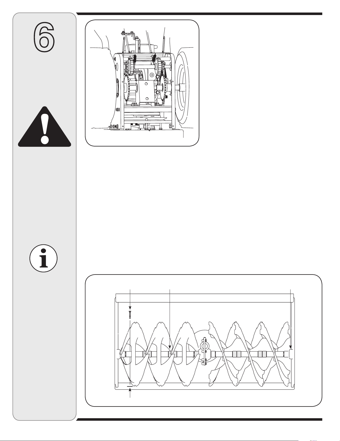
Auger Shaft
At least once a season, remove the shear pins on auger
shaft. Spray lubricant inside shaft, around the spacers.
Also lubricate the flange bearings found at either end of
the shaft. See Figure 6-2.
Augers
The augers are secured to the spiral shaft with shear pins
and cotter pins. See Figure 6-2. If you hit a foreign object
or ice jam, the snow thrower is designed so that the pins
will shear.
1. If augers do not turn, check to see if pins have
sheared.
2. Replace the pins if needed. Two replacement shear
pins and cotter pins have been provided with the
snow thrower. Spray an oil lubricant into shaft before
inserting new pins and securing with new cotter pins.
Shear Pin
Cotter Pin
Spacer Bearing
17
6
Maintaining
Your Snow
Thrower
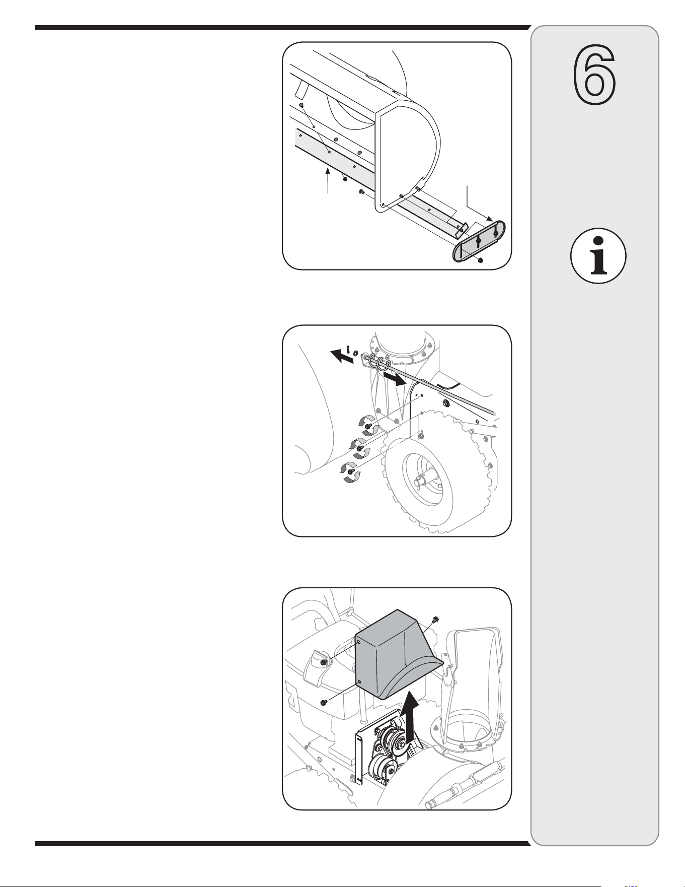
Replacing Belts
1. Disconnect the chute crank assembly at the discharge
chute end by removing the hairpin clip and the flat
washer. Refer to Figure 6-4.
2. Remove the plastic belt cover, located near the
engine, by removing the three self-tapping screws that
secure it. See Figure 6-5.
3. a. Loosen the bolt shown in Figure 6-6 securing the
belt keeper bracket and remove the other bolt.
b. Push the belt keeper and bracket up off the engine
pulley. See Figure 6-7.
Auger Belt
4. Remove the hairpin clip and flat washer from the
ferrule in order to disconnect the auger idler rod from
the brake bracket assembly. See Figure 6-8.
5. Unhook the spring found on the end of the auger
cable from its respective actuator bracket. Refer to
Figure 3-10 in the “Setting Up Your Snow Thrower”
section.
Figure 6-5
Figure 6-4
Figure 6-3
Shave Plate and
Skid Shoes
The shave plate and skid shoes on the bottom of the
snow thrower are subject to wear. Check these periodi-
cally and replace as necessary.
Skid Shoes
NOTE: The skid shoes on this machine have two wear
edges. When one side wears out, they can be rotated
180° to use the other edge.
1. Remove the six carriage bolts and lock nuts that
secure the two skid shoes to the sides of the auger
housing. Refer to Figure 6-3.
2. Position the new skid shoes and secure with the
carriage bolts and nuts. Make certain the skid shoes
are adjusted to be level.
Shave Plate
1. Remove the nuts and carriage bolts that secure the
shave plate to the bottom of the housing, Figure 6-3.
2. Remove the rear most hex nut and carriage bolt
securing the back of each skid shoe to the sides of the
housing. Loosen the remaining hex nuts that secure
the skid shoes.
3. Slide the shave plate out of the off-set slot at the
bottom of the housing, and from between the skid
shoes and side panels of the housing.
4. With the mounting holes toward the back, slide the
new shave plate into position and secure with the
fasteners removed previously.
Specifications are
subject to change
without notification
or obligation. Images
may not reflect your
exact model and
are for reference
purposes only.
Shave Plate
Skid Shoe
18
6
Maintaining
Your Snow
Thrower
Figure 6-8
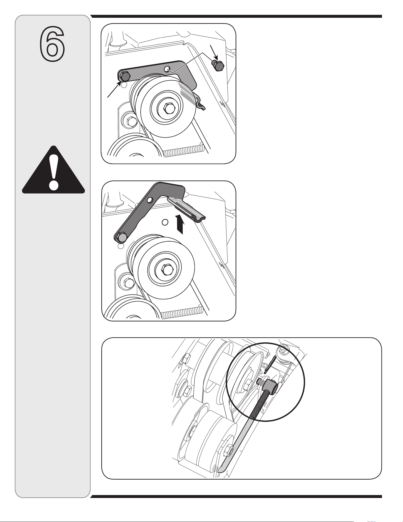
Figure 6-6
Figure 6-7
Loosen
Remove
6. Slip the auger control belt (the front belt) off the
engine pulley.
7. Pull the brake bracket assembly towards the cable
guide roller and unhook the auger cable “Z” fitting.
See Figure 6-9.
8. Remove the upper bolts which attach the auger housing
assembly to the frame assembly using a 9/16” wrench.
Refer to Figure 6-4 on previous page.
9. Place a block of wood underneath the auger housing as
shown in Figure 6-10 and separate auger housing from
the frame by tilting the housing forward and pulling up
the handles.
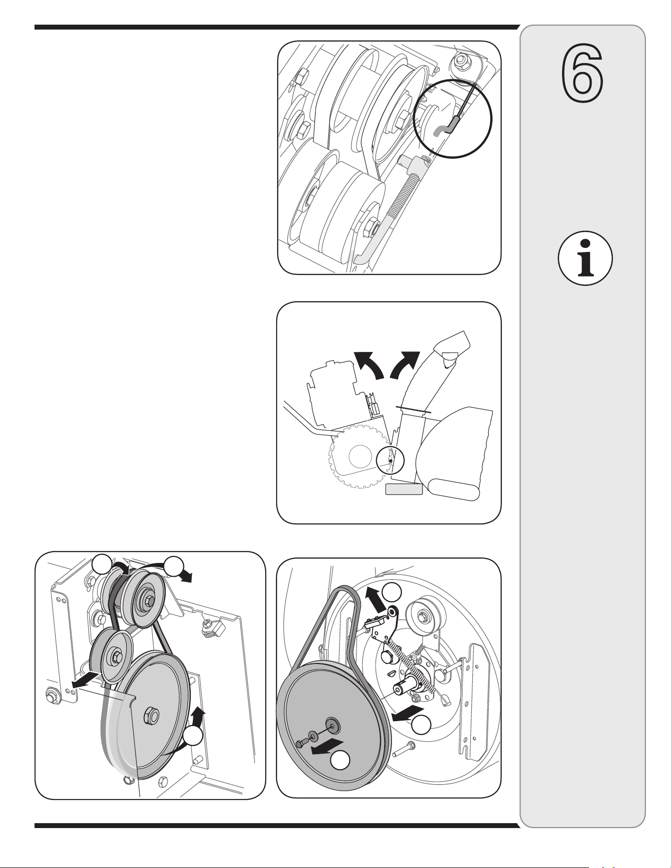
10. a. Using a 1/2” wrench, remove the hex screw and
cupped washer from the center of the pulley on the
auger housing. See Figure 6-11.
b. Lift the brake bracket assembly out of the pulley
groove
c. Remove the pulley. Be careful not to lose the key.
11. Remove and replace auger belt inside belt keepers.
12. Apply Loctite 262 to the threads of the hex screw used
for mounting the auger pulley.
13. Reassemble pulley to auger housing with hex screw
and cupped washer (cupped side toward the pulley).
Torque hex screw 150-250 in. lbs.
NOTE: Make sure key is in place on shaft and brake puck
is seated in the pulley groove.
WARNING
Always stop engine,
disconnect spark
plug, and ground
against engine before
performing any type
of maintenance on
your machine.
19
6
Maintaining
Your Snow
Thrower
Figure 6-12
Figure 6-11
Figure 6-9
Figure 6-10
A
C
B
1
2
3
If also replacing the drive belt, proceed to the “Drive Belt”
instruction. If not, reassemble by performing the previous
steps in the opposite order and manner of removal.
Proper Adjustment: With the auger clutch lever in the
disengaged position, the top surface of the new belt should
be even with the outside diameter of the pulley.
1. To adjust, disconnect ferrule from brake bracket as-
sembly and thread ferrule in (towards idler) to increase
tension on belt, and out to decrease tension.
NOTE: The brake puck must always be firmly seated in the
pulley groove when auger control is disengaged.
Drive Belt
1. Pull the idler pulley away from the backside of the drive
belt to relieve the tension and slide the drive belt off the
idler pulley (If necessary unhook the extension spring
from the belt cover plate). See Figure 6-12.
2. Roll the drive belt off the lower drive pulley.
3. Remove the belt from the engine pulley.
4. Install the new belt on the pulleys in the reverse order and
re-tension with the idler pulley.
5. Reassemble by performing the previous steps in the
opposite order and manner of removal.
Specifications are
subject to change
without notification
or obligation. Images
may not reflect your
exact model and
are for reference
purposes only.
20
6
Maintaining
Your Snow
Thrower
Figure 6-13
Figure 6-14
Remove hex
screw and
washer
Friction wheel assembly
Slide hex shaft out
right side
Hex Shaft
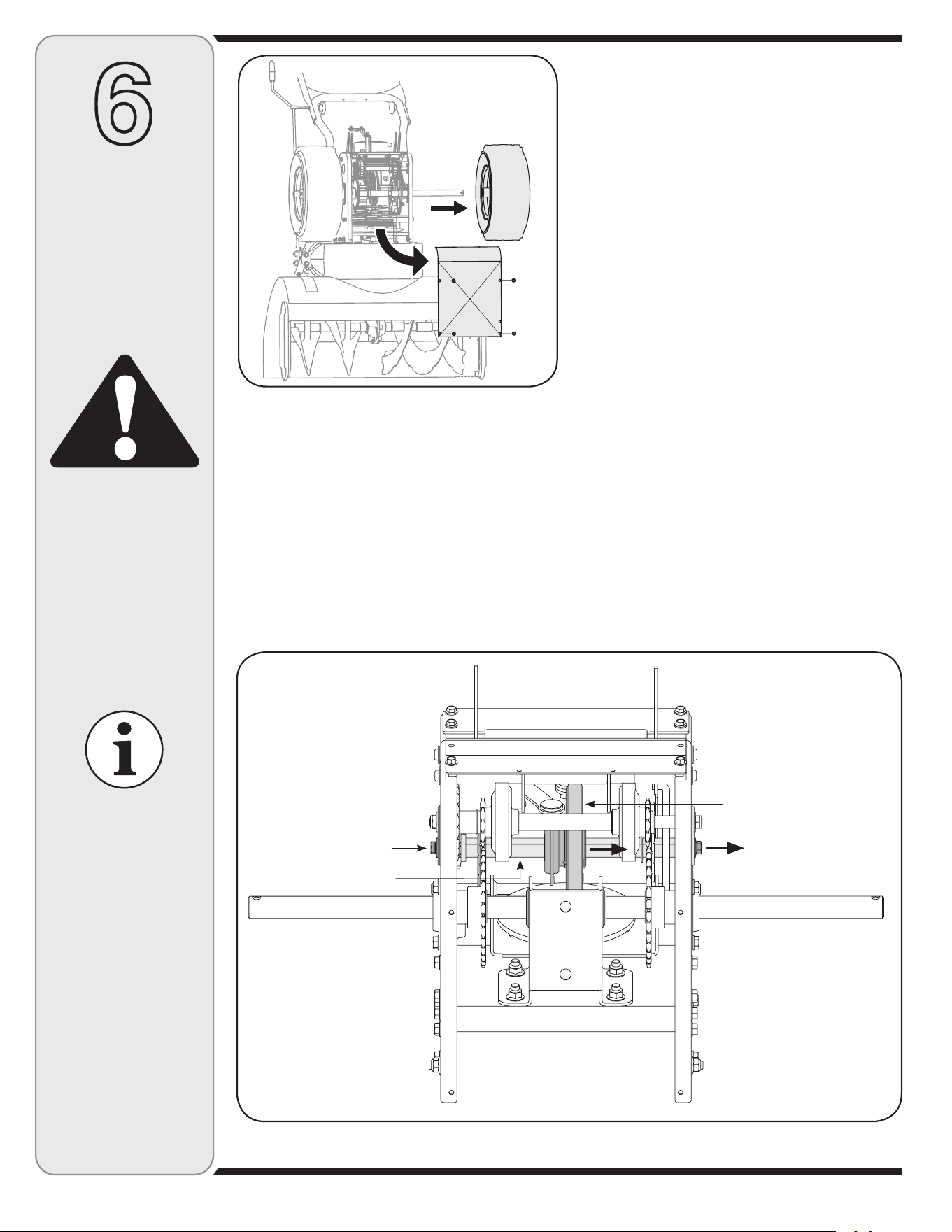
Changing Friction Wheel
The rubber on the friction wheel is subject to wear and
should be checked after the first 25 hours of operation,
and periodically thereafter. Replace the friction wheel if
any signs of wear or cracking are found.
• Drain the gasoline from the snow thrower, or place a
piece of plastic under the gas cap.
• Tip the snow thrower up and forward, so that it rests on
the housing.
• Remove screws from the frame cover underneath the
snow thrower. See Figure 6-13.
• Remove the right wheel from the axle.
• Using a 3/4” wrench, hold the hex shaft and remove
the hex screw and cupped washer and bearing from
left side of the frame. Refer to Figure 6-14.
• Holding the friction wheel assembly, slide the hex shaft
out of the right side of the unit. The spacer on the left
side of the hex shaft will fall and the sprocket should
remain hanging lose in the chain.
• Lift the friction wheel assembly out between the axle
shaft and the drive shaft assemblies.
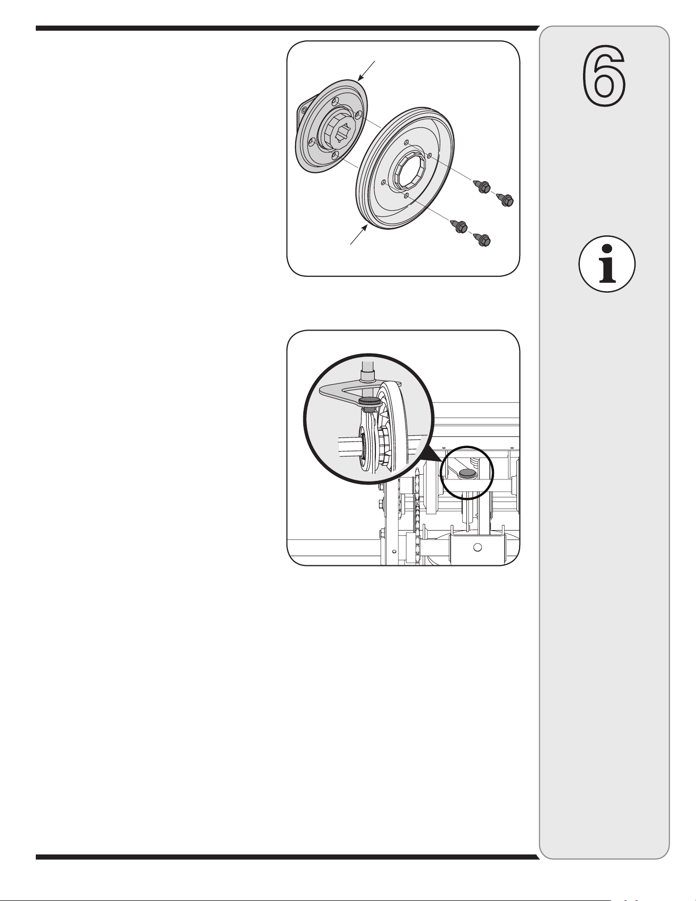
• Remove four screws securing the friction wheel to the
hub assembly. See Figure 6-15. Discard old friction
wheel.
WARNING
Always stop engine,
disconnect spark
plug, and ground
against engine before
performing any type
of maintenance on
your machine.
Specifications are
subject to change
without notification
or obligation. Images
may not reflect your
exact model and are
for reference purposes
only.
21
6
Maintaining
Your Snow
Thrower
Figure 6-16
Friction Wheel
Hub Assembly
Figure 6-15
• Reassemble the new friction wheel to the hub
assembly, tightening the four screws in rotation and
with equal force. It is important to assemble the friction
wheel symmetrically for proper functioning.
• Insert the pin from the shift arm assembly into the
friction wheel assembly and hold assembly in position.
Refer to Figure 6-16.
• Slide the hex shaft through the left side of the housing
and through the friction wheel assembly.
• Insert the hex shaft through the sprocket and the
spacer. Make certain that the chain engages both the
large and the small sprocket.
NOTE:
If the sprocket fell from the snow thrower while
removing the hex shaft, place the sprocket on the hex
shaft. Position the hex hub of the sprocket toward the fric-
tion wheel when sliding the sprocket on to the hex shaft.
• Secure with the cupped washer and hex bolt removed
earlier.
• Secure the frame cover with self-tapping screws. Put
the snow thrower down to its normal operating position.
NOTE: If you placed plastic film under the gas cap, be
certain to remove it.
Specifications are
subject to change
without notification
or obligation. Images
may not reflect your
exact model and
are for reference
purposes only.
18
Preparing Engine
NOTE: Refer to the engine manual for more detailed
information on preparing the snow thrower engine for
storage.
Short-Term Storage
It is important to prevent gum deposits from forming in
essential fuel system parts of the engine such as the
carburetor, fuel filter, fuel hose, or tank during short-term
storage (15-30 days). To prevent this, treat the fuel
system using a fuel stabilizer.
Fuel stabilizer (such as STA-BIL™ or ULTRA-FRESH™)
is an acceptable alternative in minimizing the formation
of fuel gum deposits during storage. Add stabilizer to
gasoline in fuel tank or storage container. Always follow
mix ratio found on stabilizer container. Run engine at least
10 minutes after adding stabilizer to allow it to reach the
carburetor.
WARNING: Never store snow thrower
with fuel in tank indoors or in poorly
ventilated areas, where fuel fumes may
reach an open flame, spark or pilot
light as on a furnace, water heater, clothes dryer or
gas appliance.
CAUTION:
Alcohol blended fuels
(called gasohol or using ethanol or
methanol) can attract moisture which
leads to separation and formation of
acids during storage. Acidic gas can damage the fuel
system of an engine while in storage.
Long-Term Storage
To avoid engine problems, the fuel system should be
emptied before storage for 30 days or longer.
WARNING: Fuel left in engine during
warm weather deteriorates and will
cause serious starting problems.
1. Run the engine until the fuel tank is empty and it stops
due to lack of fuel. Do not attempt to pour fuel from the
engine.
WARNING: Never use engine or carbu-
retor cleaning products in the fuel tank
or permanent damage may occur.
2. Remove the spark plug and pour one (1) ounce of
engine oil through the spark plug hole into the cylinder.
Cover spark plug hole with a rag and crank the engine
several times to distribute the oil. Replace spark plug.
7
Off-Season
Storage
WARNING
Preparing Snow Thrower
• When storing the snow thrower in an unventilated or
metal storage shed, care should be taken to rustproof
the equipment. Using a light oil or silicone, coat the
equipment, especially any chains, springs, bearings
and cables.
• Remove all dirt from exterior of engine and equipment.
• Follow lubrication recommendations.
• Store equipment in a clean, dry area.
If the snow thrower will not be used for 30 days or longer, or if it is the end of the snow season when the last pos-
sibility of snow is gone, the equipment needs to be stored properly. Follow storage instructions below to ensure top
performance from the snow thrower for many more years.
Never store snow thrower
with fuel in tank indoors
or in poorly ventilated
areas, where fuel fumes
may reach an open flame,
spark or pilot light as on
a furnace, water heater,
clothes dryer or
gas appliance.
Fuel left in engine during
warm weather deteriorates
and will cause serious
starting problems.
Never use engine or carbu-
retor cleaning products in
the fuel tank or permanent
damage may occur.

23
This section addresses
minor service issues.
For further details,
contact an authorized
service center.
8
Trouble-
shooting
Cause
Problem
Remedy
Engine fails to start
1. Choke not in ON position.
2. Spark plug wire disconnected.
3. Fuel tank empty or stale fuel.
4. Engine not primed.
5. Faulty spark plug.
6. Blocked fuel line.
7. Safety key not in ignition on engine.
1. Move choke to ON position.
2. Connect wire to spark plug.
3. Fill tank with clean, fresh gasoline.
4. Prime engine as instructed in “Operat
-
ing Your Snow Thrower”.
5. Clean, adjust gap, or replace.
6. Clean fuel line.
7. Insert key fully into the switch.
Engine runs erratic
1. Move choke lever to OFF position.
2. Clean fuel line; fill tank with clean,
fresh gasoline.
3. Drain fuel tank. Refill with fresh fuel.
4. Contact an authorized Service Center.
1. Unit running on CHOKE.
2. Blocked fuel line or stale fuel.
3. Water or dirt in fuel system.
4. Carburetor out of adjustment.
Engine overheats
1. Contact Service Center.1. Carburetor not adjusted properly.
Loss of power
1. Connect and tighten spark plug wire.
2. Remove ice and snow from gas cap.
Be certain vent hole is clear.
3. Contact Service Center.
1. Spark plug wire loose.
2. Gas cap vent hole plugged.
3. Exhaust port plugged.
Unit fails
to propel itself
1. Adjust drive control cable. Refer to
“Making Adjustments”.
2. Replace drive belt.
1. Drive control cable in need of adjust-
ment.
2. Drive belt loose or damaged.
Excessive
Vibration
1. Loose parts or damaged auger.
1. Stop engine immediately and discon
-
nect spark plug wire. Tighten all bolts
and nuts. If vibration continues, have
unit serviced by an authorized Service
Center.
Unit fails
to discharge snow
1. Stop engine immediately and discon-
nect spark plug wire. Clean chute
assembly and inside of auger housing
with clean-out tool or a stick.
2. Stop engine immediately and discon-
nect spark plug wire. Remove object
from auger with clean-out tool or a
stick.
3. Refer to Auger Control Test.
4. Refer to Maintenance section.
5. Replace with new shear pin(s).
1. Chute assembly clogged.
2. Foreign object lodged in auger.
3. Auger control cable in need of adjust-
ment.
4. Auger belt loose or damaged.
5. Shear pin(s) sheared.
24
34
9
49
1
20
2
29
29
63
61
65
63
54
55
68
57
56
59
24
59
54
44
35
40
44
44
29
12
8
8
8
3
3
42
25
7
7
7
44
38
41
20
30
31
21
53
16
6
28
21
13
15
13
46
10
20
10
52
43
47
23
20
14
21
10
10
21
5
26
39
4
32
17
50
33
48
19
22
18
45
37
39
33
11
36
64
66
62
58
67
60
64
67
51
10
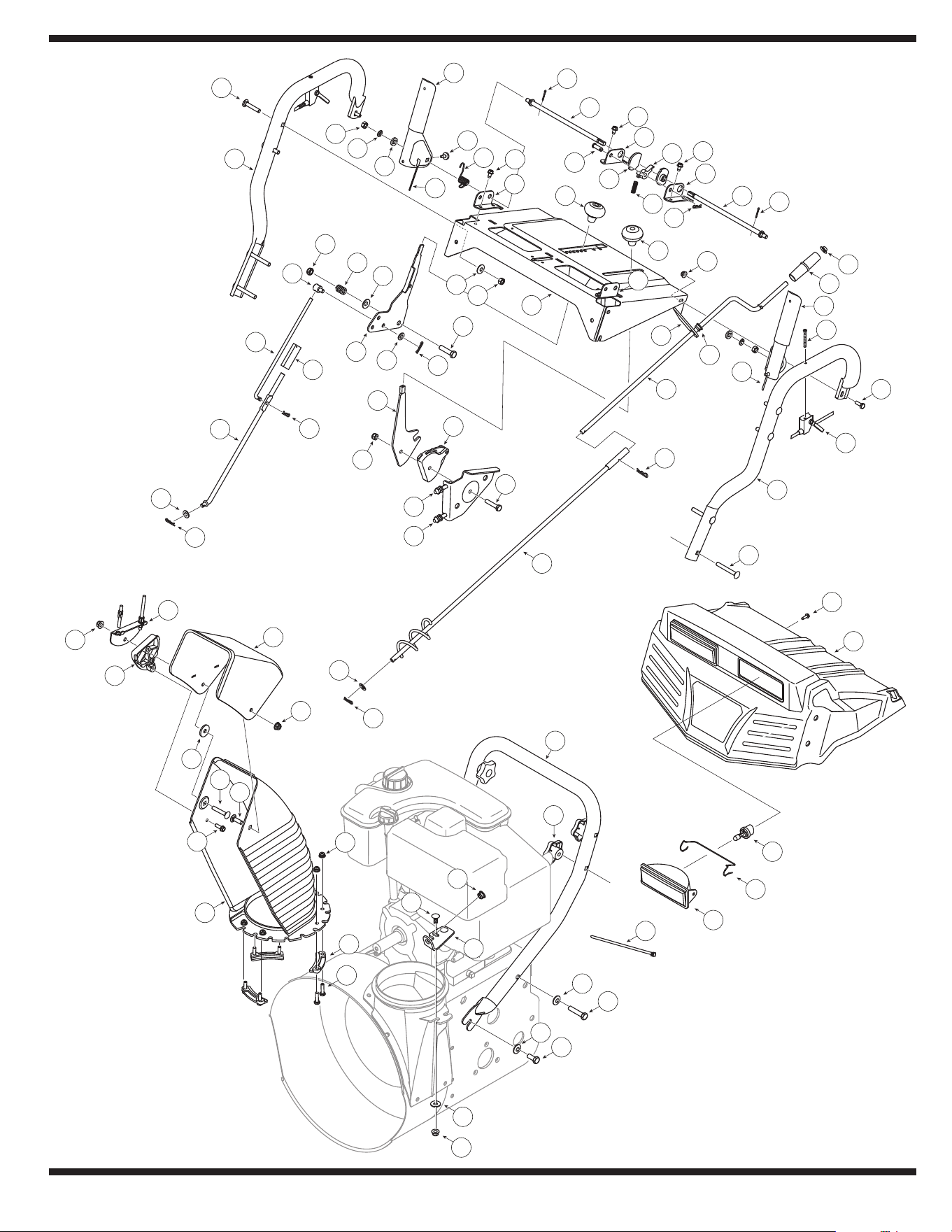
Storm 13045

25
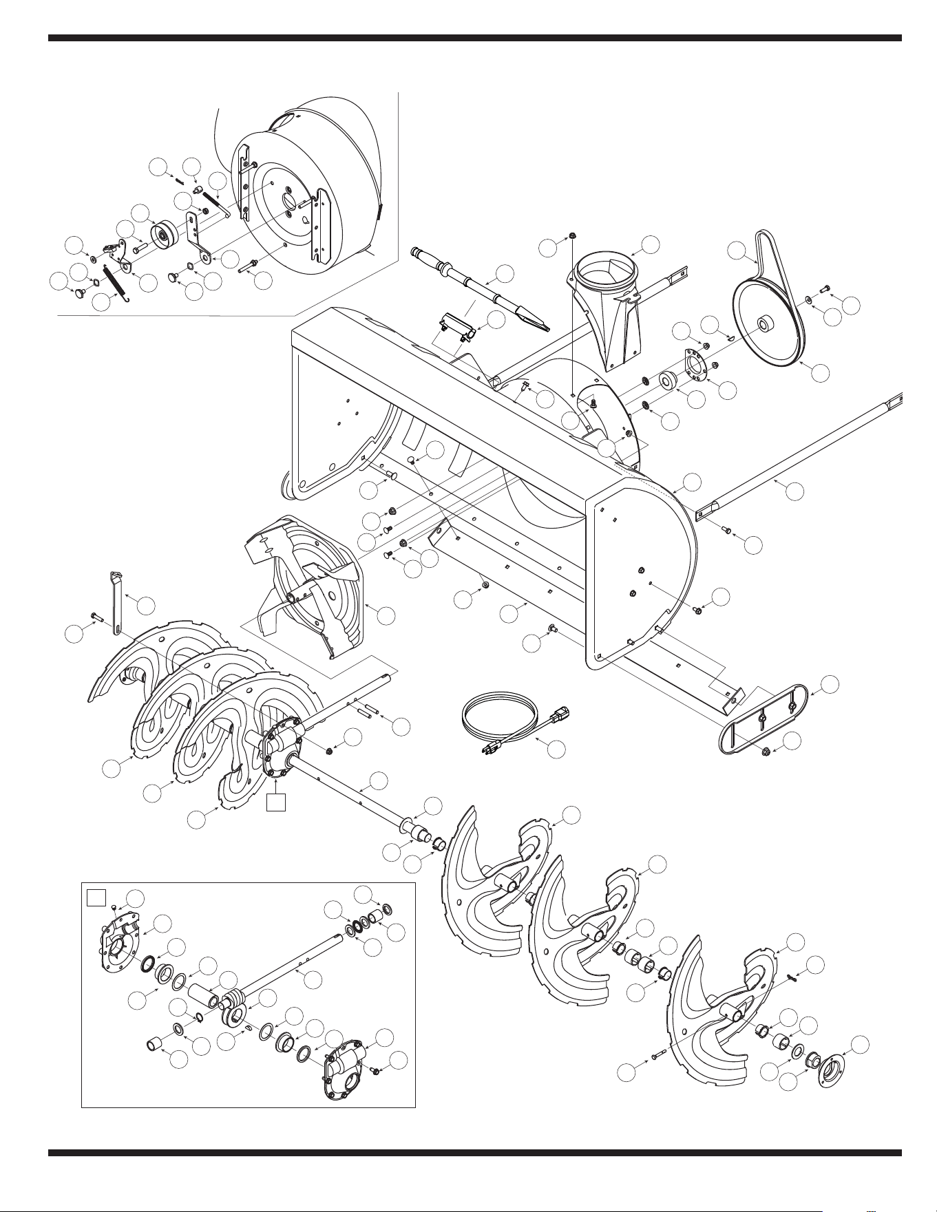
9
Parts List
Ref. No. Part No. Description
1 05244B Housing, Bearing
2 05845C Housing, Double D Bearing
3 618-0257 Gear Box Assembly, Auger
4 618-0281A Bracket Assy, Auger Brake
5 684-0090B Impeller, 16”
6 684-04223 Housing, Auger - 45”
7 684-04151 Spiral Assy, LH
8 684-04152 Spiral Assy, RH
9 710-0371 Screw, Hex Cap Lock
10 710-0451 Screw, Carriage, 5/16-18 x .75
11 710-0459A Screw, Hex Cap, 3/8-24 x 1.5
12 710-0528 Screw, Hex Cap, 5/16-18 x 1.25
13 710-04484 Screw, 5/16-18 x .750
14 726-04012 Nut, Push
15 710-3008 Screw, 5/16-18 x .75 GR5
16 710-3168 Screw, Carriage, 3/8-16 x 1.0
17 710-04606 Screw, 5/16-18 x .4300
18 711-0677 Ferrule
19 712-0116 Nut, Hex Lock, 3/8-24
20 712-04063 Nut, Flange Lock, 5/16-18
21 712-04065 Nut, Flange Lock, 3/8-16
22 714-0104 Pin, Internal Cotter
23 714-0126 Key, Hi Pro, 3/16 x 3/4
24 714-0135 Key, Woodruff, 1/4 x 3/4
25 714-04040 Pin, Bowtie Cotter
26 715-0118 Pin, Spirol, 5/16 x 1.75
27 725-0157† Tie, Cable
28 731-1696A Adapter, Chute, 6”
29 731-05163 Spacer, 1.0 x 1.5 x 1.0
30 731-2635 Clip, Mounting
31 731-2643 Tool, Cleanout
32 732-0858 Spring, Extension
33 736-0174 Washer, .625 x .885 x .015
34 736-0242 Washer, .34 x .872 x .06
Ref. No. Part No. Description
35 750-04020 Spacer, 1.004 x 1.375 x .25
36 629-0071 Extension Cord, 110V
37 736-3008 Washer, .344 x .75 x .12
38 736-3046A Washer, 1.01 x 1.86 x .06
39 738-0281 Screw, Shoulder, .625 x .17
40 738-04155 Pin, Shear, .25 x 1.75
41 738-04159 Shaft, Spiral 45”
42 741-0192 Bearing, Flange w/Flats
43 741-04024 Bearing, Self Aligning
44 741-0494 Bushing, Flange, 1.05 x 1.16
45 747-0980A Rod, Auger Idler
46 749-1117 Tube, Support
47 754-0222A Belt, V, 1/2 x 44
48 756-0178 Pulley, Flat Idler, 2.75 OD
49 756-0243 Pulley, Auger Drive, 10.0
50 784-0385B Bracket, Auger Idler
51 790-00264 Bracket, Gear Box Support
52 790-00280 Plate, Shave 45”
53 784-5697 Shoe, Skid
54 721-0146 Oil Seal
55 618-0246 Hsg Assy Auger, RH (Inc. 54 & 59)
56 618-0247 Hsg Assy Auger, LH (Inc. 54 & 59)
57 710-1260A Screw LD, 5/16-18 x .750
58 711-1133 Shaft, Drive, Auger
59 741-0670 Flange Bearing
60 716-0111 Ext, Ret, Ring
61 717-1425 Gear, Worm, LH
62 721-0145 Seal, Oil
63 736-0266 Washer, Flat, 1.52 ID x 2.0 OD
64 736-0291 Washer, Flat, .88 ID x .38 OD
65 738-0275 Shaft, Gear, Worm
66 741-0184 Brg, Thrust
67 741-0217 Sleeve
68 721-0325 Plug
To order replacement
parts, call
1-800-648-6776
or visit
www.troybilt.com
† Not Shown
26
Storm 13045
A
A
53
50
6
42
25
30
17
52
57
56
49
63
44
43
69
58
21
5
26
33
38
20
19
34
3
19
32
21
2
39
7
36
14
72
41
19
19
35
1
75
76
9
22
29
31
19
68
47
60
61
2
64
65
17
4
59
51
28
45
57
40
48
31
62
52
66
67
24
47
37
70
15
16
10
18
47
68
53
54
52
16
55
46
71
8
9
27
23
28
11
28
43
32
73
74
52
12
13

27
9
Parts List
Ref. No. Part No. Description
1 725-1672 Light Housing
2 646-0012 Cable Assembly, Auger/Drive
3 684-0053B Crank, Chute, 26.0
4 705-5218 Handle, Engage, RH
5 705-5219 Handle, Engage, LH
6 705-5266 Bracket, Chute Crank
7 710-0458 Screw, Carr., 5/16-18 x 1.75
8 710-0572 Screw, Carr., 5/16-18 x 2.5
9 710-1003 Screw, #10-16 x .625
10 710-1625 Screw, #10-24 x 1.75
11 710-1878 Screw, Hex, 3/8-16 x 1,75
12 710-1879 Screw, Hex, 3/8-16 x .88
13 710-3015 Screw, Hex, 1/4-20 x .75
14 711-0677 Ferrule, 5/16-18 x .312 Dia
15 784-5679 Bracket, Handle Support - LH
16 712-04064 Nut, Hex Flange, 1/4-20
17 712-3010 Nut, Hex, 5/16-18 GR5
18 714-0101 Pin, Internal Cotter
19 714-0104 Pin, Internal Cotter
20 720-0201A Knob, Crank
21 720-04039 Knob, Shift
22 720-04072 Knob, Star, 5/16-18
23 725-0157 Tie, Cable
24 784-5682 Bracket, Handle Support - RH
25 784-5681 Bracket, Handle Support - LH
26 726-0100 Cap, Push, 3/8
27 731-04069 Panel, Handle, Style 9
777I22553 Graphic, Auger/Chute
777I22554 Graphic, Chute Tilt
777I22556 Graphic, Starting Instructions
28 736-0105 Washer, Bell, .375 x .87 x .063
29 736-0185 Washer, Flat, .375 x .738 x .063
30 736-0242 Washer, Bell, .34 x .872 x .06
31 736-0275 Washer, Flat, .344 x .688 x .065
32 741-0475 Bushing, Plastic, .38 ID
33 746-0950A Cable Assembly, Trigger
34 747-0624 Rod, Chute Crank
35 747-0983A Rod, Lower Shift
36 747-0997 Rod, Upper Shift
37 784-5680 Bracket, Handle Support - RH
Ref. No. Part No. Description
38 749-0989A Handle, Upper LH
39 749-0990A Handle, Upper RH
40 749-0991 Handle, Lower
41 750-0963 Connector, Shift Rod
42 684-0102A Panel, Handle
43 710-0276 Screw, Carriage, 5/16-18 x 1.0
44 710-0458 Screw, Carriage, 5/16-18 x 1.75
45 710-0459A Screw, Hex, 3/8-24 x 1.5
46 710-0597 Screw, Hex, 1/4-20 x 1.0
47 710-0599 Screw, Hx, 1/4-20 x .5
48 710-0805 Screw, Hex, 5/16-18 x 1.5
49 710-0895 Screw, Hx,1/4-15 x .75
50 711-0653 Pin, Clevis, .312 x 1.0
51 712-0116 Nut, Insert, 3/8-24
52 712-04063 Nut, Flange Lock, 5/16-18
53 714-0507 Pin, Cotter, 3/32 x .75
54 731-0846C Chute, Upper, 6.0
777S32280 Graphic, Danger
55 731-0851A Flange Keeper, Chute
56 731-0903D Chute, Lower
57 731-1313C Cable Guide, Chute Tilt
58 732-0145 Spring, Compression
59 732-0193 Spring, Compression
60 732-0746 Spring, Torsion
61 735-0199A Bumper, Rubber
62 784-5619B Handle, Shift
63 736-0231 Washer, Flat, .344 x 1.125 x .12
64 736-0119 Washer, Lock, 5/16
65 736-0509 Washer, Flat, .35 x .72 x .134
66 746-0902 Cable, Chute Control, 66”
67 746-0903 Cable, Chute Control w/Clip
68 747-0877 Rod, Cam
69 748-0362 Cam, Handle Lock
70 748-0363 Pawl, Handle Lock
71 784-5594 Bracket, Cable
72 784-5604A Handle, Chute Tilt
73 784-5123 Bracket, Chute Crank
74 736-0159 Washer, Flat, .349 x .879 x .063
75 747-1136 Headlight Retainer
76 725-1658 Halogen Lamp
77† 629-04010A Light Harness
To order replacement
parts, call
1-800-648-6776
or visit
www.troybilt.com
† Not Shown
28
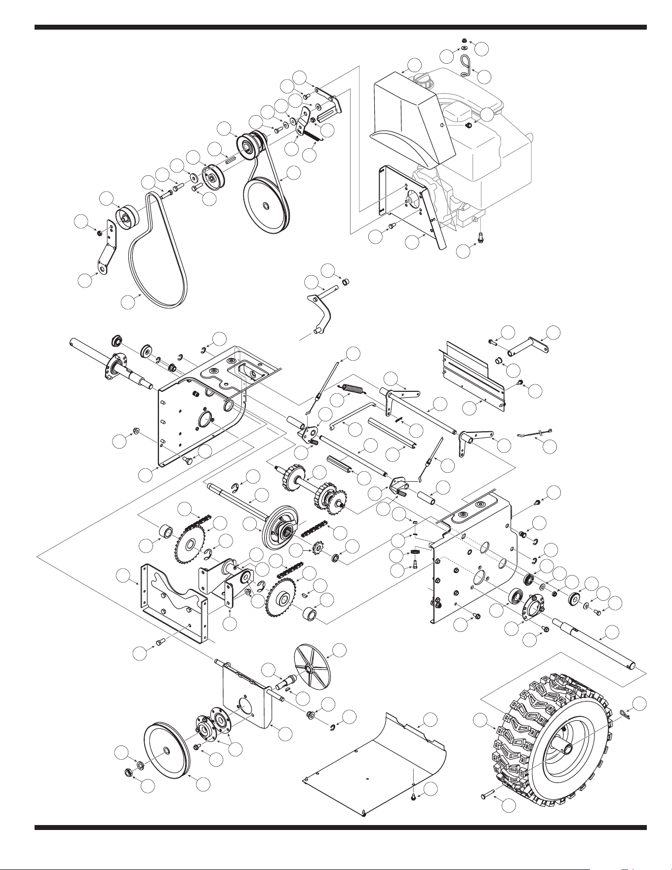
Storm 13045
11
62
9
21
A
B
B
A
17
32
38
61
60
50
26
49
13
73
52
72
58
19
31
59
1
31
35
20
29
12
15
83
79
77
82
92
28
87
26
74
41
36
20
8
53
25
8
56
70
51
27
67
23
2
42
54
38
4
43
43
25
71
24
86
80
18
66
3
63
40
38
69
48
31
10
63
6
93
88
64
17
62
7
37
39
33
65
78
16
57
30
45
55
47
76
61
75
26
14
79
91
85
22
78
89
46
84
44
81
49
90
34
34
5
68
17

29
9
Parts List
Ref. No. Part No. Description
1 05244B Housing, Bearing
2 618-0279 Dogg, Steering Drive, LH
3 618-0280 Dogg, Steering Drive, RH
4 618-0282E Shaft Assembly, Steering
5 618-04178 Assembly, Friction Wheel
718-04034 Wheel, Friction, Bonded
710-0896 Screw, Hex Wash
6 684-0118A Bracket, Auger Actuator
7 684-0119A Bracket, Drive Actuator
8 684-04235 Sprocket, 32T
9 684-0161 Arm, Shift
10 684-04212 Brkt, Friction Drive Suprt.
11 684-04103 Rod Assembly, Shift
12 784-0385B Brkt., Idler, Auger
13 710-0538 Screw, Hex Cap Lock,
14 756-0178 Idler, Flat, 2.75 OD
15 754-0222A V-Belt, 1/2 x 44.0
16 750-04718 Spcr., .51 ID x 3.66 Lg.
17 710-1652 Screw, Hex Wash.
18 750-04717 Spcr., .51 ID x 7.895 Lg.
19 710-3001 Screw, Hex Cap, 3/8-16
20 750-04703 Spcr., 1.0 ID x 1.50 OD
21 710-0788 Screw, Hex, 1/4-20 x 1.00
22 710-0459A Screw, 3/8-24 x 1.50
23 711-04279 Shaft, Hex Drive
24 711-04605 Shaft, Actuator
25 716-04048 Ring, Retainer
26 712-0116 Nut, Hex Insert Jam Lock
27 712-0138 Nut, Hex, 1/4-28 GR5
28 784-5726 Bracket, Idler, Drive
29 712-04065 Nut, Hx Flnge Insert Lk
30 712-0413 Nut, Hx Insert Jam Lk
31 710-04484 TT Screw, 5/16-18 x .750
32 712-0717 Nut, Insert 3/8-16
33 713-0284 Chain, Endless, #41 x 36L
34 713-0286 Chain, #420 x 40L
35 713-04015 Sprocket, #41 x 10T
36 714-0135 Key, Woodruff
37 714-0104 Pin, Internal Cotter
38 716-0104 E-Ring
39 714-0388 Key, Hi-Pro, 3/16 x 5/8
40 716-0136 Ring, Retaining
Ref. No. Part No. Description
41 717-0302 Plate, Drive
42 732-0121 Spring, Extension
43 732-0209 Spring, Extension
44 756-0241B Pulley, Dbl, 3.25 OD
45 736-0158 Washer, Lock, 5/8
46 756-0240 Pulley, Flat Idler, 3.0 OD
47 634-0225 Wheel Assembly - LH
634-0226 Wheel Assembly - RH
734-2031 Tire
734-0255 Valve
741-0246A Bearing
48 711-04615 Pin, Clevis
49 736-0242 Wsh, Bell., .34 x .872 x .06
50 736-0300 Wash, .406 x .875 x .059
51 736-0329 Washer, Lock, 1/4
52 714-0149B Pin, Internal Cotter
53 737-3000 Fitting, Lube, 3/16 Drive
54 738-0143 Screw, Shldr., .498 x .34
55 738-0279 Spindle, Drive Plate
56 738-0924A Screw, Hex Shldr., 1/4-28
57 741-0163A Ass’y, Bearing/Housing
58 741-04108 Bearing, Hex Flange
59 741-04025 Bearing, Self Aligning
60 741-04076 Bearing, Ball
61 741-0563 Bearing, Ball
62 741-0748 Bush, Flg, .5 ID x .627 OD
63 746-0949A Cable, Steering
64 746-0951 Cable, Auger Idler
65 747-0973 Rod, Drive Clutch
66 750-0903B Spcr., .514 x .632 x 2.44
67 750-0997 Spacer, .675 x 1.0 x .23
68 750-1302B Spcr, .6725 x 1.125 x 2.48
69 756-0344 Pulley, Drive
70 756-0625 Roller, Cable
71 790-00257 Cover, Upper Frame
72 790-00259 Cover, Lower Frame
73 711-04606 Axle, Wheel
74 790-00255 Frame, Transmission
75 784-0406A Bracket, Frame Support
76 784-0407 Bracket, Axle Support
77 790-00254 Bracket, Belt Cover
78 710-0191 Screw, 3/8-14 x 1.25 GR8
Continued on following page
To order replacement
parts, call
1-800-648-6776
or visit
www.troybilt.com

30
9
Parts List
Ref. No. Part No. Description
79 710-0237 Screw, 5/16-24 x .625
80 710-0607 Screw, Hx Wash Hd Tapp
81 710-1245B Screw, Hx Cap 5/16-24
82 710-0654A Screw, 3/8-16 x 1.00
83 736-0173 Wsh, Flat, .28 x .74 x .063
84 714-0118 Key, Square, 1/4 x 1.5
85 790-00167A Brkt., Belt, Keeper
86 731-2531 Cover, Belt
87 732-0303 Spring, Extension
88 732-0705 Guide, Chute Cable
89 736-0247 Washer, Flat, .406 x 1.25
90 748-0234 Spacer, Shoulder
91 736-0159 Washer, Flat, .349 x .879
92 754-0131 V-Belt, 3/8 x 35.5
93 712-04064 Nut, Flg Lk, 1/4-20
Continued from previous page
To order replacement
parts, call
1-800-648-6776
or visit
www.troybilt.com

31
NOTES

The limited warranty set forth below is given by Troy-Bilt LLC with respect
to new merchandise purchased and used in the United States and/or its
territories and possessions, and by MTD Products Limited with respect to
new merchandise purchased and used in Canada and/or its territories and
possessions (either entity respectively, “Troy-Bilt”).
“Troy-Bilt” warrants this product (excluding its normal wear parts as
described below) against defects in material and workmanship for a
period of two (2) years commencing on the date of original purchase and
will, at its option, repair or replace, free of charge, any part found to be
defective in materials or workmanship. This limited warranty shall only
apply if this product has been operated and maintained in accordance
with the Operator’s Manual furnished with the product, and has not been
subject to misuse, abuse, commercial use, neglect, accident, improper
maintenance, alteration, vandalism, theft, fire, water, or damage because
of other peril or natural disaster. Damage resulting from the installation or
use of any part, accessory or attachment not approved by Troy-Bilt for use
with the product(s) covered by this manual will void your warranty as to any
resulting damage.
Normal wear parts are warranted to be free from defects in material and
workmanship for a period of thirty (30) days from the date of purchase.
Normal wear parts include, but are not limited to items such as: batteries,
belts, blades, blade adapters, grass bags, rider deck wheels, seats, snow
thrower skid shoes, friction wheels, shave plates, auger spiral rubber and
tires.
HOW TO OBTAIN SERVICE: Warranty service is available, WITH PROOF
OF PURCHASE, through your local authorized service dealer. To locate
the dealer in your area:
In the U.S.A.
Check your Yellow Pages, or contact Troy-Bilt LLC at P.O. Box 361131,
Cleveland, Ohio 44136-0019, or call 1-866-840-6483 or 1-330-558-7220,
or log on to our Web site at www.troybilt.com.
In Canada
Contact MTD Products Limited, Kitchener, ON N2G 4J1, or call 1-800-668-
1238 or log on to our Web site at www.mtdcanada.com.
This limited warranty does not provide coverage in the following cases:
a. The engine or component parts thereof. These items may
carry a separate manufacturer’s warranty. Refer to applicable
manufacturer’s warranty for terms and conditions.
b. Log splitter pumps, valves, and cylinders have a separate one-
year warranty.
c. Routine maintenance items such as lubricants, filters, blade
sharpening, tune-ups, brake adjustments, clutch adjustments,
deck adjustments, and normal deterioration of the exterior finish
due to use or exposure.
d. Service completed by someone other than an authorized service
dealer.
e. Troy-Bilt does not extend any warranty for products sold or
exported outside of the United States and/or Canada, and
their respective possessions and territories, except those sold
through Troy-Bilt’s authorized channels of export distribution.
f. Replacement parts that are not genuine Troy-Bilt parts.
g. Transportation charges and service calls.
h. If Products are used commercially. (Troy-Bilt may separately
offer Limited Commercial Warranties on certain select products.
Ask your dealer or retailer for details or contact Troy-Bilt Service
for more information).
No implied warranty, including any implied warranty of merchant-
ability of fitness for a particular purpose, applies after the applicable
period of express written warranty above as to the parts as identi-
fied. No other express warranty, whether written or oral, except as
mentioned above, given by any person or entity, including a dealer or
retailer, with respect to any product, shall bind Troy-Bilt. During the
period of the warranty, the exclusive remedy is repair or replacement
of the product as set forth above.
The provisions as set forth in this warranty provide the sole and
exclusive remedy arising from the sale. Troy-Bilt shall not be liable
for incidental or consequential loss or damage including, without
limitation, expenses incurred for substitute or replacement lawn care
services or for rental expenses to temporarily replace a warranted
product.
Some states do not allow the exclusion or limitation of incidental or
consequential damages, or limitations on how long an implied warranty
lasts, so the above exclusions or limitations may not apply to you.
In no event shall recovery of any kind be greater than the amount of the
purchase price of the product sold. Alteration of safety features of the
product shall void this warranty. You assume the risk and liability for
loss, damage, or injury to you and your property and/or to others and their
property arising out of the misuse or inability to use the product.
This limited warranty shall not extend to anyone other than the original
purchaser or to the person for whom it was purchased as a gift.
HOW STATE LAW RELATES TO THIS WARRANTY: This limited war-
ranty gives you specific legal rights, and you may also have other rights
which vary from state to state.
IMPORTANT: Owner must present Original Proof of Purchase to obtain
warranty coverage.
Troy-Bilt LLC, P.O. BOX 361131 CLEVELAND, OHIO 44136-0019; Phone: 1-866-840-6483, 1-330-558-7220
MTD Canada Limited - KITCHENER, ON N2G 4J1; Phone 1-800-668-1238
MANUFACTURER’S LIMITED WARRANTY FOR