Loading ...
Loading ...
Loading ...

RE3 UHF Wireless RE3-RX receiver | en 21
Electro-Voice
User Manual
02-2023 | 05 | F.01U.362.808
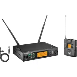
ID Item Description, usage, and notes
5 SET button The most commonly used menu navigation button, it is a multi-
purpose action button which functions as an enter key, a menu
advance key, an item select key, and a save or store key.
6 Power button Turns the receiver on or off. Press in to turn the receiver on. Press in
again to turn the receiver off.
7 ▼ down button This is a dual-purpose menu navigation button.
As a menu scroll button, press the scroll downward through the main
menu items.
As an editable parameter value adjuster, press the ▼ button to
decrease the displayed value of the current parameter, or the next
state condition value below the displayed state value.
Pressing while displaying the main operating menu decreases the
audio output level.
8 ▲ up button This is a dual-purpose menu navigation button.
As a menu scroll button, press the scroll upward through the main
menu items.
As an editable parameter value adjuster, press the ▲ button to
increase the displayed value of the current parameter, or the next
state condition value above the displayed state value.
Pressing while displaying the main operating menu increases the
audio output level.
9 LCD display Backlit LCD displays all operating information and menus.
10 AF meter AF (audio frequency) meter is a seven-segment LED containing five
green segments, one yellow segment, and one red segment. It
displays the audio signal strength received from the transmitter.
Fewer lit segments indicate a weaker audio signal compared to more
lit segments indicating a stronger audio signal. The red segment
warns of a potential audio clip.
11 RF meter RF (radio frequency) meter is a seven-segment LED indicator. It
displays the RF signal strength received from the transmitter.
Fewer lit segments indicate a weaker radio signal compared to more
lit segments indicating a stronger radio signal.
12 Antenna A jack BNC RF jack to attach either a supplied half-wave whip antenna, or
antenna extension coax cable connected to a front-mounted or
remote extension antenna. This jack supplies 12 volts DC booster
feed to power in-line RF amplifiers or active antennas when antenna
power is set to on (factory default). The RE3 diversity receiver
requires connecting antennas to both antenna jacks.
13 AF output jack
(unbalanced
audio)
¼" audio output jack (1/4" TS). Using a standard unbalanced
instrument cable, connect this to the balanced microphone input
jack (mic level) on a mixer, powered loudspeaker, or signal
processor.
Loading ...
Loading ...
Loading ...
