
2
TABLE OF CONTENTS
1. Introduction ...............................................................................................................................................................5
1.1. Product Compliance .....................................................................................................................................................................5
1.2 Safety Informations .......................................................................................................................................................................5
1.3 Product Overview ..........................................................................................................................................................................5
2. Montage.....................................................................................................................................................................6
2.1 Package Content ............................................................................................................................................................................6
2.2 Proper thermostat location ...........................................................................................................................................................6
2.3 Wiring diagram (SQ610RF Quantum thermostat) ..........................................................................................................................6
3. About ZigBee network ................................................................................................................................................7
3.1 ZigBee network - creation and work ..............................................................................................................................................7
3.2 Compatibility with SALUS devices (ONLINE AND OFFLINE) .............................................................................................................8
4. Before you start (rst power up) ..................................................................................................................................9
4.1 LCD icon description ......................................................................................................................................................................9
4.2 Button Description ........................................................................................................................................................................9
4.3 Li-on battery charging ................................................................................................................................................................10
4.4 First power up sequence, language choice and preparing to the pair process ..............................................................................10
5. Installation by SALUS Smart Home application (ONLINE MODE) .....................................................................................11
5.1 General Informations about SALUS Smart Home application ......................................................................................................11
5.2 Pairing with underoor heating wiring centre (KL08RF/Control Box) ..........................................................................................12
5.3 Pairing with wireless TRV radiator head ......................................................................................................................................15
5.4 Pairing with Smart Plug SPE600 ..................................................................................................................................................17
5.5 Pairing with Smart Relay SR600 ..................................................................................................................................................19
5.6 Pairing with RX10RF receiver .......................................................................................................................................................21
6. OPERATING in ONLINE MODE (by app) ..........................................................................................................................23
6.1 General Informations ..................................................................................................................................................................23
6.2 App icons description ..................................................................................................................................................................23
6.3 Change thermostat name (pencil tool) ........................................................................................................................................24
6.4 Setpoint temperature change .....................................................................................................................................................25
6.5 Heat/Cool mode change (KL08RF connection) .............................................................................................................................26
6.6 Thermostat modes ......................................................................................................................................................................27
6.6.1 Schedule Mode ..........................................................................................................................................................27
6.6.2 Temporary override mode ..........................................................................................................................................31
6.6.3 Manual mode .............................................................................................................................................................31
6.6.4 Standby Mode ............................................................................................................................................................32
6.7 Key Lock Function ........................................................................................................................................................................33
6.8 Compatibility with window/door sensor OS600 / SW600 ...........................................................................................................34
6.9 Compatibility with Smart Plug SPE600 ........................................................................................................................................35
6.10 Compatibility with Smart Relay SR600 ......................................................................................................................................36
6.11 Identication mode ...................................................................................................................................................................37
6.12 Pinning/unpinning thermostat to/from application dashboard ................................................................................................38
6.13 User settings (basic settings) .....................................................................................................................................................39
6.14 Admin Settings (Installer parameters) ......................................................................................................................................40
6.15 OneTouch rules (add/edit) ........................................................................................................................................................41
6.16 Error codes (exclamation mark in app) ......................................................................................................................................45
6.17 Wireless signal strength test .....................................................................................................................................................46
6.18 Factory reset (removing thermostat from the app and ZigBee network) ...................................................................................47

3
7. Installation in OFFLINE MODE without SALUS SmartHome application ..........................................................................49
7.1 General informations .................................................................................................................................................................49
7.2 Pairing with underoor heating wiring centre (KL08RF/Control Box) ..........................................................................................50
7.3 Pairing with wireless TRV radiator head ......................................................................................................................................51
7.4 Pairing with RX10RF receiver .......................................................................................................................................................52
8. OPERATING in OFFLINE MODE ......................................................................................................................................53
8.1 Setpoint temperature change (manual mode) ............................................................................................................................53
8.2 Schedule mode ............................................................................................................................................................................54
8.3 Temporary override mode ...........................................................................................................................................................55
8.4 Standby mode .............................................................................................................................................................................55
8.5 Key lock function .........................................................................................................................................................................55
8.6 User settings (basic settings) .......................................................................................................................................................56
8.6.1 Time/Date ..................................................................................................................................................................56
8.6.2 Holiday mode .............................................................................................................................................................57
8.6.3 Thermostat calibration ...............................................................................................................................................58
8.6.4 Display humidity ........................................................................................................................................................58
8.6.5 Display oor temp ......................................................................................................................................................59
8.6.6 Standby temp setpoint ..............................................................................................................................................59
8.6.7 Heat/cool selection ....................................................................................................................................................60
8.6.8 Reset user settings .....................................................................................................................................................60
9. Admin settings (installer parameters) ........................................................................................................................61
10. Factory Reset ..........................................................................................................................................................65
11. Error codes (error codes description with possible solutions) ......................................................................................65
12. Cleaning and Maintenance ......................................................................................................................................68
13. Technical Informations ............................................................................................................................................68
14. Warranty ................................................................................................................................................................68

4
5
This product complies with the essential requirements and other relevant provisions of Directives 2014/53/EU and 2011/65/EU. The full text of the EU
Declaration of Conformity is available at the following internet address: www.saluslegal.com.
Use in accordance to national and EU regulations. Use the device as intended, keeping it in dry condition. Product for indoor use only. Installation must
be carried out by a qualied person in accordance to national and EU regulations. Disconnect your equipment before cleaning it with a dry cloth.
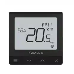
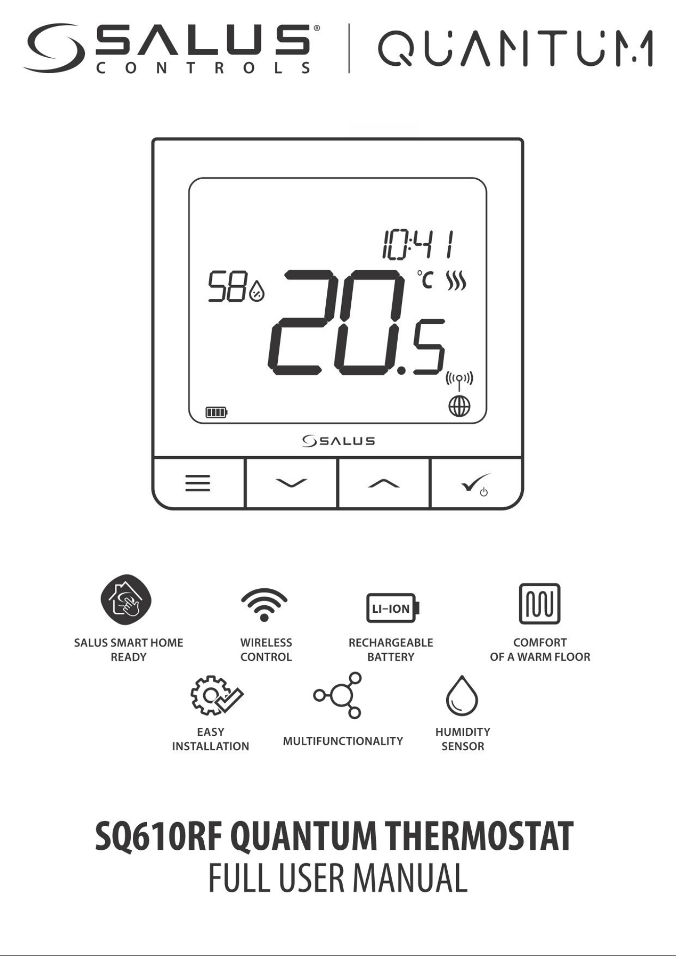
The SQ610RF Quantum is a ZigBee temperature controller for wireless control of iT600 series devices, such as the KL08RF wiring centre, mini TRV head,
RX10RF boiler control module. In order to control SQ610RF over the Internet or via the SALUS Smart Home mobile app (ONLINE mode), it must be
installed together with the UGE600 Internet gateway (sold separately). From the application level, it is possible to pair SQ610RF with other system ele-
ments, e.g. Smart Plug SPE600, Smart Relay SR600 or window/ door sensor OS600/SW600. SQ610RF can be used locally without an Internet connection
(OFFLINE mode), however, it’s communication with other devices must be done using the CO10RF coordinator (sold separately).
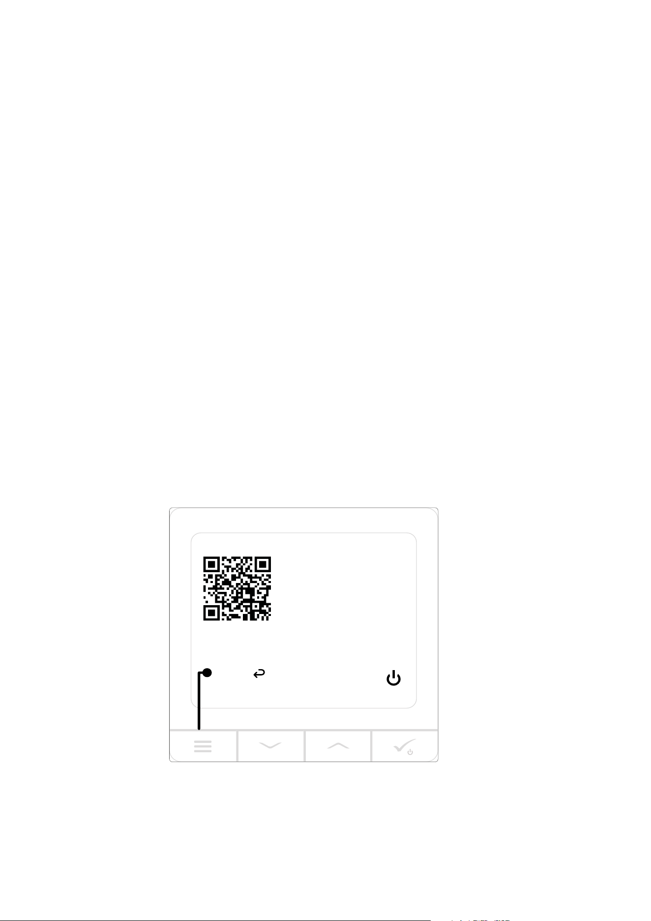
SQ610RF Quantum thermostat (front view)
MENU / Press for 3 sec
to POWER UP
For more information
scan this code or visit:
www.salus-controls.com
3 sec
1. Introduction
1.1. Product Compliance
1.2 Safety Informations
1.3 Product Overview
6
2. Montage
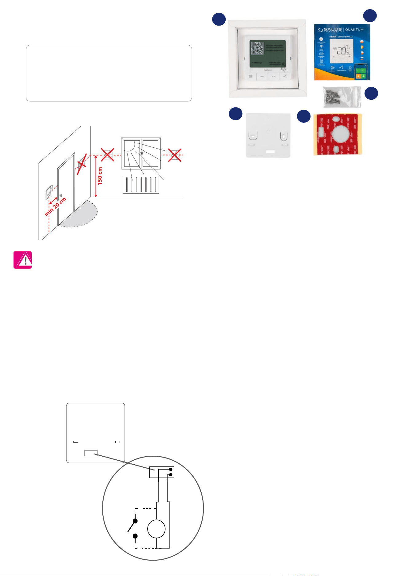
2.1 Package Content
1) SQ610RF Quantum thermostat
2) Wall mounting plate
3) Self-adhesive mounting tape
4) Mounting screws
5) Manual instruction
2.2 Proper thermostat location
Please note:
Wall Mounting
2.3 Wiring diagram (SQ610RF Quantum thermostat)
S1, S2 terminals:
- air or oor temperature sensor
- external volt-free contact to connect any
ON/OFF switch or occupancy sensor (hotel card)
Symbols explanation:
S – volt-free contact
T – temperature sensor eg. FS300
S1
S2
T
S
Mounting: to mount thermostat you can use accesories included with the set (mounting screws or self-adhesive tape). Remove back cover to mount
the plate to the wall. After this just attach thermostat to the plate (it has built-in magnet).
The ideal position to thermostat mounting is about 1,5m under oor level far from heating or cooling sources. Thermostat can’t be
exposed to sunlight or any extreme conditions like for example draft.
Because of re and explosion risk there is not allowed to use thermostat in atmosphere of explosive gases and ammable liquids (eg. coal dust). In case
if any of listed dangers occur you have to use additional protection measures – anti-dust and explosive gases (tight cover) or prevent their formation.
Furthermore, thermostat can’t be used in condensation of water vapor conditions and be exposed to water action.
1
2
3
4
5
7
3. About ZigBee network
3.1 ZigBee network - creation and work
ZigBee is a wireless network based on IEEE 802.15.4 standard and it’s communication takes place in the 2.4 GHz band. The network is based on a mesh
topology, which allows for a very large range and high reliability. The maximum range of direct communication between two network nodes (devices) is
about 100m in open space.
The devices included in the ZigBee network are divided into three types:
- coordinator - there can only be one such device in each network. It acts as a connection node for all devices;
- router (repeater) - this device is powered by 230VAC, with functionality similar to classic network routers, and it’s task is to forward data packets and
increase the range of the network;
- terminal device - battery powered, sends data to the coordinator (also through the router) to which it is connected. It is usually put to sleep temporarily,
which helps reduce energy consumption.
Built-in security in the ZigBee protocol (ISO-27001 and SSAE16 / ISAE 3402 Type II - SOC 2 certication) ensure high transmission reliability, detection and
removal of transmission errors, as well as connectivity between established priority devices.
Security measures include:
- devices authenticated using a unique key pair;
- encrypted communication between the mobile application and the device;
- data encryption - HTTPS encrypted using TLS, UDP channel with AES-128 encryption;
- layered access control to prevent tampering with one device threatening the entire system.
The ability to work many devices at a short distance from each other was achieved through the use of radio transmission of the spread spectrum signal.
The main advantages of devices working in the ZigBee system are two-way communication and minimization of energy consumption, which in many
cases allows them to be powered from chemical cells (alkaline batteries).
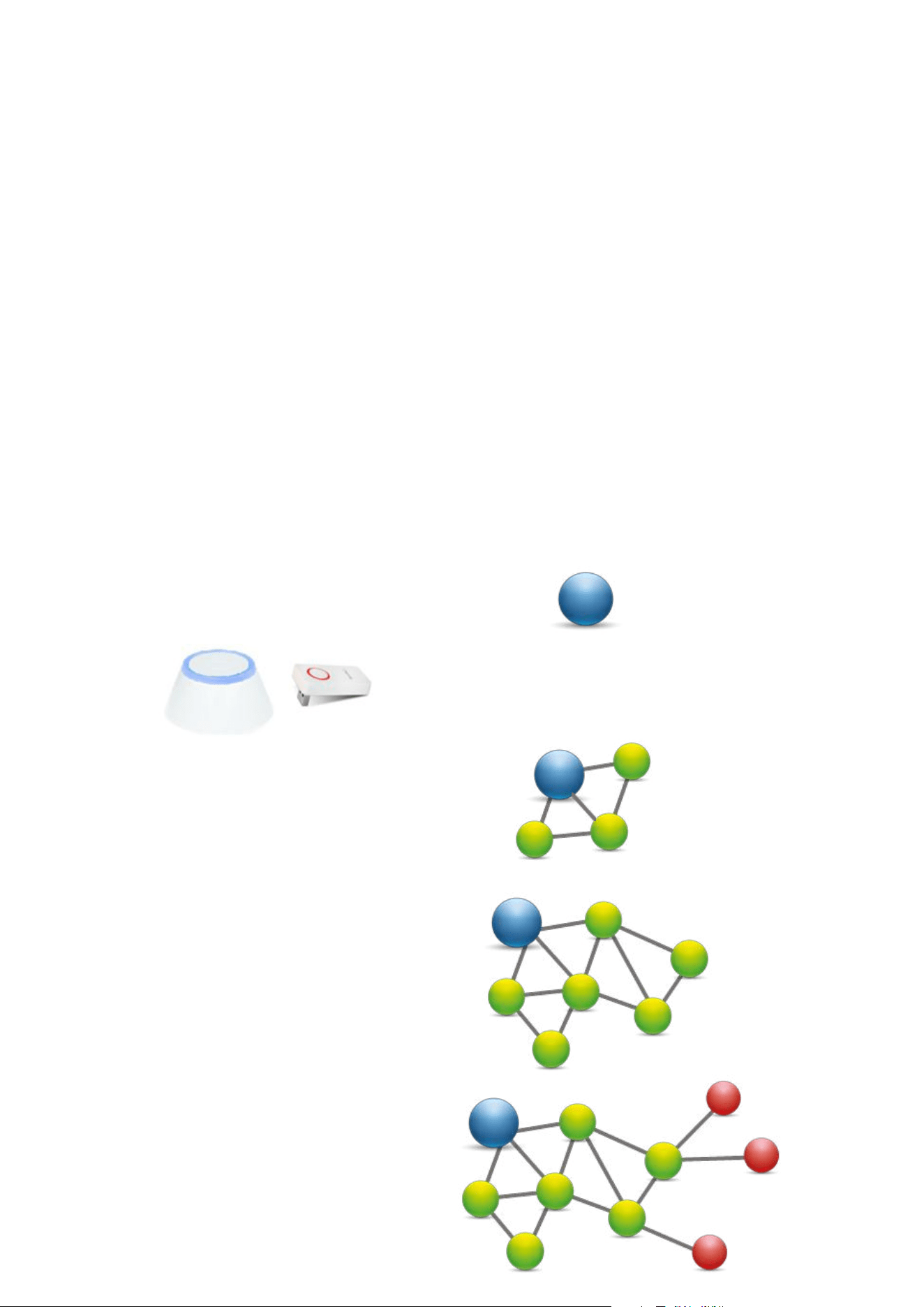
Four simple steps on how to properly create a ZigBee network:
1.
Coordinator Installation - Universal Gateway for
ONLINE and OFFLINE systems with internet application or
CO10RF for only OFFLINE systems without application.
2.
Now - add any device you want powered 230VAC.
Note to locate it as near coordinator as possible.
3.
Now you can increase range of ZigBee network by
adding more devices powered 230 VAC.
4.
To extend your network you can add more battery
devices and accesories.
8
3.2 Compatibility with SALUS devices (ONLINE AND OFFLINE)
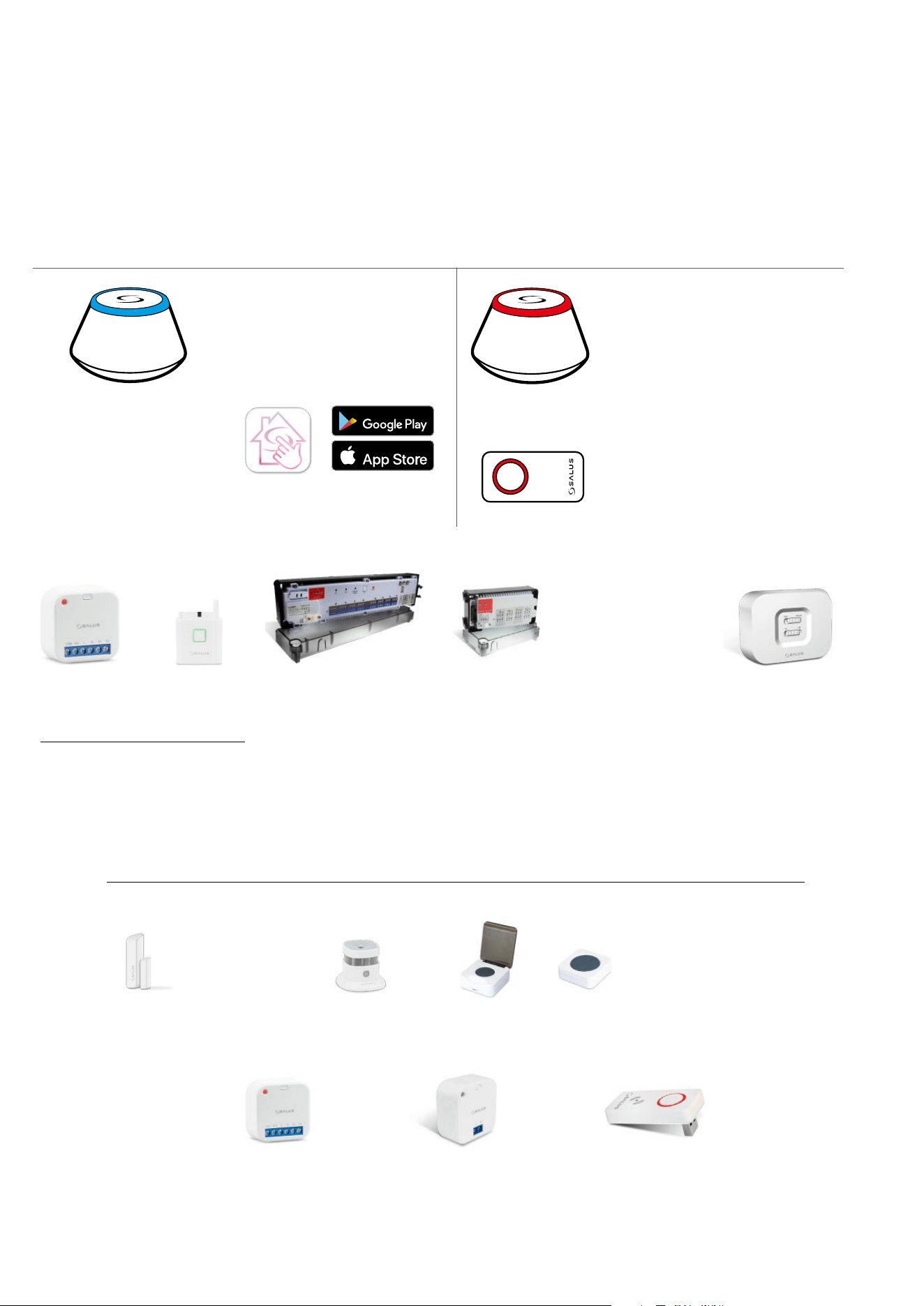
COMPATIBILTY WITH OTHER SALUS CONTROLS DEVICES
Quantum thermostat can work in ONLINE or OFFLINE mode. Quantum thermostat can work in ONLINE or OFFLINE mode.
At rst step you need to decide in which mode your thermostat will work. At rst step you need to decide in which mode your thermostat will work.
ONLINE MODE OFFLINE MODE
Universal Gateway is
CONNECTED TO THE INTERNET
You can congure and use all your
devices in the Smart Home App
Download the Smart Home App
on your iOS or Android device
for remote access to your SALUS
equipment.
SALUS
Smart Home
CO10RF Coordinator - You can use
standard ZigBee network coordinator
to install and use your devices.
Universal Gateway is NOT
CONNECTED TO THE INTERNET
You can use your devices locally
without the Smar tHome App. G ateway
works in this mode as standard ZigBee
coordinator.
Compatibile devices:
KL08RF wireless wiring
centre for 8-zone
underoor heating.
KL04RF extension
TRV
(Thermostatic
Radiator Valve) with
wireless communication.
RX10RF
receiver
SR600
Smart Relay
SPE600
Smart Plug
GET IT ON
Download on the
OR
Other SmartHome devices/accessories
Only with Online Mode
Water leak sensor
WLS600
Double/single OneTouch button
SB600/CSB600
Smoke detector
SD600
Window/door Sensor
SW600 or OS600
RS600
Roller shutter
RE600
ZigBee network signal repeater
(only with UGE600)
RE10RF
ZigBee network signal
repeater
9
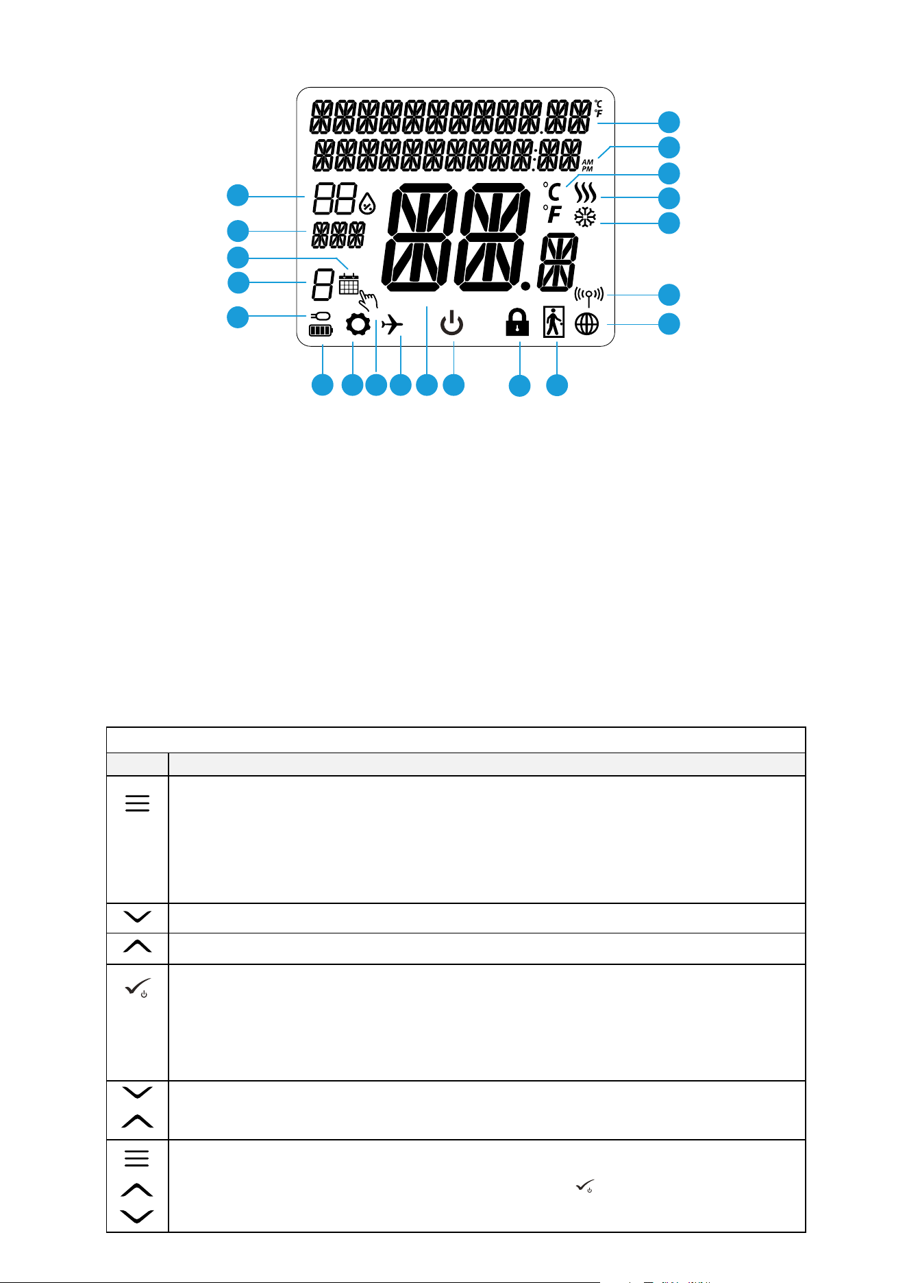
4. Before you start (rst power up)
1. Menu/Settings description + Clock
2. AM/PM
3. Temperature unit
4. Heating indicator (icon is animating when there is
heating demand)
5. Cooling indicator (icon is animating when there is
cooling demand)
6. RF Connection indicator
7. Internet conection indicator
8. Occupancy sensor (hotel card)
9. Key lock function
10. Standby mode icon
11. Current Temperature / Setpoint Temperature
12. Holiday mode
13. Temporary override mode
14. Settings icon
15. Baterry indicator
16. External / Floor temp sensor indicator
17. Schedule program number
18. Schedule mode icon
19. Day indicator/ SET information
20. Humidity Display
2
8
9
10111214
15
20
19
18
17
16
1
3
4
5
6
7
13
+
ON THE MAIN SCREEN: Press and hold the buttons for 6 seconds to activate THE SLEEP MODE. After activation of this mode
thermostat functions are turned o (inactive). To restart the thermostat, press the button for 6 seconds. The thermostat will
return to the previous operating mode.
Button
Function
Button Description
4.2 Button Description
4.1 LCD icon description
+
+
ON THE MAIN SCREEN:
press and hold these buttons together for 3 seconds to LOCK / UNLOCK the thermostat keys.
Unlock – do the same action again).
„Down” Button (Decrease parameter value/moving on the menu in ‘DOWN’ direction)
“Up” Button (Increase parameter value/moving on the menu in ‘UP’ direction)
1) Press and hold for 3 seconds to POWER UP new device
2) “OK / Tick” Button (Conrm parameter value / Go to the next menu / Save settings)
3)
ON THE MAIN SCREEN:
Press and hold for 3 seconds to enter Standby mode
4) ON THE SETTINGS SCREEN: Press and hold for 3 sec to go back to the MAIN SCREEN & SAVE all the changes.
5) During PAIRING process – hold button for 3 seconds to POWER OFF or REBOOT the thermostat.
1) Menu button / Return button.
2)
ON THE MAIN SCREEN:
Press and hold for 3 sec to change the thermostat operating mode
(Schedule mode / Manual mode).
3) ON THE SETTINGS SCREEN: Press and hold for 3 sec to go back without saving the changes.
4) ON THE PAIRING SCREEN (in SYSTEM TYPE Menu): Press and hold for 3 sec to see other pairing options.
10
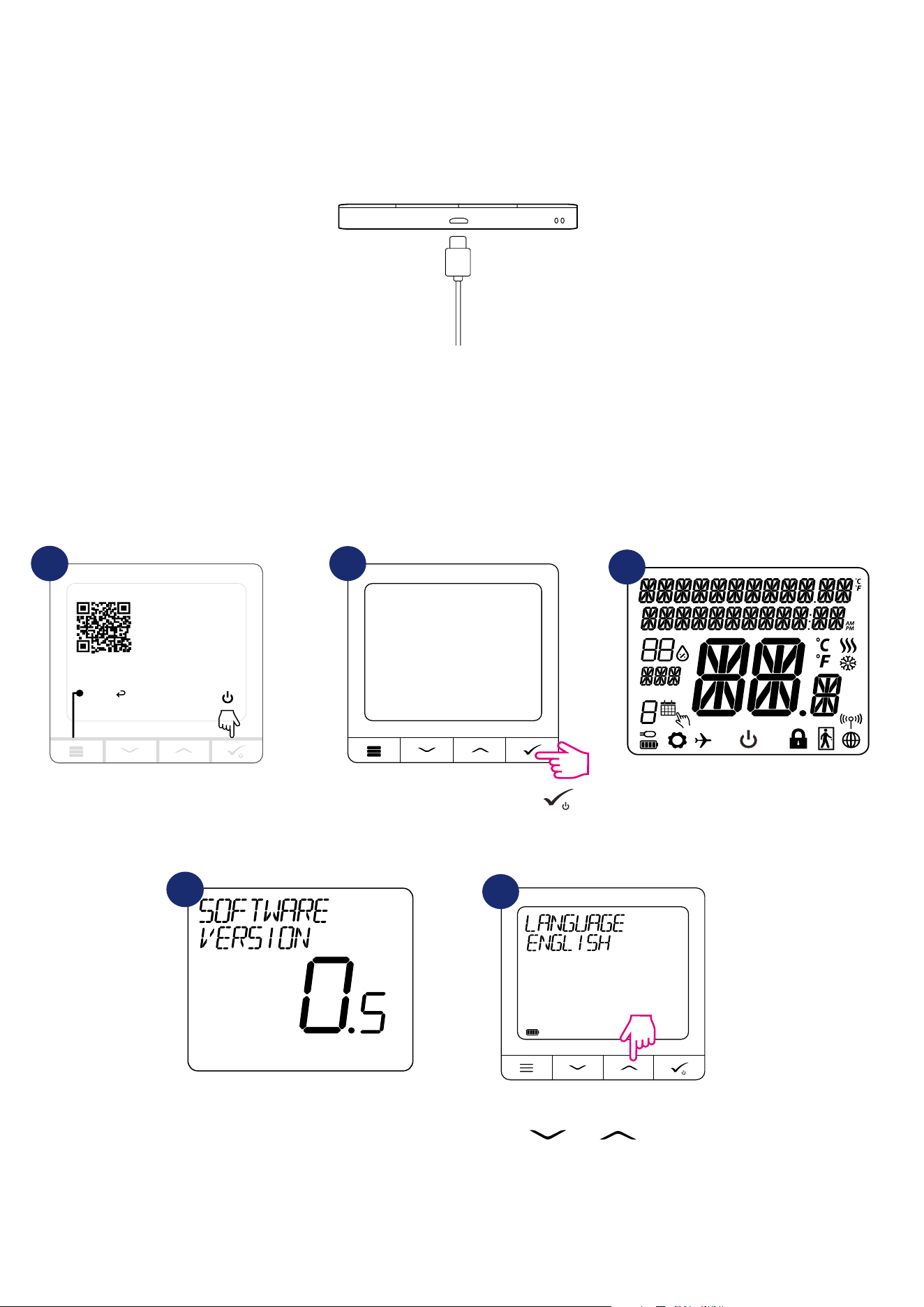
4.3 Li-on battery charging
Charging to full battery level may take up to 24h maximum.
New SQ610RF Quantum thermostat is partially charged, however, we recommend you to fully charge the battery before use.
Connect charger to micro-USB port which is at the bottom of SQ610RF Quantum thermostat to charge the device.
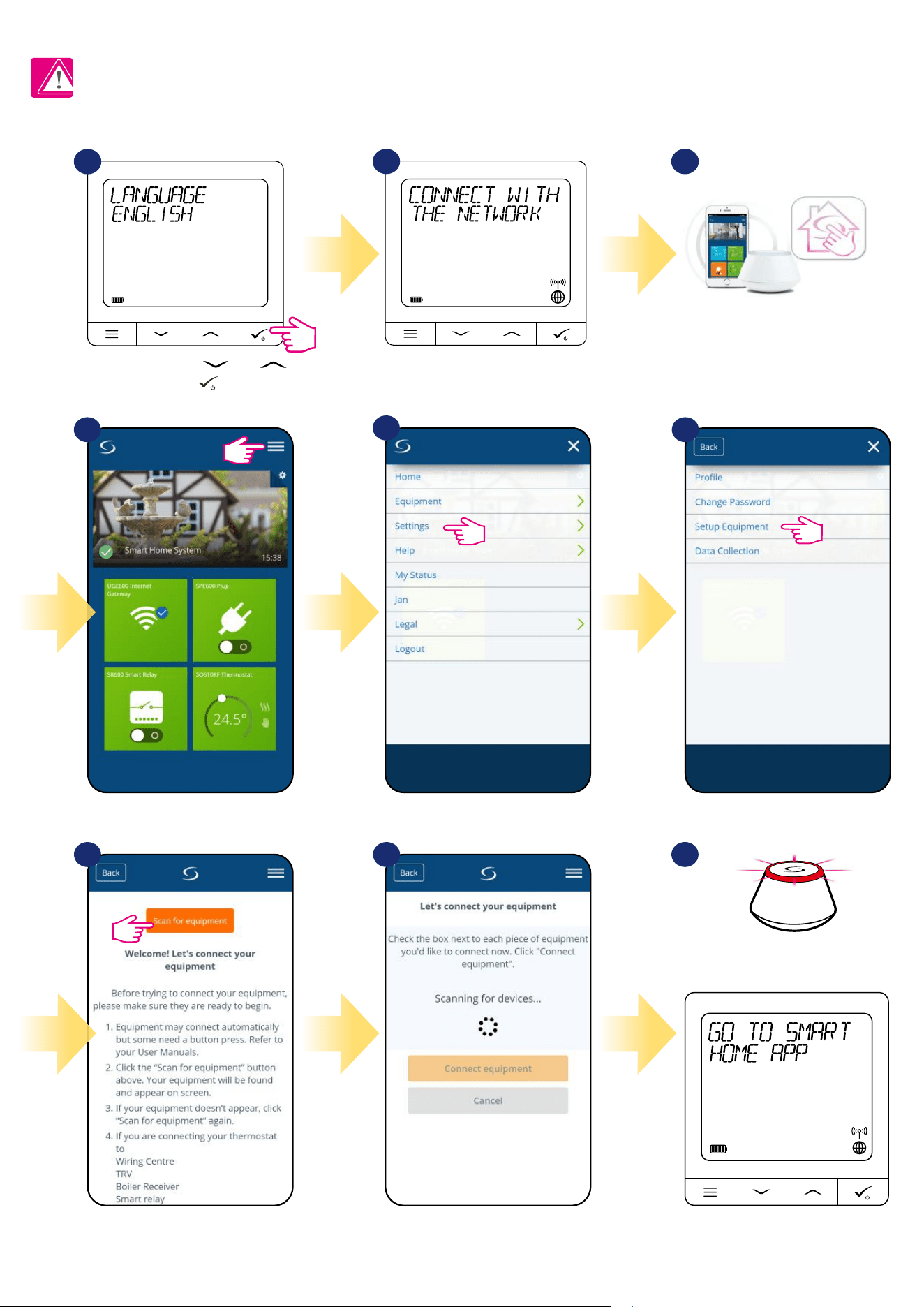
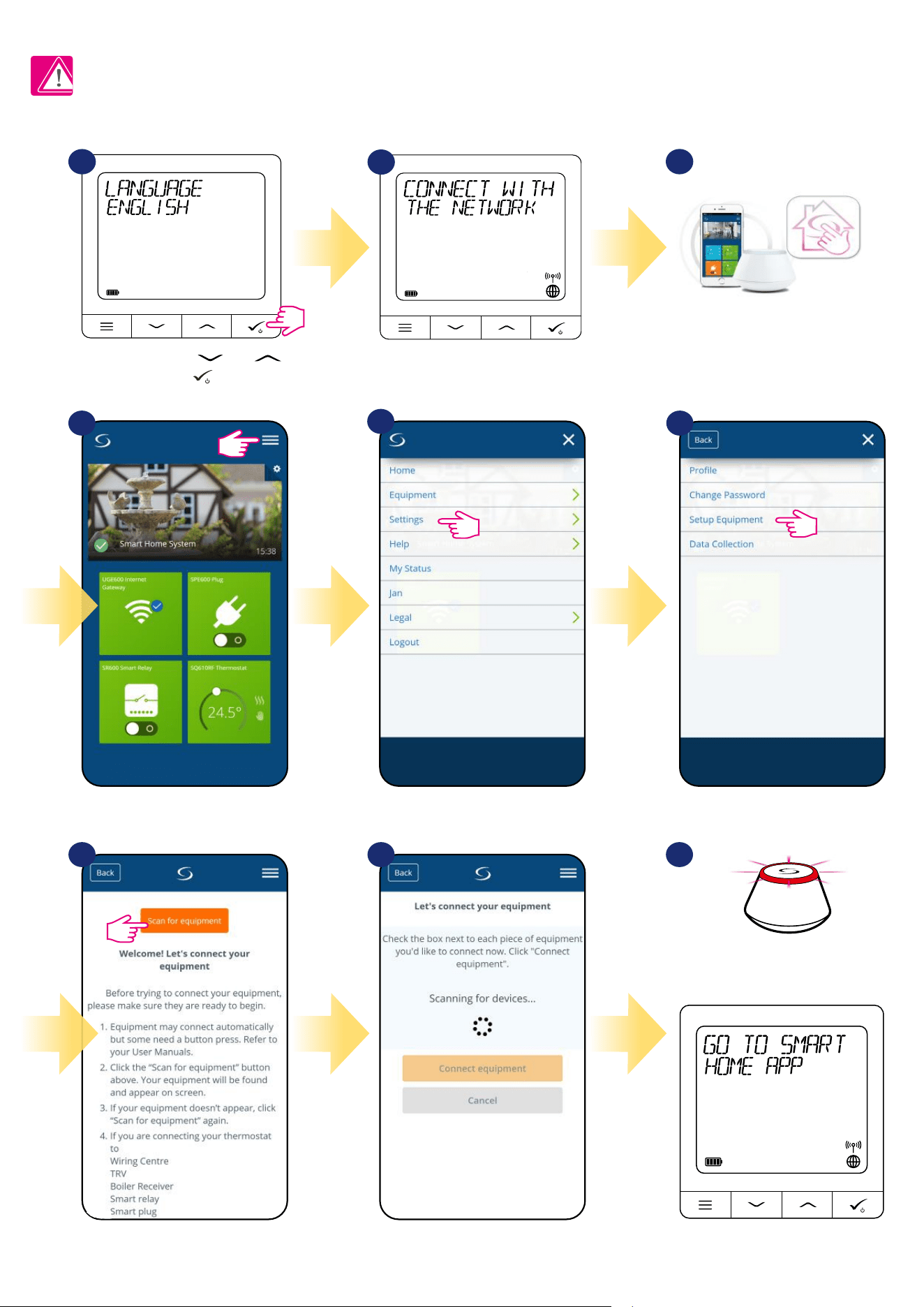
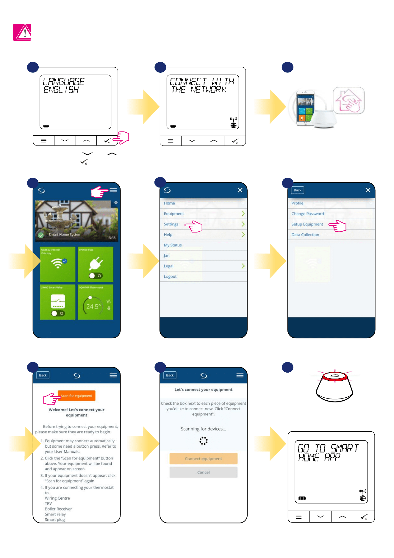
4.4 First power up sequence, language choice and preparing to the pair process
To power on the thermostat hold
button for 3 seconds...
3 sec
Now, choose your language by
„ ” or „ ” buttons.
Conrm your language by tick button.
...display will show all icons...
...then thermostat will display the
software version.
MENU / Press for 3 sec
to POWER UP
For more information
scan this code or visit
:
www.salus-controls.com
3 sec
Remove the protection foil
3
2
1
5
4
11
3
2
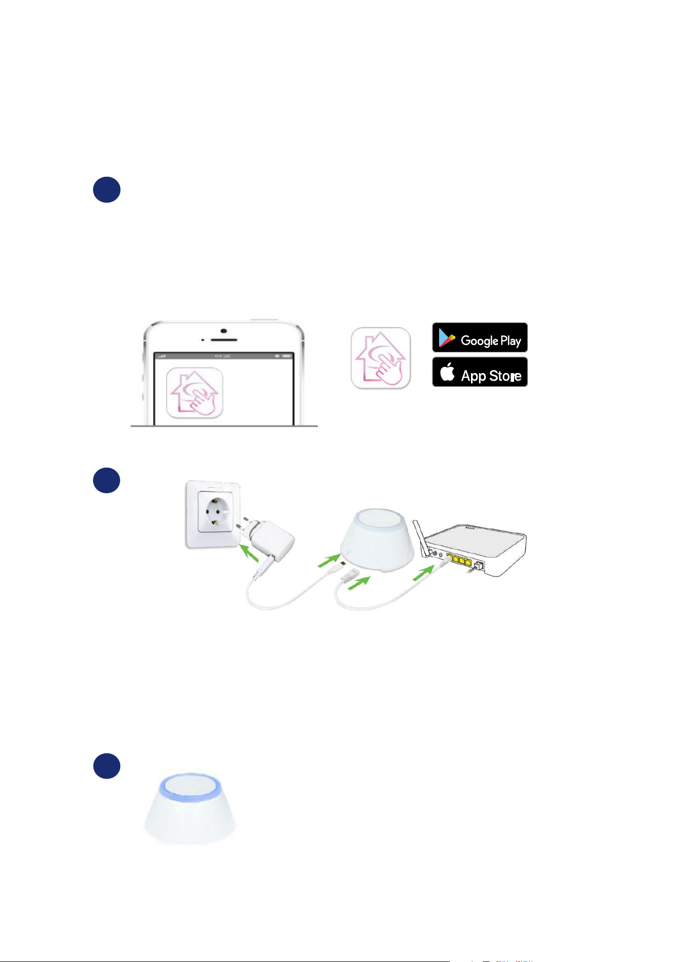
5. Installation by SALUS Smart Home application (ONLINE MODE)
5.1 General Informations about SALUS Smart Home application
Thanks to UGE600 Universal Gateway and SALUS Smart Home app system allows you to remote control of your heating system in any place you are
in the moment by smartphone, tablet or computer with Internet connection. Then you have also access to advanced functions of SQ610RF Quantum
thermostat. You can also create OneTouch rules to customize system to your needs.
SALUS
Smart Home
GET IT ON
Download on the
1
First make sure that you have downloaded the Salus Smart Home App from the Google Play or App
Store. You will need to follow a few easy steps to create an account and then link your QUANTUM to
the Universal Gateway and to the App.
You can also access the web version on:
http://eu.salusconnect.io/
To begin the pairing process the Gateway should be plugged into the power supply and connected
to the Internet. Also, make sure that the UGE600 is added to your Salus Smart Home App. For the
installation of the Universal Gateway, please refer to the UGE600 manual on salus-manuals.com
Make sure that your UGE600 Universal Gateway is added to the
App. The LED of the Gateway should be steady blue. Then go to
SQ610RF thermostat and begin paring process with the UGE600
and add it to the App.
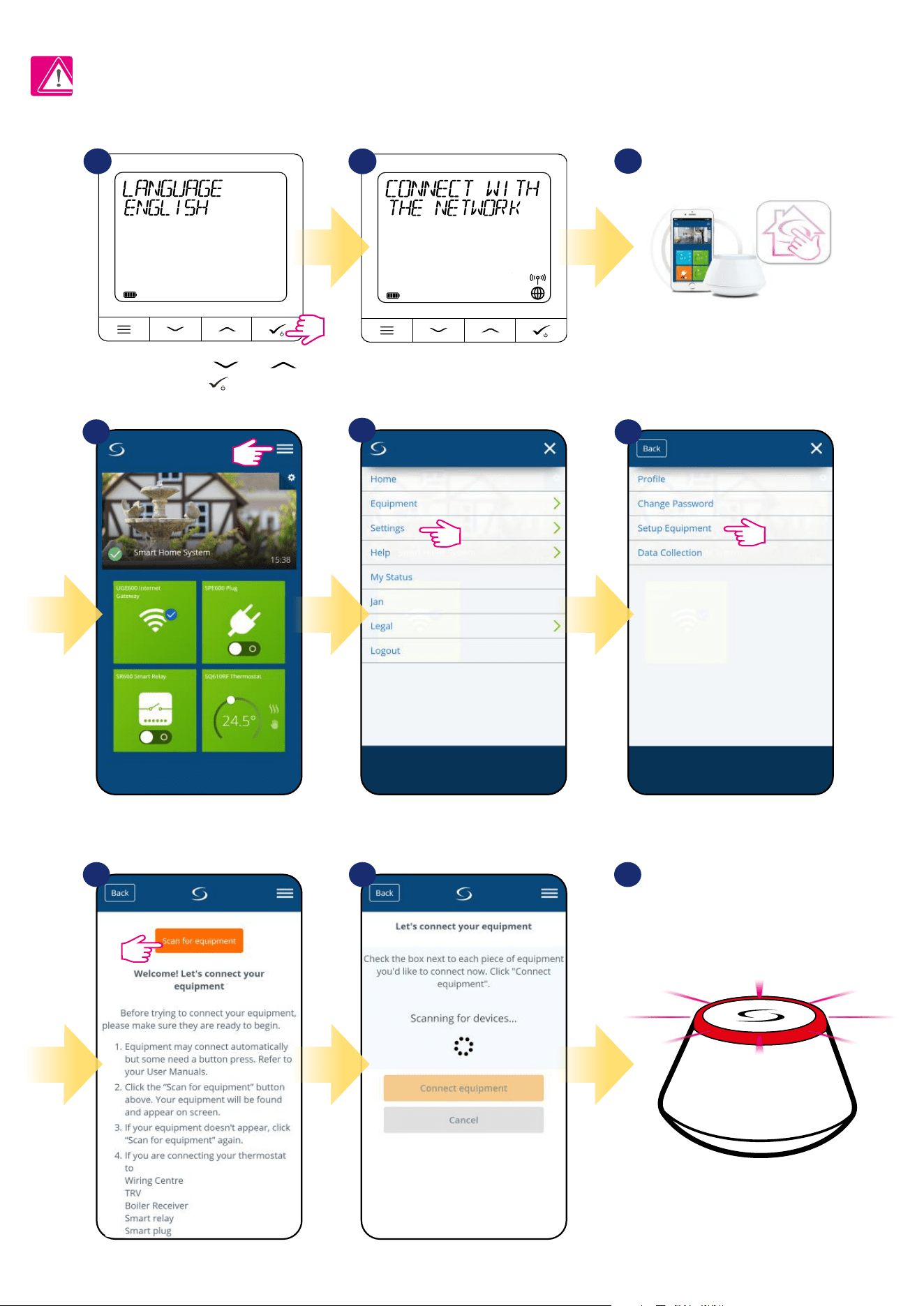
12
5.2 Pairing with underoor heating wiring centre (KL08RF/Control Box)
5
64
SALUS
SmartHome
Go to SALUS Smart Home app
3
Choose language by„ ” or „ ”
buttons. Conrm by
button.
Now thermostat is looking for the
signal from the coordinator...
Open main menu. Select „Settings”. Now enter to the „Setup Equipment”.
Press „Scan for equipment” button
7 8 9
App has started scanning...
1
2
For easier installation, please make sure you have already added underoor heating wiring centre (KL08RF/Control Box) to your ZigBee network (please
refer to the underoor heating wiring centre manual instruction).
Please note:
...Gateway has started ashing red and
searching for the thermostat...
13
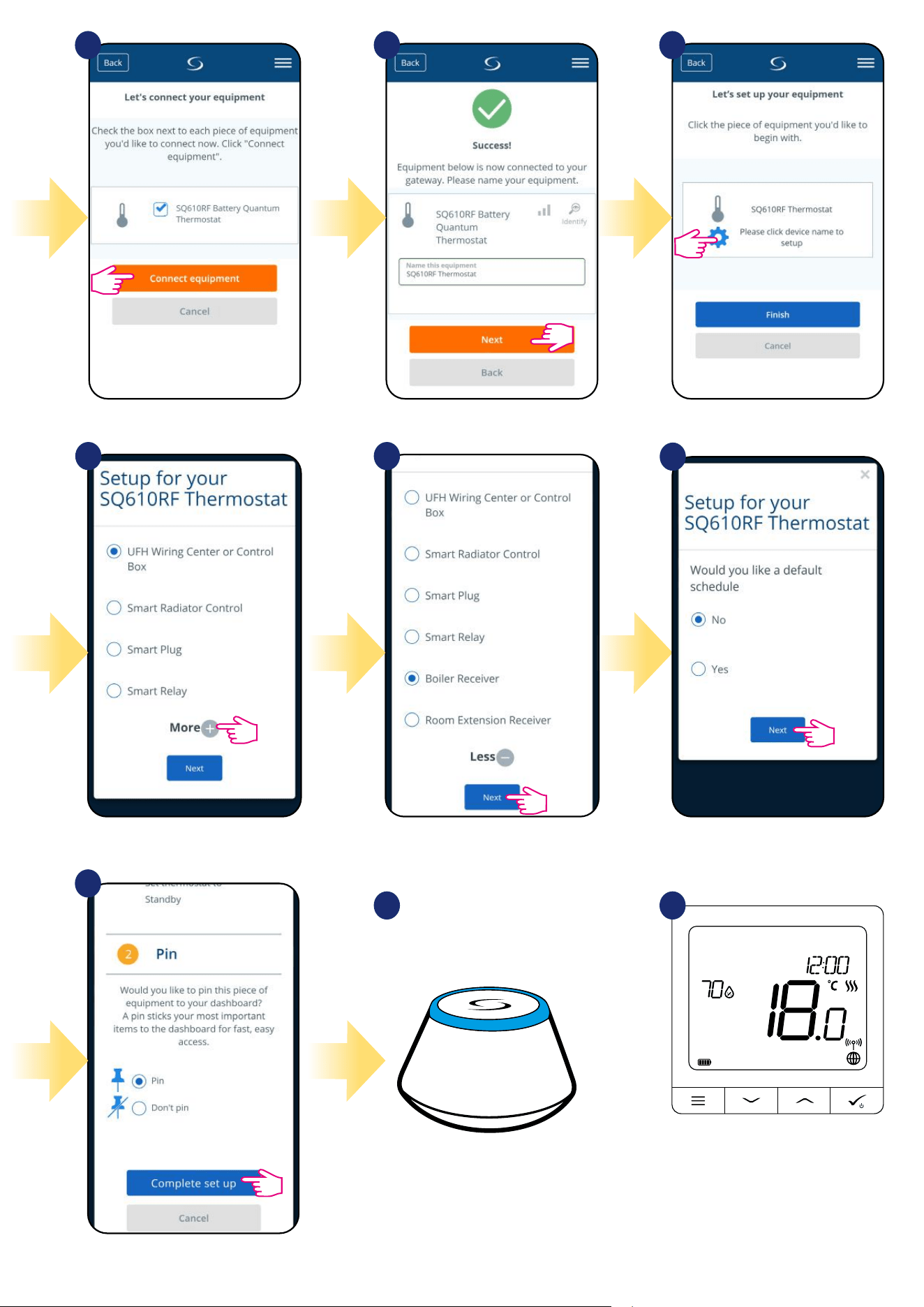
Thermostat is connected. Go to the
Smart Home app to congure it.
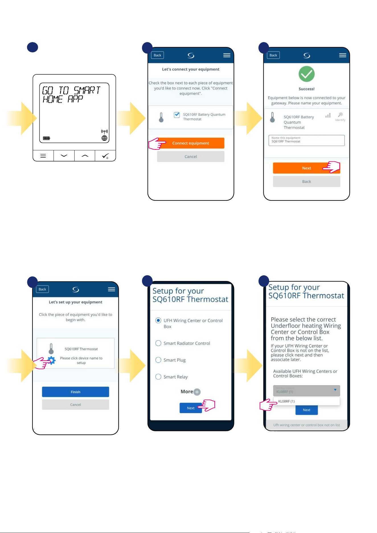
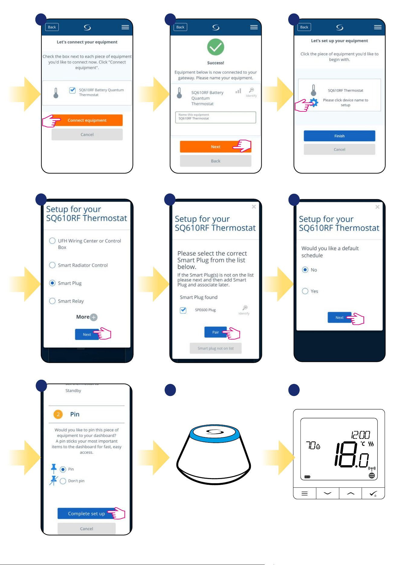
10
Select your thermostat and press
„Connect equipment” button.
Name your thermostat and go
„Next”...
Press gear icon.
11 12
13
14
15
Now choose „UFH Wiring Centre
or Control Box” option.
Select your KL08RF/Control Box added
before.
14
17
18
2019
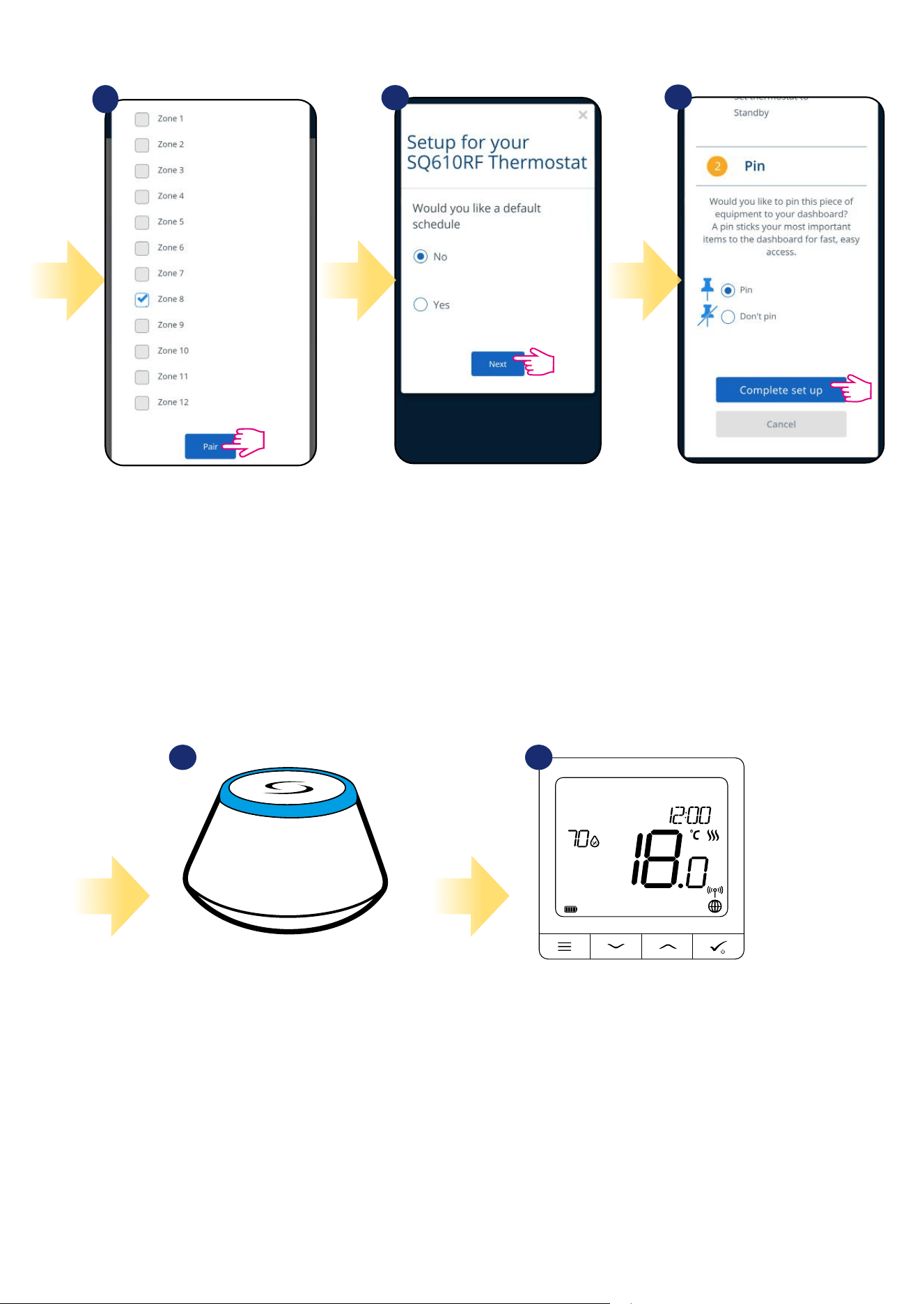
Pin thermostat to the main app screen
and complete set up.
Choose „No” if you want to set
your own schedule later or „Yes” if
default now.
After that thermostat will display
main screen.
Congratulations! You succesfully
congured SQ610RF Quantum
thermostat with KL08RF/Control
Box.
16
Select the zone which you want attribute to
your thermostat.
Remember that you can pair one thermostat
with more than one zone!
3
Gateway stop ashing and turn to steady
blue color which means pair process has
been nished.
15
5.3 Pairing with wireless TRV radiator head
1
SALUS
SmartHome
Go to SALUS Smart Home app
3
Choose language by„ ” or „ ”
buttons. Conrm by
button.
Now thermostat is looking for the
signal from the coordinator...
5
64
Open main menu. Select „Settings”. Now enter to the „Setup Equipment”.
Press „Scan for equipment” button.
7 8
App has started scanning...
9
2
For easier installation, please make sure you have already added wireless TRV radiator heads to your ZigBee network (please refer to the wireless TRV
radiator head manual instruction).
Please note:
...Gateway has started ashing red and
searching for the thermostat...
Thermostat is connected. Go to the
Smart Home app to congure it.
16
After that thermostat will display main
screen.
Congratulations! You succesfully
congured SQ610RF Quantum
Thermostat with Wireless TRV
radiator head.
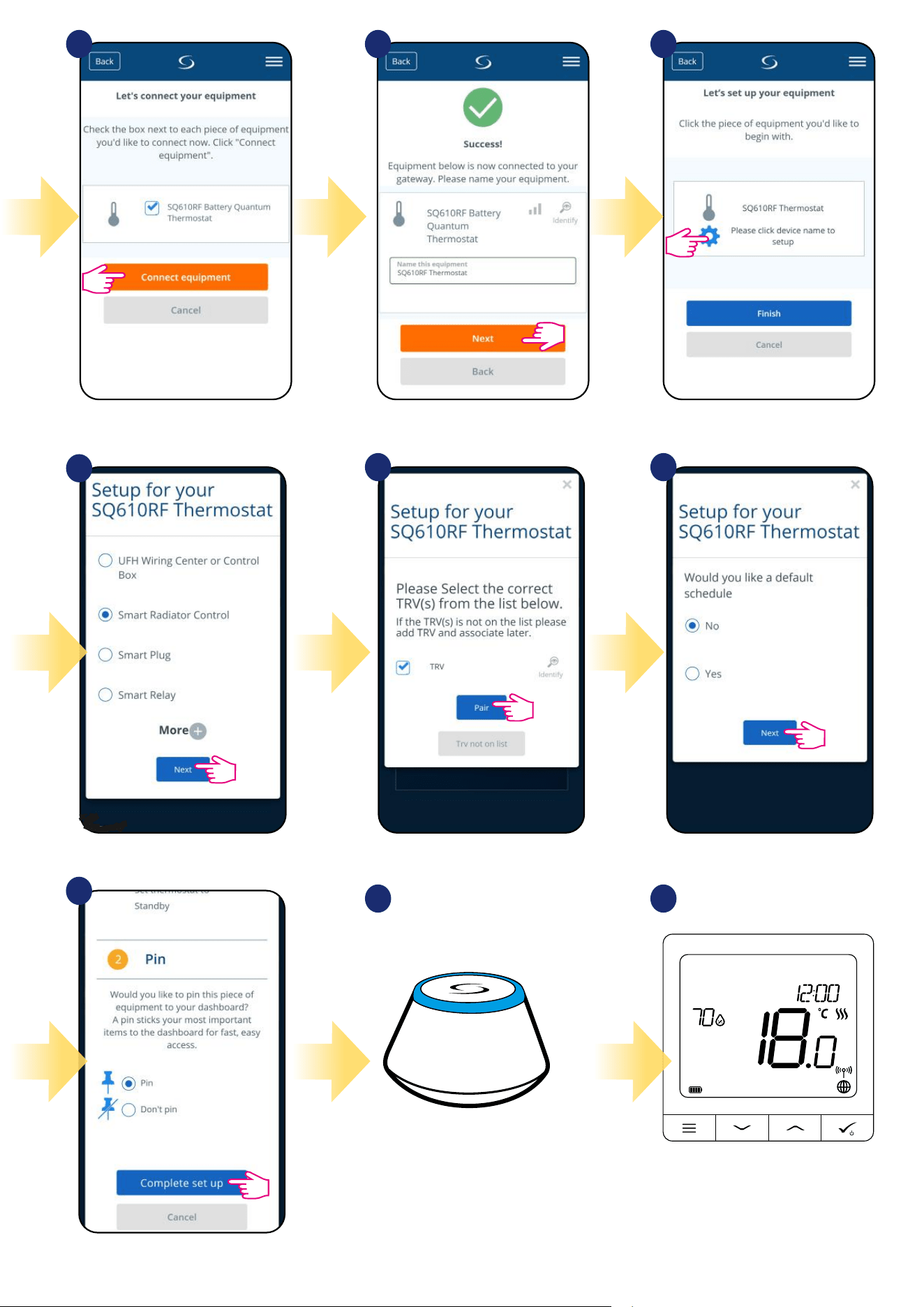
1817
13
14 15
16
Now choose Smart Radiator Control.
Select your TRV radiator
head from the list.
Choose „No” if you want to set
your own schedule later or „Yes” if
default now.
Pin thermostat to the main app
screen and complete set up.
Select your thermostat and press
„Connect equipment” button.
Name your thermostat and go
„Next”...
Press gear icon.
10 11 12
3
Gateway stop ashing and it turn to steady
blue color which means pair process has
been nished.
17
5.4 Pairing with Smart Plug SPE600
1
SALUS
SmartHome
Go to SALUS Smart Home app
3
Choose language by„ ” or „ ”
buttons. Conrm by
button.
Now thermostat is looking for the
signal from the coordinator...
5
64
Open main menu. Select „Settings”. Now enter to the „Setup Equipment”.
Press „Scan for equipment” button.
7 8
App has started scanning...
9
2
For easier installation, please make sure you have already added Smart Plug SPE600 to your ZigBee network (please refer to the Smart Plug SPE600
manual instruction).
Please note:
Thermostat is connected. Go to the
Smart Home app to congure it.
...Gateway has started ashing red and
searching for the thermostat...
18
Select your thermostat and press
„Connect equipment” button.
Name your thermostat and go
„Next”...
Press gear icon.
10 11 12
After that thermostat will display
main screen.
Congratulations! You succesfully
congured SQ610RF Quantum
Thermostat with Smart Plug SPE600.
1817
16
Choose „No” if you want to set
your own schedule later or „Yes” if
default now.
Pin thermostat to the main app
screen and complete set up.
13
Now choose Smart Plug.
Select your Smart Plug from the list.
14
15
3
Gateway stop ashing and it turn to steady
blue color which means pair process has
been nished.
19
5.5 Pairing with Smart Relay SR600
1
SALUS
SmartHome
Go to SALUS Smart Home app
3
Choose language by„ ” or „ ”
buttons. Conrm by
button.
Now thermostat is looking for the
signal from the coordinator...
5
64
Open main menu. Select „Settings”. Now enter to the „Setup Equipment”.
Press „Scan for equipment” button.
7 8
App has started scanning...
9
2
For easier installation, please make sure you have already added Smart Relay SR600 to your ZigBee network (please refer to the Smart Relay SR600
manual instruction).
Please note:
Thermostat is connected. Go to the
Smart Home app to congure it.
...Gateway has started ashing red and
searching for the thermostat...
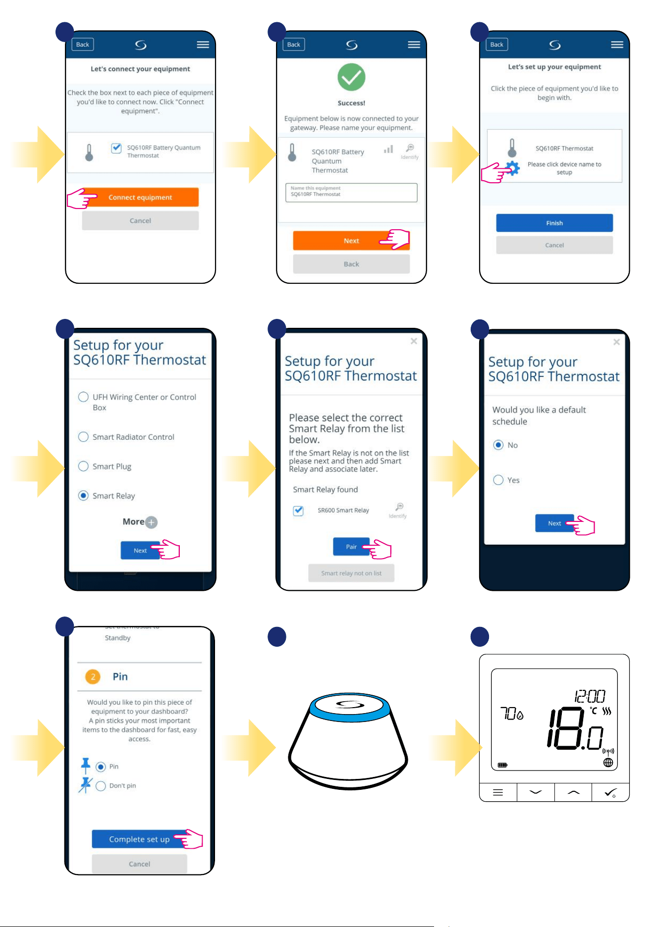
20
Select your thermostat and press
„Connect equipment” button.
Name your thermostat and go
„Next”...
Press gear icon.
10 11 12
After that thermostat will display
main screen.
Congratulations! You succesfully
congured SQ610RF Quantum
Thermostat with Smart Relay SR600.
1817
16
Choose „No” if you want to set
your own schedule later or „Yes” if
default now.
Pin thermostat to the main app
screen and complete set up.
13
Now choose Smart Relay.
Select your Smart Relay from the list.
14
15
3
Gateway stop ashing and it turn to steady
blue color which means pair process has
been nished.

21
5.6 Pairing with RX10RF receiver
1
SALUS
SmartHome
Go to SALUS Smart Home app
3
Choose language by„ ” or „ ”
buttons. Conrm by
button.
Now thermostat is looking for the
signal from the coordinator...
5 64
Open main menu. Select „Settings”. Now enter to the „Setup Equipment”.
Press „Scan for equipment” button.
7 8
App has started scanning...
9
2
For easier installation, please make sure you have already added RX10RF receiver to your ZigBee network (please refer to the RX10RF receiver manual
instruction).
Please note:
Thermostat is connected. Go to the
Smart Home app to congure it.
...Gateway has started ashing red and
searching for the thermostat...
22
Select your thermostat and press
„Connect equipment” button.
Name your thermostat and go
„Next”...
Press gear icon.
10 11 12
After that thermostat will display
main screen.
Congratulations! You succesfully
congured SQ610RF Quantum
Thermostat with RX10RF boiler
receiver.
1817
16
Choose „No” if you want to set
your own schedule later or „Yes” if
default now.
Pin thermostat to the main app
screen and complete set up.
13
Choose „More” to expand the menu.
Now choose Boiler Receiver. If RX10RF is set as
„RX1” then choose option „Boiler Receiver”. If as a
„RX2” then select „Room Extension Receiver”.
14
15
3
Gateway stop ashing and it turn to steady
blue color which means pair process has
been nished.
23
6. OPERATING in ONLINE MODE (by app)
6.1 General Informations
This section will show how to use your SQ610RF Quantum thermostat with the UGE600 Universal Gateway and the Salus Smart Home App.
In order to do that, you will need a Salus UG600/UGE600 Universal Gateway, the Salus Smart Home App and Internet connection.
Controlling your thermostat via the App gives you a lot of freedom and the possibilities to manage the temperature in your house/oce remotely
(Smart Home app is available for Android/iOS mobile devices or Internet browser).
6.2 App icons description
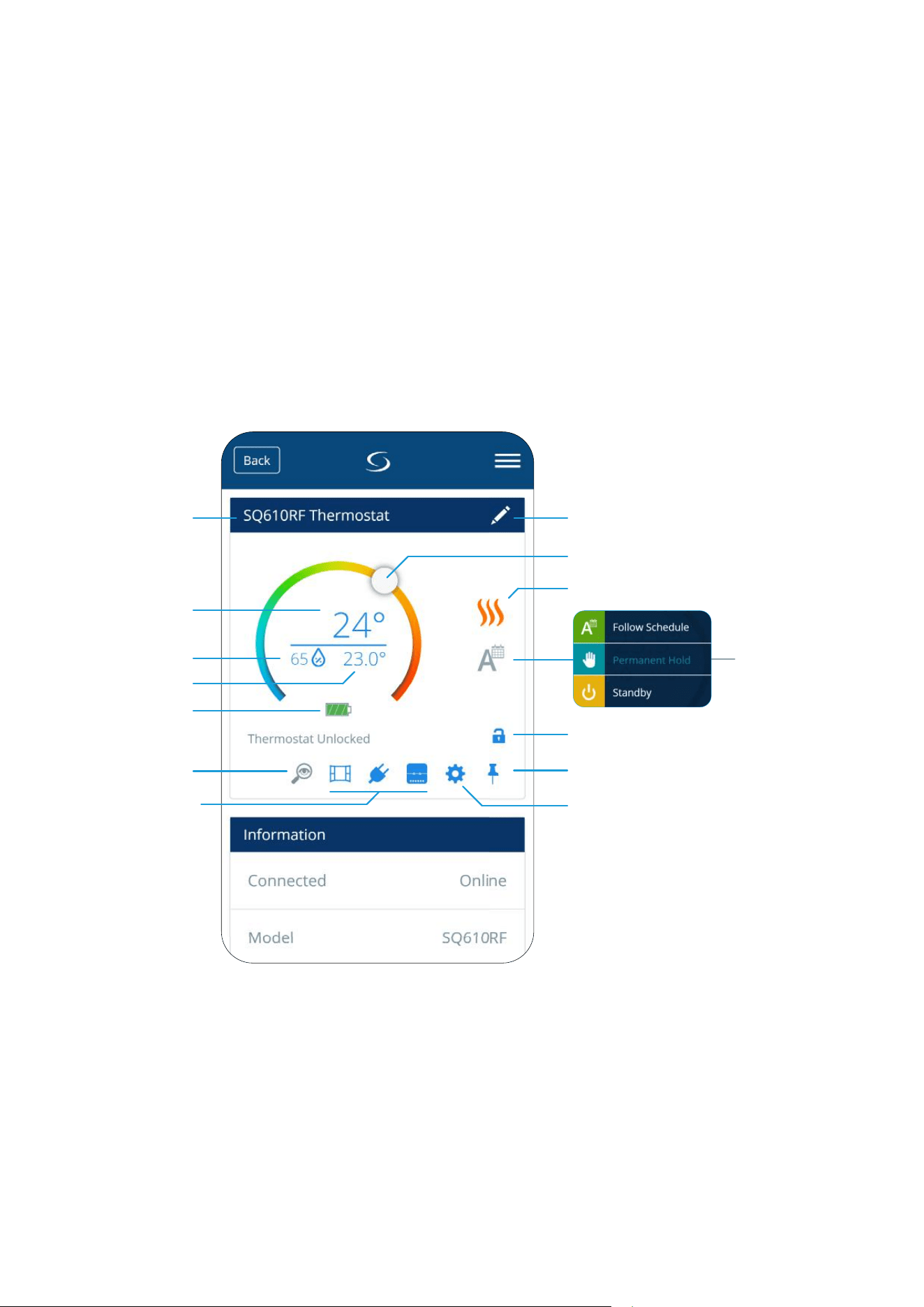
View from Quantum thermostat SQ610RF menu in SALUS Smart Home application:
Thermostat mode
selection
Thermostat Heat/Cool mode indicator
Setpoint temperature slider
Thermostat name change tool
Thermostat locking/unlocking function
Pin/Unpin thermostat to/from
main application dashboard
Additional thermostat settings (including
advanced installer parameters)
Icons of devices like
window/door sensors
(OS600/SW600), Smart
Plug (SPE600) and SR600
smart relay. You can see
them only when these
devices are
paired with system.
Through these icons you can
pair Thermostat SQ610RF
fast with selected device.
Room temperature
Battery status
indicator
Identication tool
Thermostat name
Setpoint temperature
Humidity indicator
(hygrometer)
24
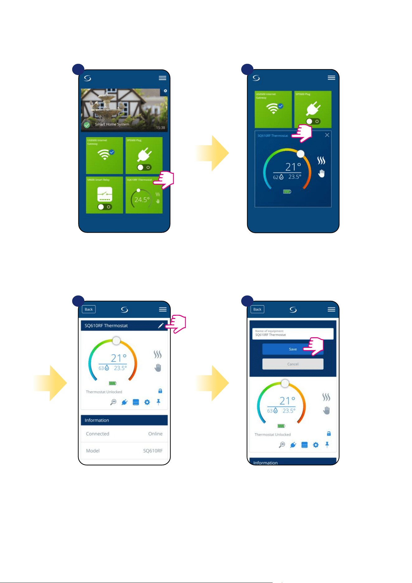
6.3 Change thermostat name (pencil tool)
Name your termostat and
conrm it by „Save” button.
Click on the pencil icon.
Select the thermostat in
the main app menu.
1 2
3 4
Press the thermostat’s name.
25
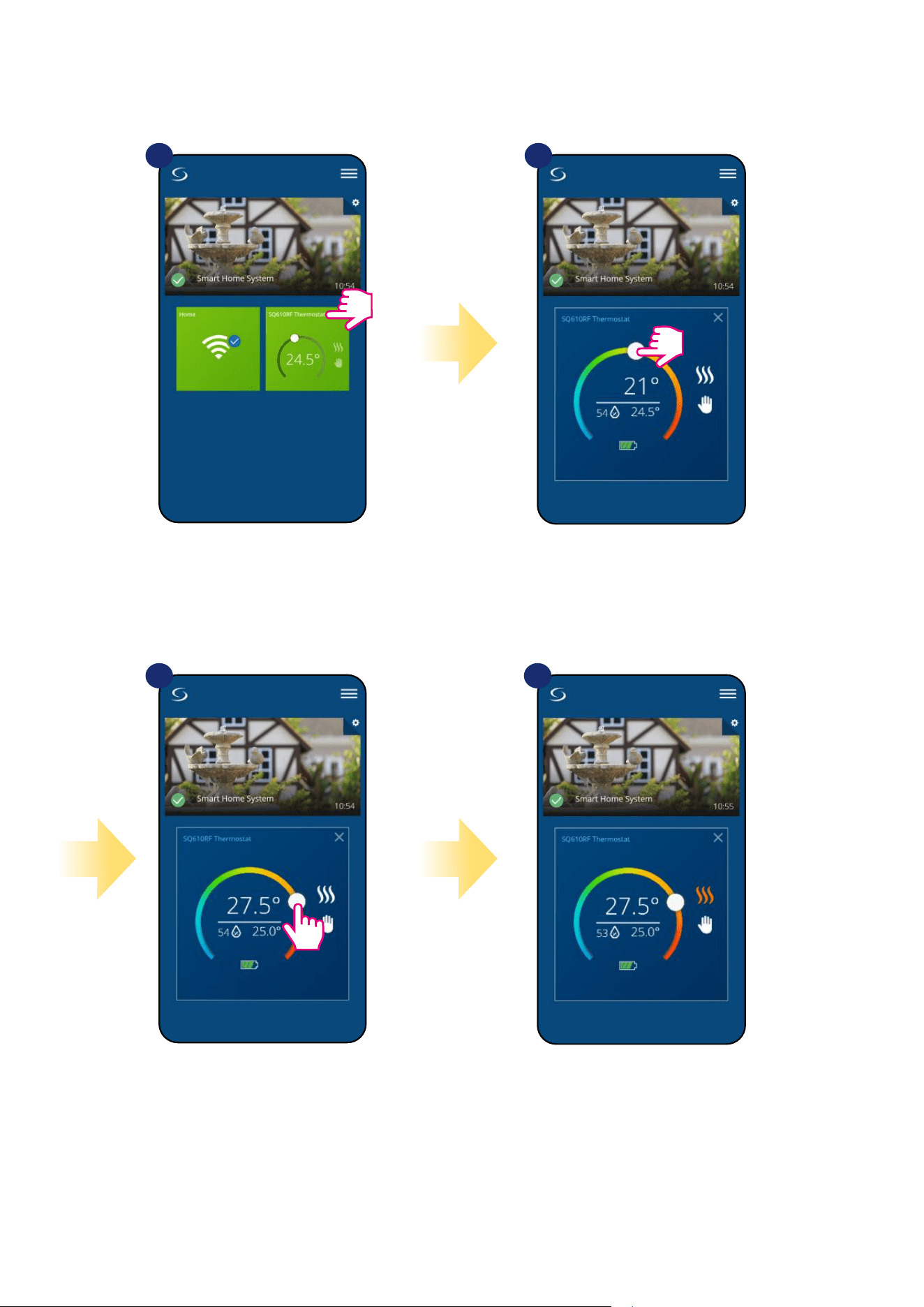
6.4 Setpoint temperature change
You can change the setpoint by sliding the cursor to left/right on your App. On your App screen, the setpoint temperature is the number displayed in a
larger font.
Select the thermostat in
the main app menu.
1 2
3 4
Old setpoint value.
New setpoint value.
Thermostat has started heating
(ame icon changed colour to
orange from white).
26
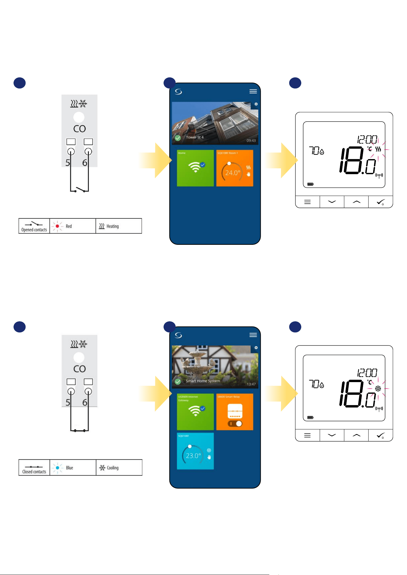
6.5 Heat/Cool mode change (KL08RF connection)
SQ610RF Quantum thermostat could be a heating device or cooling device. Default thermostat is set for heating. To set cool mode you have to
insert the jumper into „CO” terminal. Look at the instructions below:
On the thermostat display you
will see „Snow” icon. When
thermostat is calling for cooling
then icon is animating.
When thermostat is calling for
heating then icon is animating.
In the application you will see blue thermostat tile
with „Snow” icon when cooling mode is on.
1 2
When there is jumper at „CO” terminal KL08RF
is automatically working in cooling mode.
3
1 2 3
When there is no jumper at „CO” terminal KL08RF
is automatically working in heating mode.
In the application you will see orange thermostat
tile with „Flame” icon when heating mode is on.
COOLING MODE:
HEATING MODE:
27
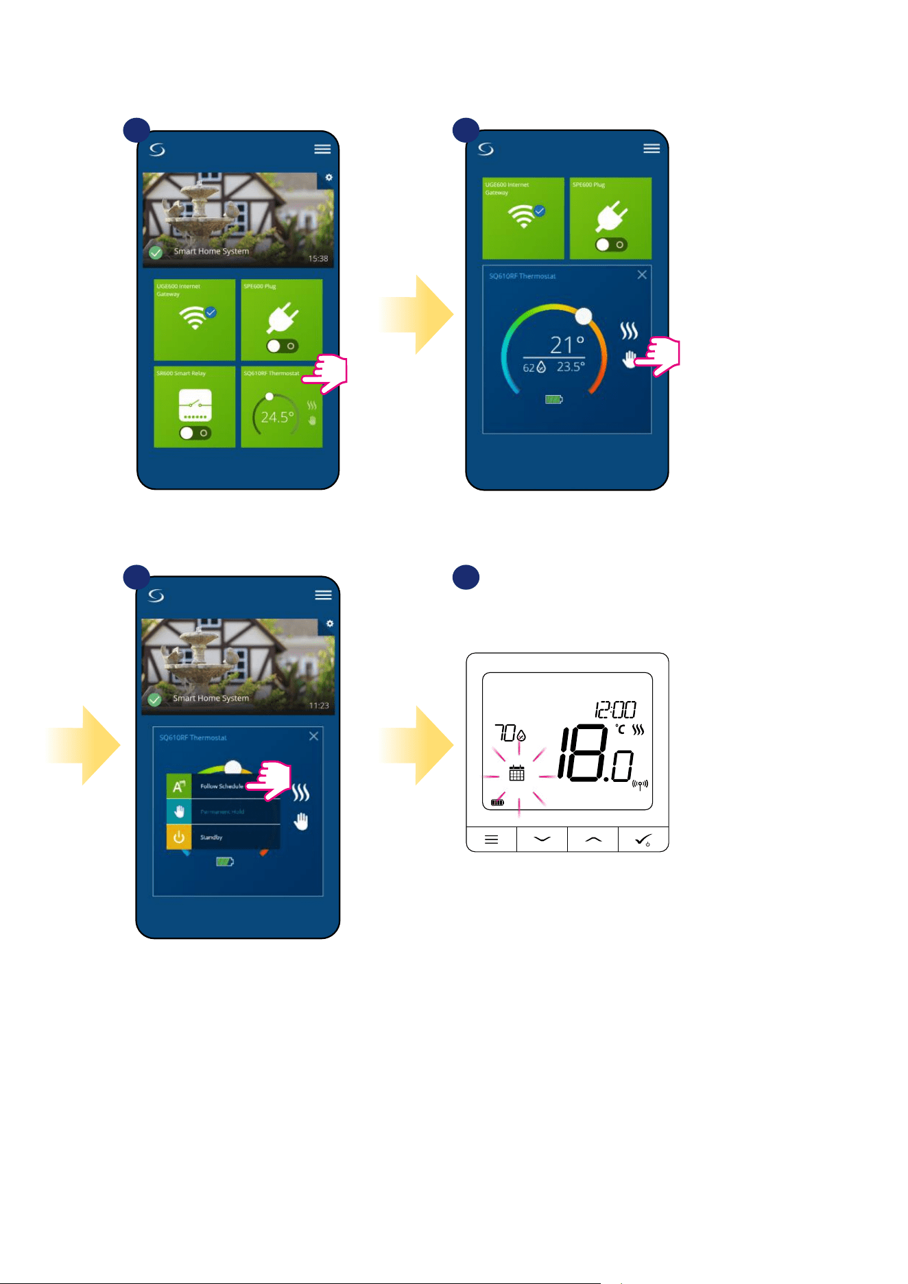
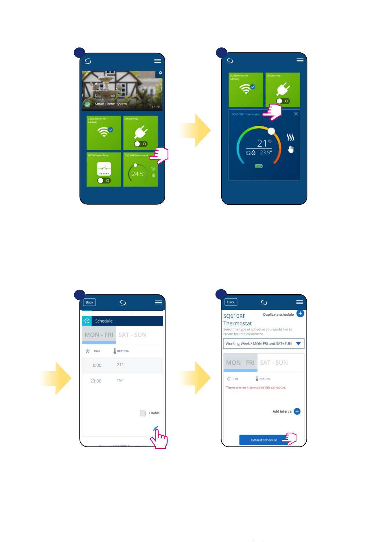
The SQ610RF Quantum Thermostat gives you the possibility to set schedules for the thermostat. You can add up to 6 programs during
one day, by selecting the program's start time and temperature. You can choose from 3 dierent schedule congurations:
• 5+2 (5 days same program + 2 days same program)
• Individual every week day
• All 7 days same program
Additionally, you can choose to set the Default schedules that already exist in the App, or to modify them according to your preferences.
The schedules are displayed on the bottom of screen of your App on the selected thermostat. You can activate the schedules by pressing
the Follow Schedule icon on your App. Once activated, the calendar icon will appear on your screen.
Choose „Follow Schedule”
work mode.
6.6 Thermostat modes
6.6.1 Schedule Mode
To activate Schedule Mode:
Select thermostat in the
main app menu.
Click on the work mode icon.
1 2
3
When schedule mode is
on, then calendar icon will
display.
4
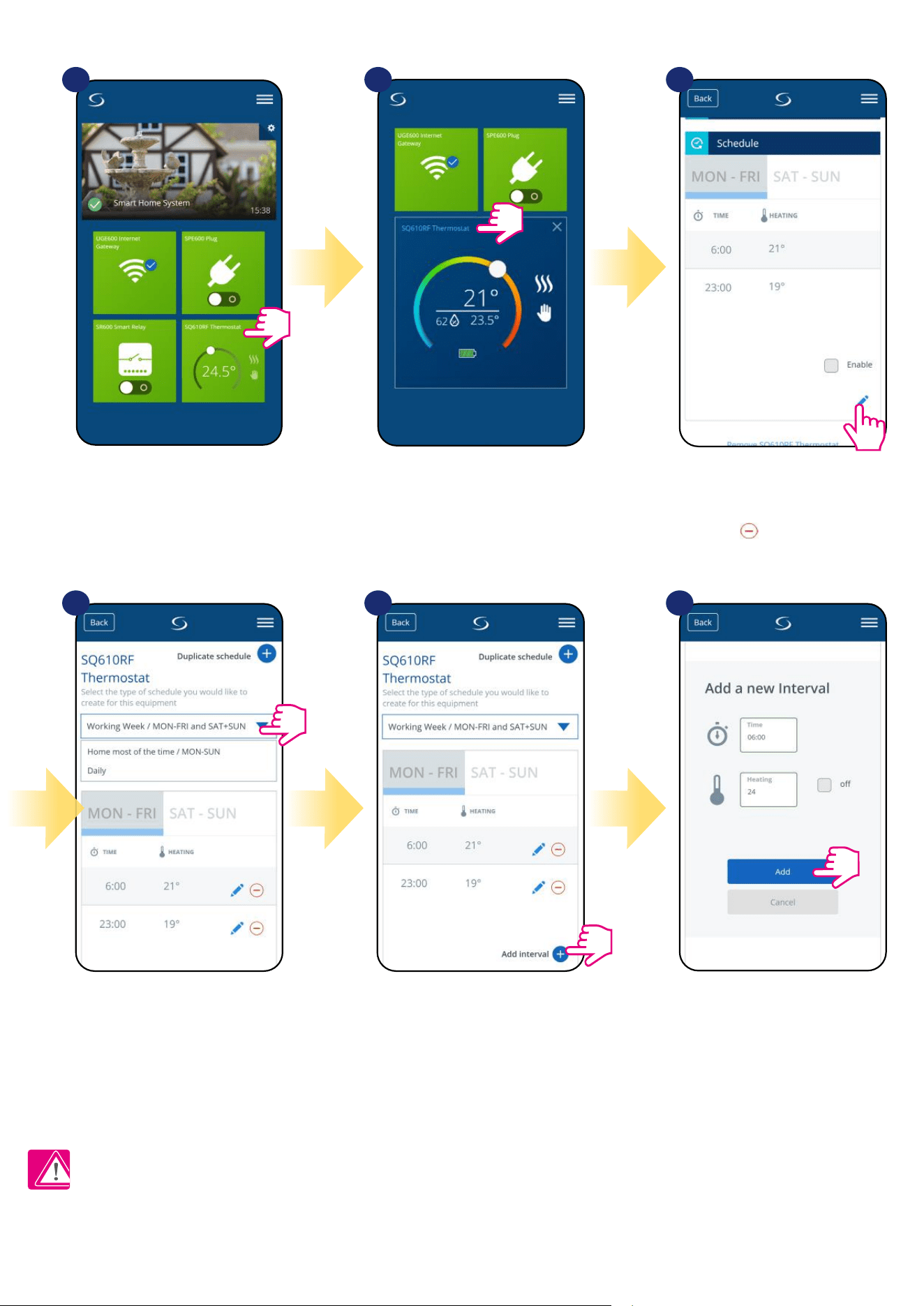
28
Select thermostat in the
main app menu.
1 2 3
Scroll down and press pencil button.
As you can see there is default
schedule. You can delete all default
intervals by button.
Choose for which days you want to program your
schedule.
• 5+2 (5 days same program + 2 days same program)
(MON-FRI + SAT-SUN)
• Individual every week day (Daily)
• All 7 days same program (MON-SUN)
After days period selection use
„Add interval” option to add your
intervals to the schedule.
Then add a start time and
temperature setpoint, after
all - conrm by pressing „Add”
button.
4 5 6
TO SET THE SCHEDULE IN THE APP:
Please note:
You can add as many intervals as you wish by repeating the procedure described from steps 3 to 6. The procedure is the same for all 3 schedule
congurations. You can customize the programs on the thermostat in any way you want.
Press thermostat’s name.
29
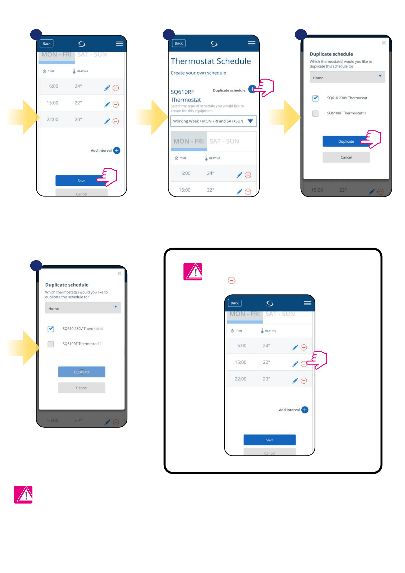
After you’ve added all the intervals,
press „Save” to save it. Your schedule
has been saved and set.
7
10
8 9
PLEASE NOTE: To delete any interval in the schedule
just use button next to selected interval.
ADDITIONALLY: You can
duplicate the same schedule for
other thermostat’s. Click on the
„Duplicate schedule” option.
Select thermostat for which you
want to duplicate the schedule.
Now app is saving your choice and
after it you will have the same
schedule for thermostat’s you’ve
selected.
Please note:
When thermostat has no schedule (or it has been deleted) then it maintains a constant temperature 21 °C (in „Follow Schedule” mode).
30
To set default schedule use „Default schedule”
button. It will remove all current intervals and
it will set default schedule.
4
Select thermostat in the
main app menu.
1 2
3
Scroll down and press pencil icon.
TO SET DEFAULT SCHEDULE:
Press thermostat’s name.
31
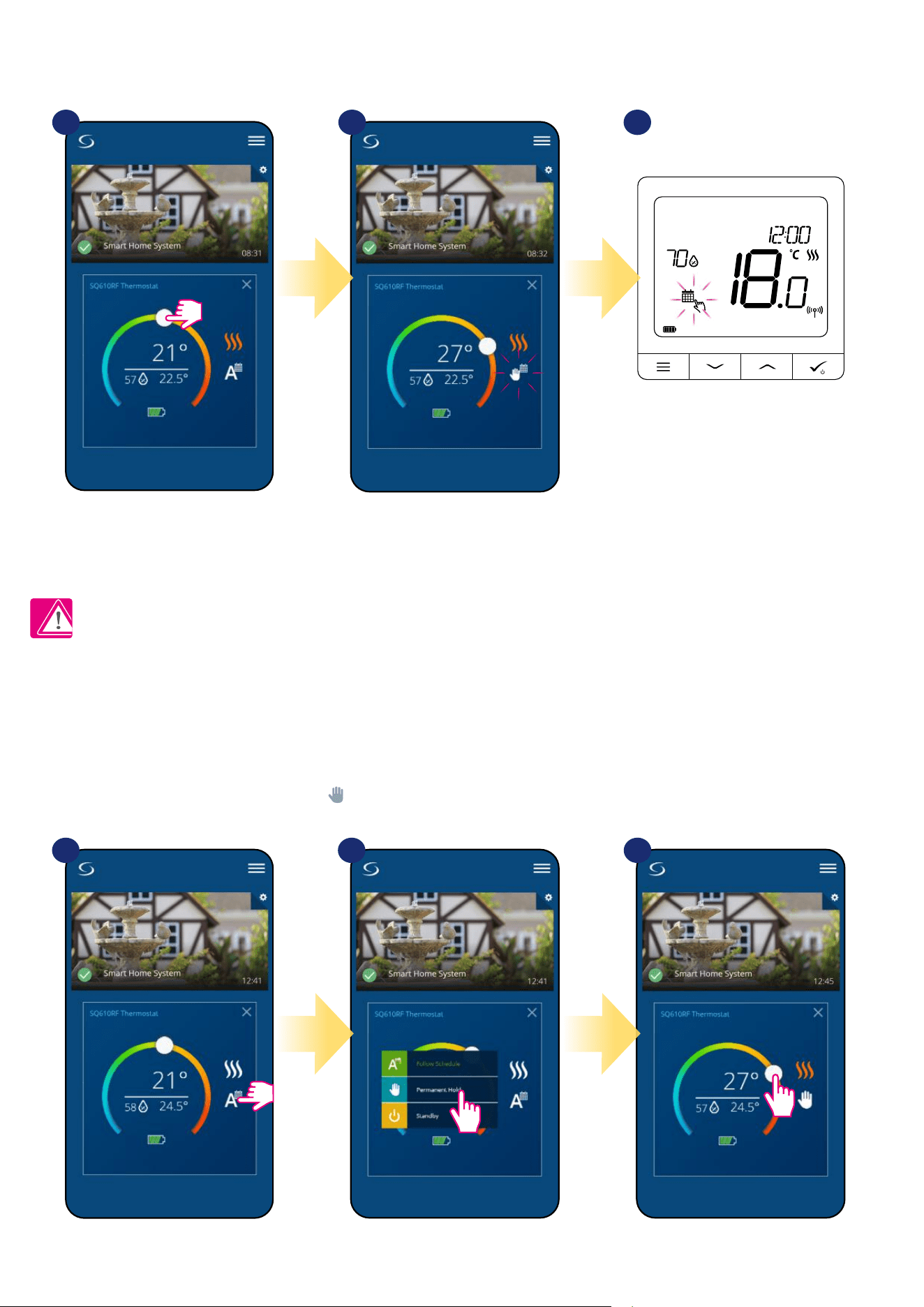
6.6.3 Manual mode
If the thermostat follows a schedule or is in Standby mode, user can change the operating mode to the manual mode. In manual mode
thermostat will maintain setpoint temperature until user will manually change it to a new value or select a new operating mode. When
thermostat works in manual mode, the hand icon will be displayed in the app screen.
Press thermostat’s work modes icon. Select „Permanent Hold” mode. Hand icon conrms that thermostat is
in manual mode.
1 2 2
6.6.2 Temporary override mode
Temporary override mode means manual temperature change during active schedule mode:
NOTE: Temporary override mode will be maintained until next program will come, as it has been set in the schedule.
Use slider to set new setpoint
temperature.
When you have overwritten the temperature
then hand icon next will appear to calendar
which means that temporary override mode is
working until next schedule program.
When you overwrote temperature then
on the display you will see calendar
with hand icon.
31 2
32
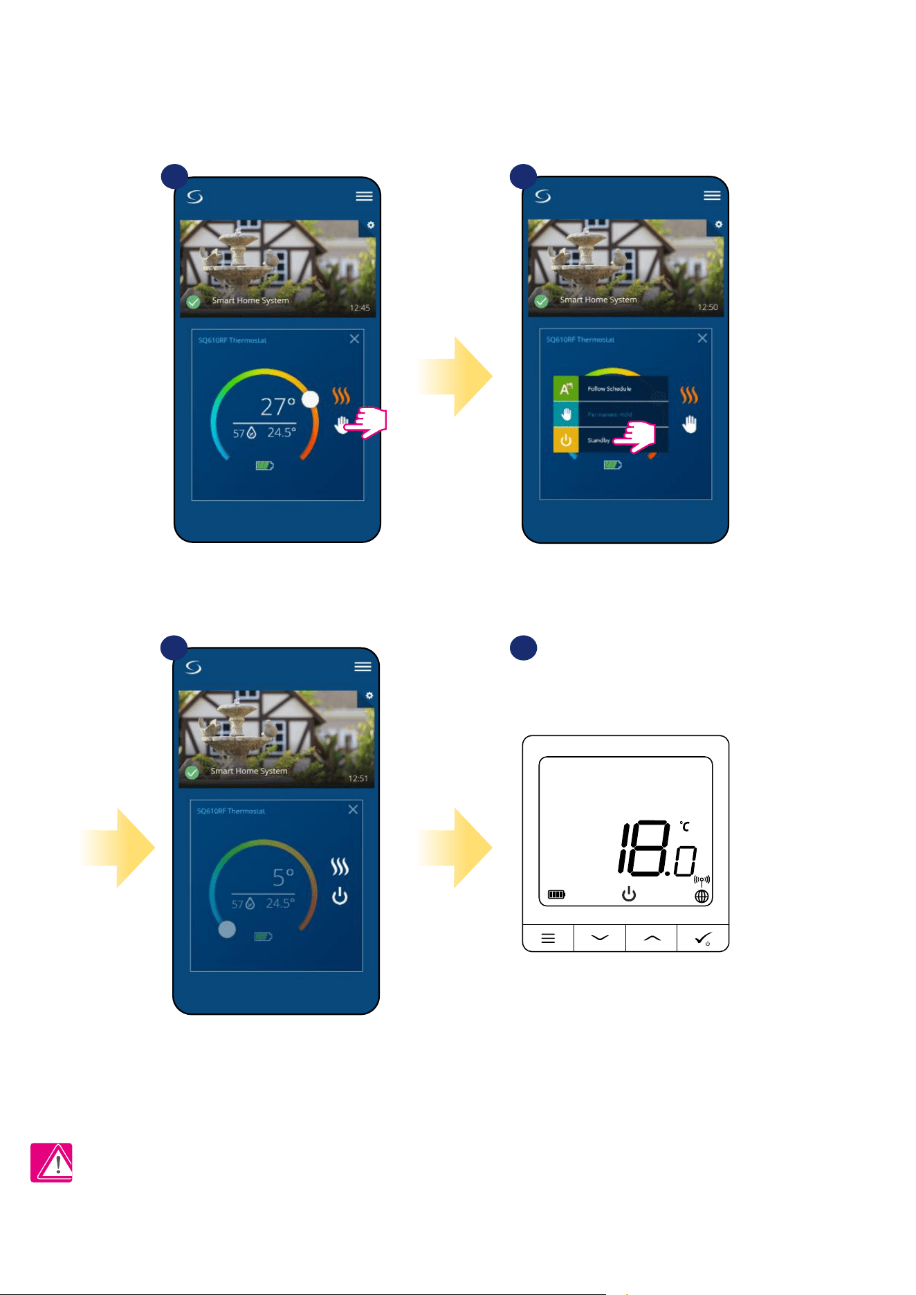
6.6.4 Standby Mode
In Standby mode the thermostat is displaying actual room temperature and maintain „Standby” setpoint temperature specied in thermostat
settings (please refer to chapter 8.3). When thermostat works in Standby mode then you have no possibilities to change temperature setpoint. To
activate. Standby mode online please followe steps below:
Note: When the thermostat exits Standby mode, previous mode will be restored.
Press thermostat’s work modes icon.
Select „Standby” mode.
Thermostat is in Standby Mode.
1 2
3 4
You can also see that thermostat is
in Standby mode on the display.
33
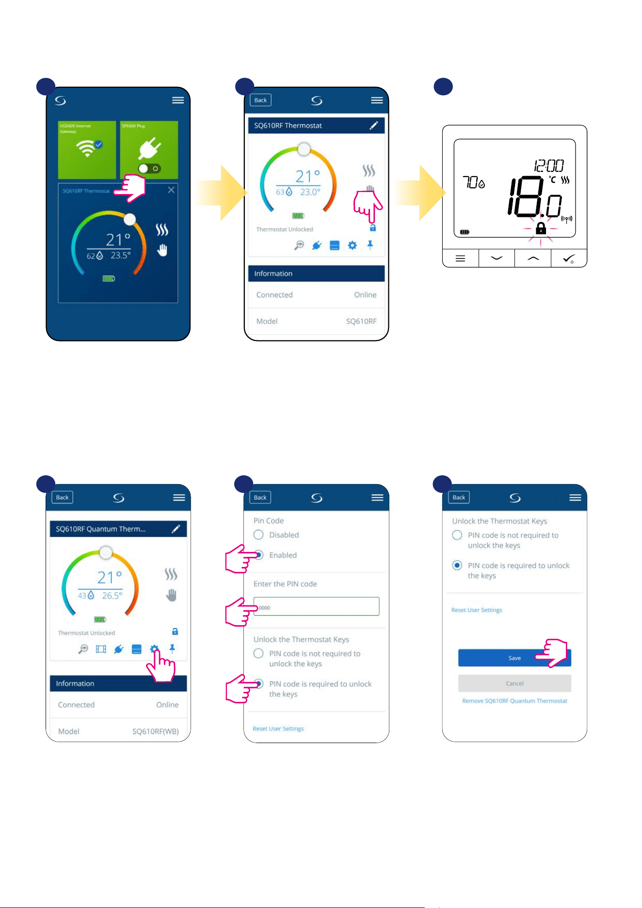
6.7 Key Lock Function
You can lock/unlock buttons in your thermostat by application.
If buttons are locked/unlocked then also
you can see it on thermostat display
(„padlock” icon will display).
Click on the „padlock” icon to
lock/unlock thermostat buttons.
1
2 3
Press thermostat’s name.
Enter the settings. Scroll down and enable the pin code.
Then enter the PIN code.
Additionally you can set PIN code
for keys. Which means you’ll have
to enter code every time when
you want to unlock keys from the
thermostat side.
After all, press „Save” button to set
PIN code and save settings.
When thermostat is locked you can unlock it from app or from the device side (please refer to chapter 4.2). As an option you can lock thermostat by PIN,
so it will be not possible to unlock it from the device side. To lock thermostat by PIN, please follow steps below:
1 2 3
1.
2.
3.
34
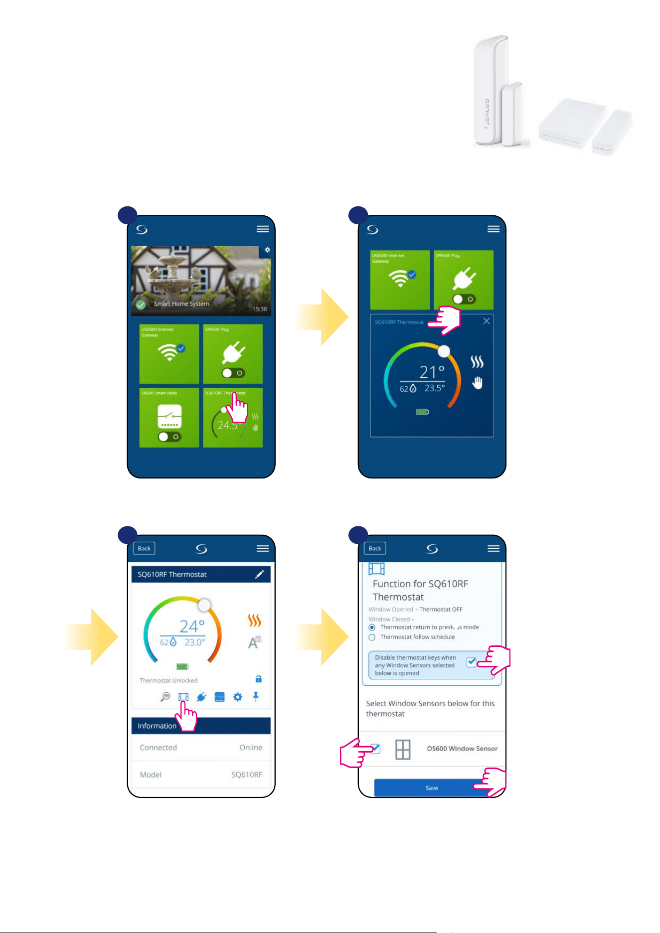
6.8 Compatibility with window/door sensor OS600 / SW600
SQ610RF Quantum thermostat paired with window/door sensor OS600/SW600 allows to create
OneTouch rules when window/door is opened or closed. If thermostat will receive information from
window/door sensor (that window has been opened for example) then OneTouch rule you programmed
will turn o heating until window close. If you want to have acces to this function then rst you have to add
window/door sensor OS600 or SW600 (please refer to the OS600 or SW600 manual instruction).
To pair window/door sensor OS600/SW600 with SQ610RF Quantum thermostat please follow steps below:
Mark sensors which you want to link together with the
thermostat. You can additionaly lock buttons on thermostat
when window is opened by marking option above.
Press „Save” button to nish pair process...
1 2
3
4
Select the thermostat in
the main app menu.
Press thermostat’s name.
Choose the window icon.
35
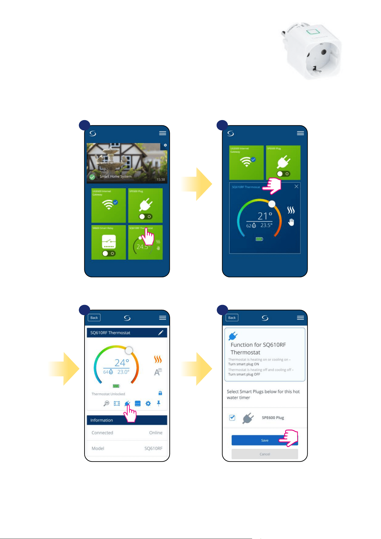
6.9 Compatibility with Smart Plug SPE600
SQ610RF Quantum thermostat paired with SPE600 Smart Plug allows to turn on/o any electric
device eg. pump, radiator or valve with actuator. When thermostat start heating then plug will turn on
device (or turn o when there is no need to heat). If you want to have acces to this function then rst
you have to add SPE600 Smart Plug to the SALUS SmartHome system (please refer to the SPE600
manual instruction).
To pair SPE600 Smart Plug with SQ610RF Quantum thermostat please follow steps below:
Choose plugs which you want to add to the
thermostat. Press „Save” button to nish pair
process...
Choose the plug icon.
1 2
Select the thermostat in
the main app menu.
3 4
Press thermostat’s name.
36
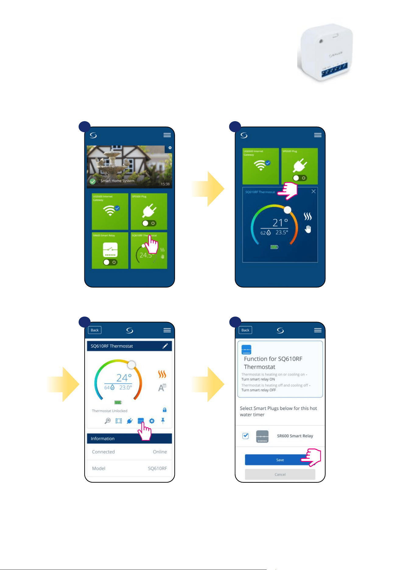
6.10 Compatibility with Smart Relay SR600
SQ610RF Quantum thermostat paired with Smart Relay SR600 allows to wireless control of eg.
radiator, pump, boiler. When thermostat start heating then SR600 Smart Relay will turn on device
(or turn o when there is no need to heat). If you want to have acces to this function then rst you
have to add SR600 Smart Relay to the SALUS SmartHome system (please refer to the SR600
manual instruction).
To pair SR600 Smart Relay with SQ610RF Quantum thermostat please follow steps below:
Choose SR600 relays which you want to add
to the thermostat. Press „Save” button to
nish pair process...
Press the relay icon.
1 2
Select the thermostat in
the main app menu.
3
4
Press thermostat’s name.
37
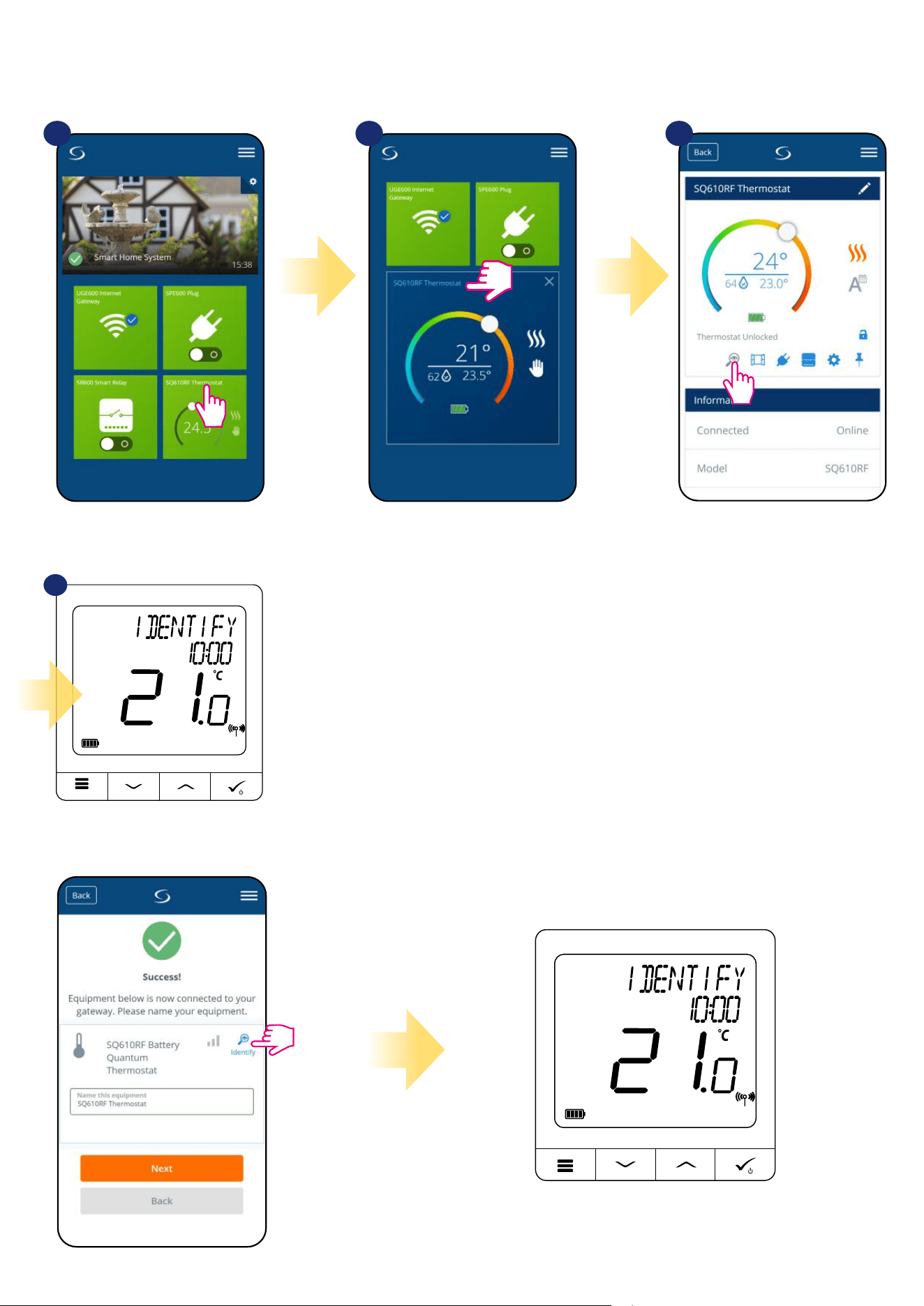
6.11 Identication mode
Identication mode can be useful when we are pairing more than one device in one moment and we don’t know which device is which. Beyond, if our
system include more that one UGE600 Universal Gateway then we can easily identify which device is paired with which gateway.
In the Identication mode thermostat’s
display will start ashing „IDENTIFY”
information for 10 minutes.
You can also identify your device during thermostat’s pairing process:
4
Use the magnifying glass icon.
Click on the magnifying glass icon.
1 2
Select the thermostat in
the main app menu.
3
Press thermostat’s name.
38
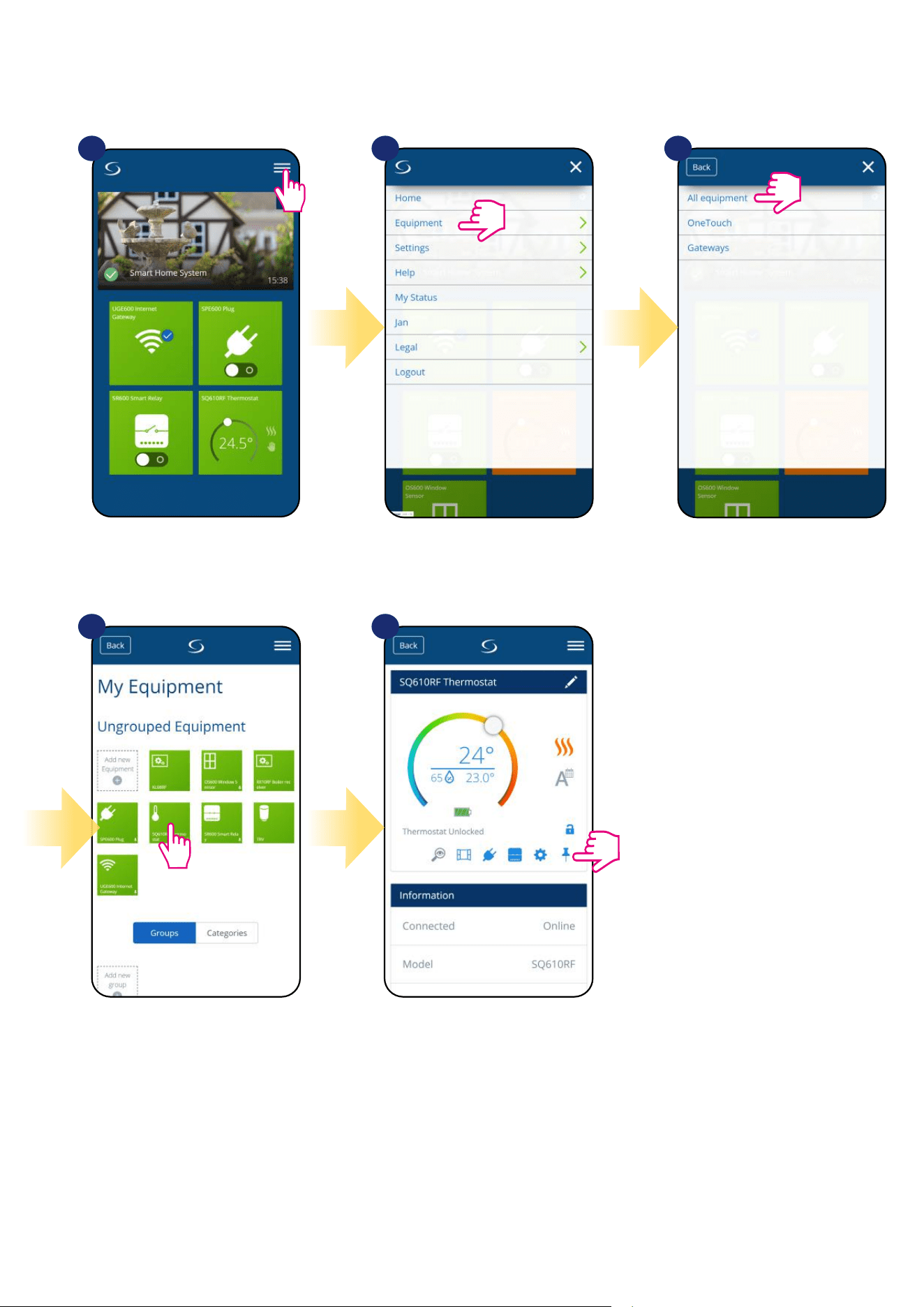
6.12 Pinning/unpinning thermostat to/from application dashboard
To pin/unpin thermostat from dashboard in Smart Home application please follow steps below:
1 2 3
Open main menu in the app. Select equipment. Select All equipment option.
Select your SQ610RF thermostat. Press on the „Pin” icon to pin/unpin
thermostat to/from the app dashboard.
4 5
39
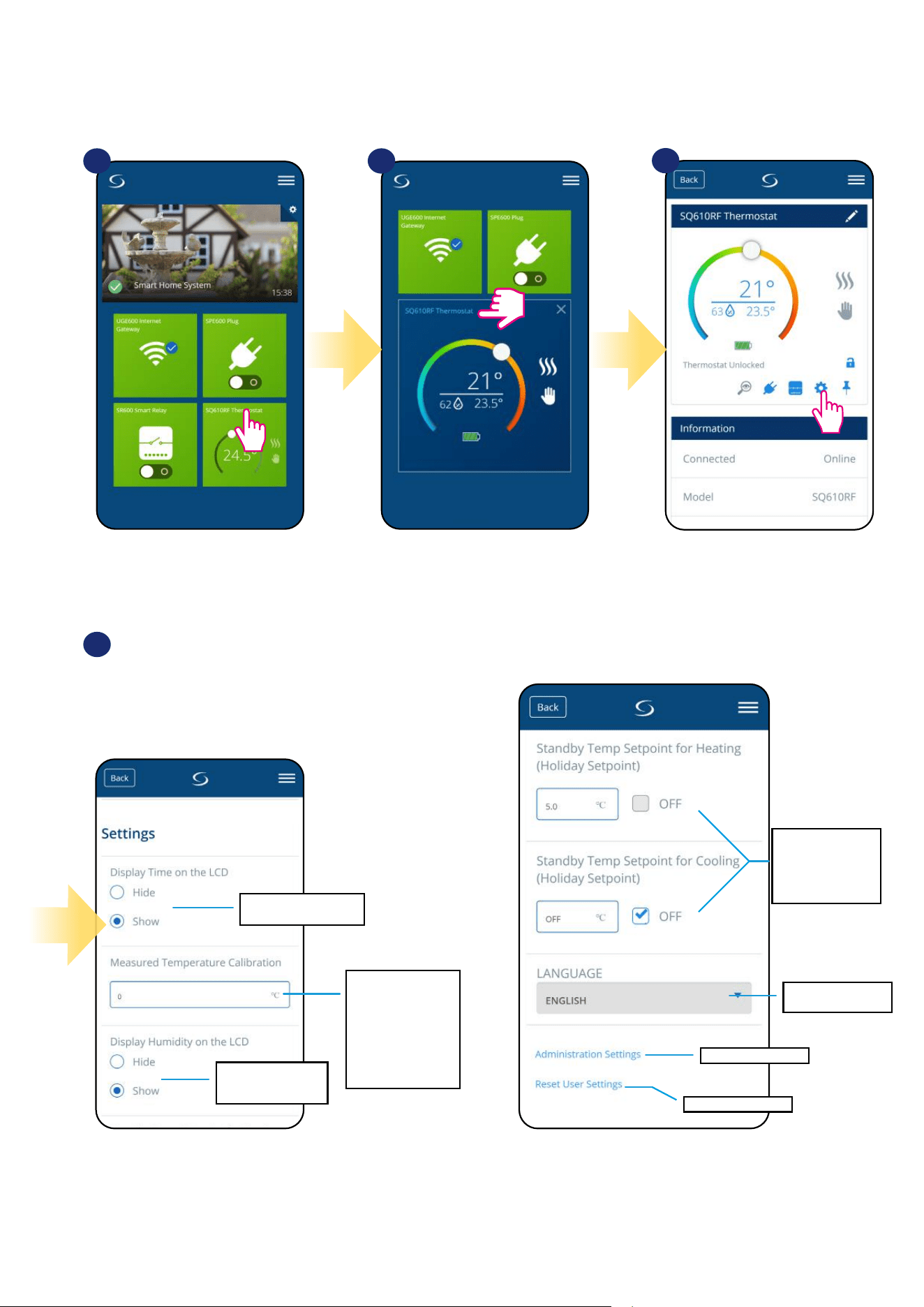
Show/hide time on the
thermostat’s LCD.
Thanks to this function
you can calibrate
temperature measu-
rements made by
thermostat from
-3,0 °C to 3,0 °C
intervals in 0,5 °C
steps.
Show/hide humidity
value on the
thermostat’s LCD.
Setpoint temperature
value for standby/
holiday mode
(separately for
heating and cooling).
Thermostat language
selection.
Advanced settings.
Reset user settings.
BASIC SETTINGS:
User settings of SQ610RF Quantum thermostat determine basic thermostat work modes (eg. thermostat calibration or standby temperature setpoint).
Please consider that service parameters change should be done by experienced users.
6.13 User settings (basic settings)
Select the thermostat in
the main app menu.
Select thermostat’s settings.
1 2
3
4
Scroll down to the settings section.
Press thermostat’s name.
40
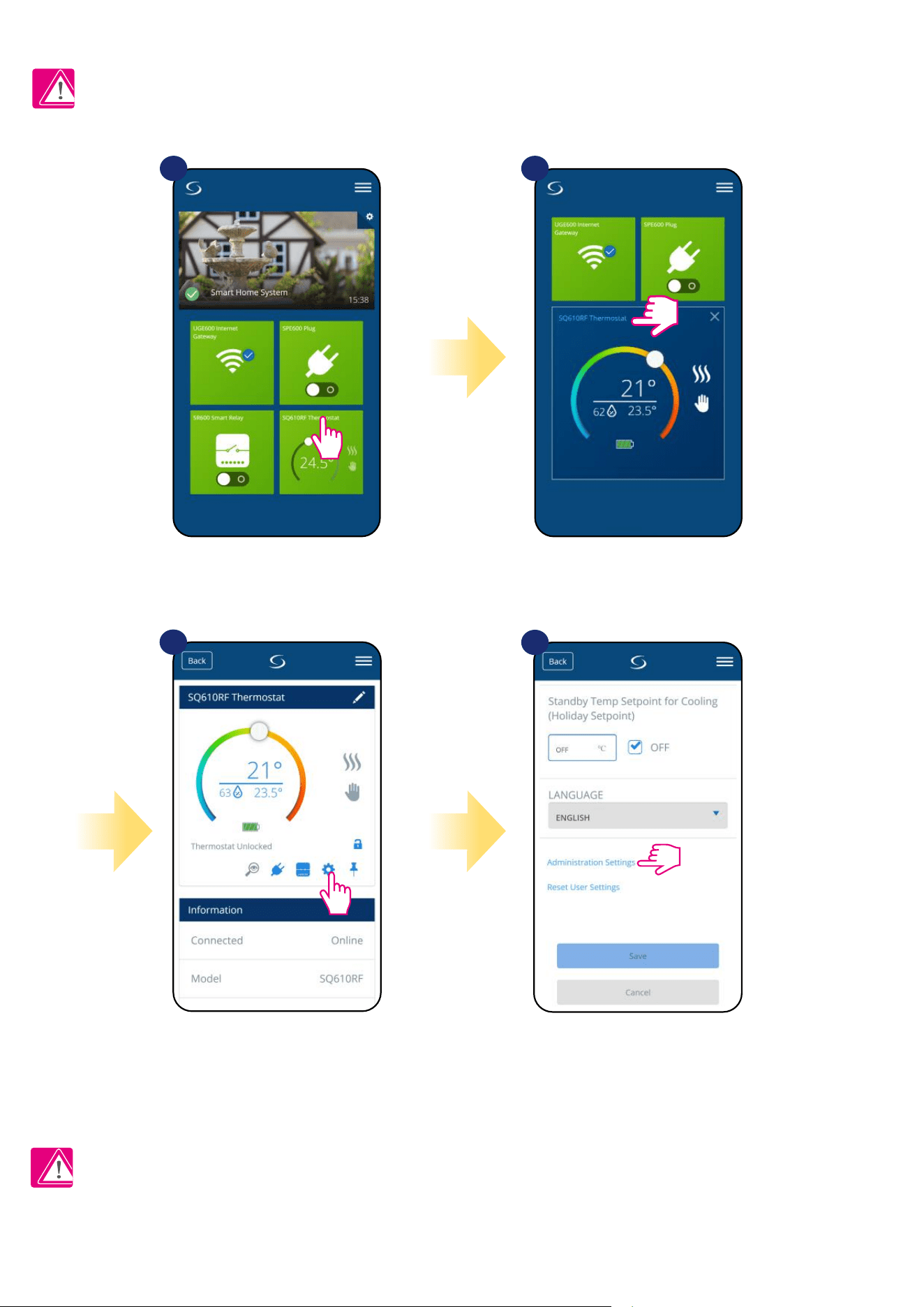
6.14 Admin Settings (Installer parameters)
PLEASE NOTE: Admin settings are mainly for qualied installers or knowledgeable users.
All service parameters with detailed admin settings are described on page 61!
Scroll down to enter
„Admin settings”.
Select the thermostat in
the main app menu.
Select thermostat’s settings.
1 2
3
4
Please Note:
Press thermostat’s name.
41
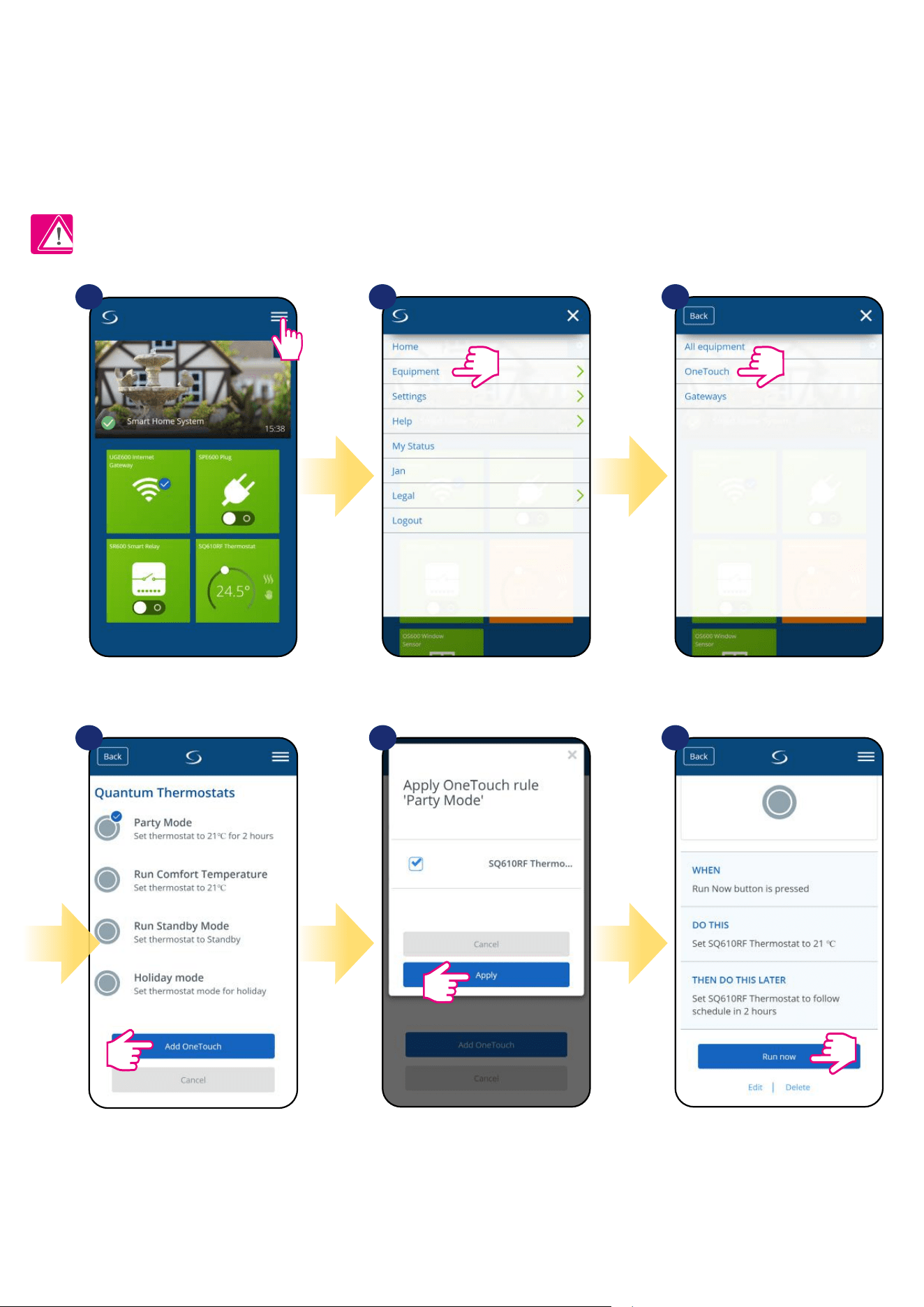
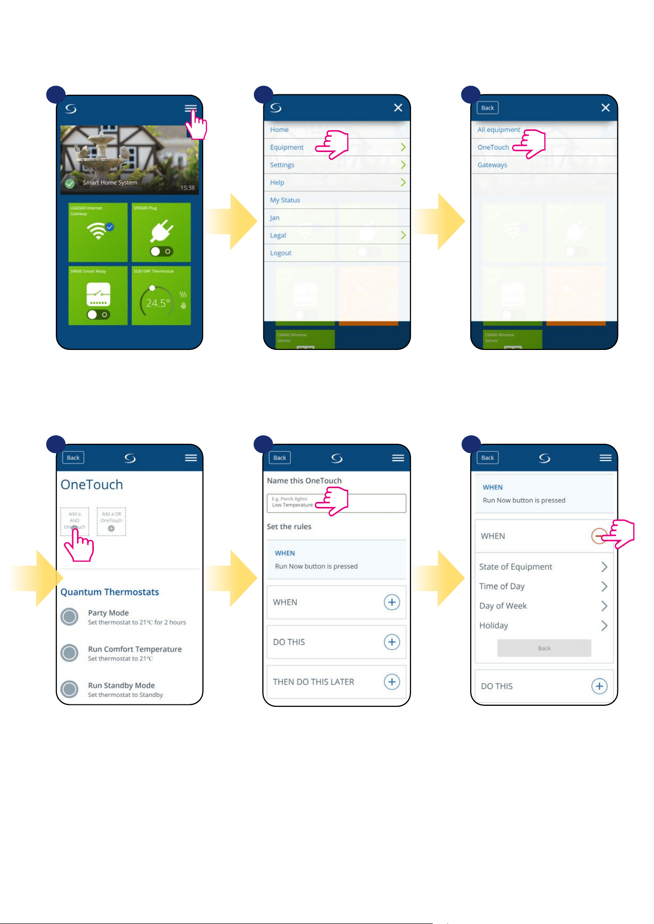
6.15 OneTouch rules (add/edit)
OneTouch - function that distinguish SALUS Smart Home system in terms of functionality. OneTouch rules are pre-congured set of actions dened
in the interface easy in use. You can switch it on or o anytime. OneTouch informs thermostat or other device how it has to work according to pre-set
settings. In application are 3 pre-dened OneTouch rules:
• Party Mode - set thermostat temperature to 21 °C for 2 hours
• Comfort Temperature - set thermostat temperature to 21°C
• Holiday Mode - set thermostat to Holiday Mode
To activate OneTouch rule please follow steps below (Party Mode activation as an example):
Party Mode has been activated.
You can check how it works by
pressing „Run now” button.
Choose „Party Mode” as a one
of the built-in OneTouch rules.
Click „Add OneTouch” to add it.
Select thermostats which you
want to congure with this rule.
Press „Apply” to conrm.
1 2 3
Open main menu in the app. Select equipment. Select OneTouch option.
4 5 6
42
1
4 5 6
2 3
Open main menu in the app. Select equipment. Select OneTouch option.
You can also create your own OneTouch rule. As an example we will create OneTouch rule which activates „send me a notication” action under
„temperature is below 10 °C” condition. Please look at the steps below how to set this OneTouch rule.
Press „Add a AND OneTouch” button. Enter OneTouch rule name. At this step choose condition which
have to be fullll in order to activate
the rule.
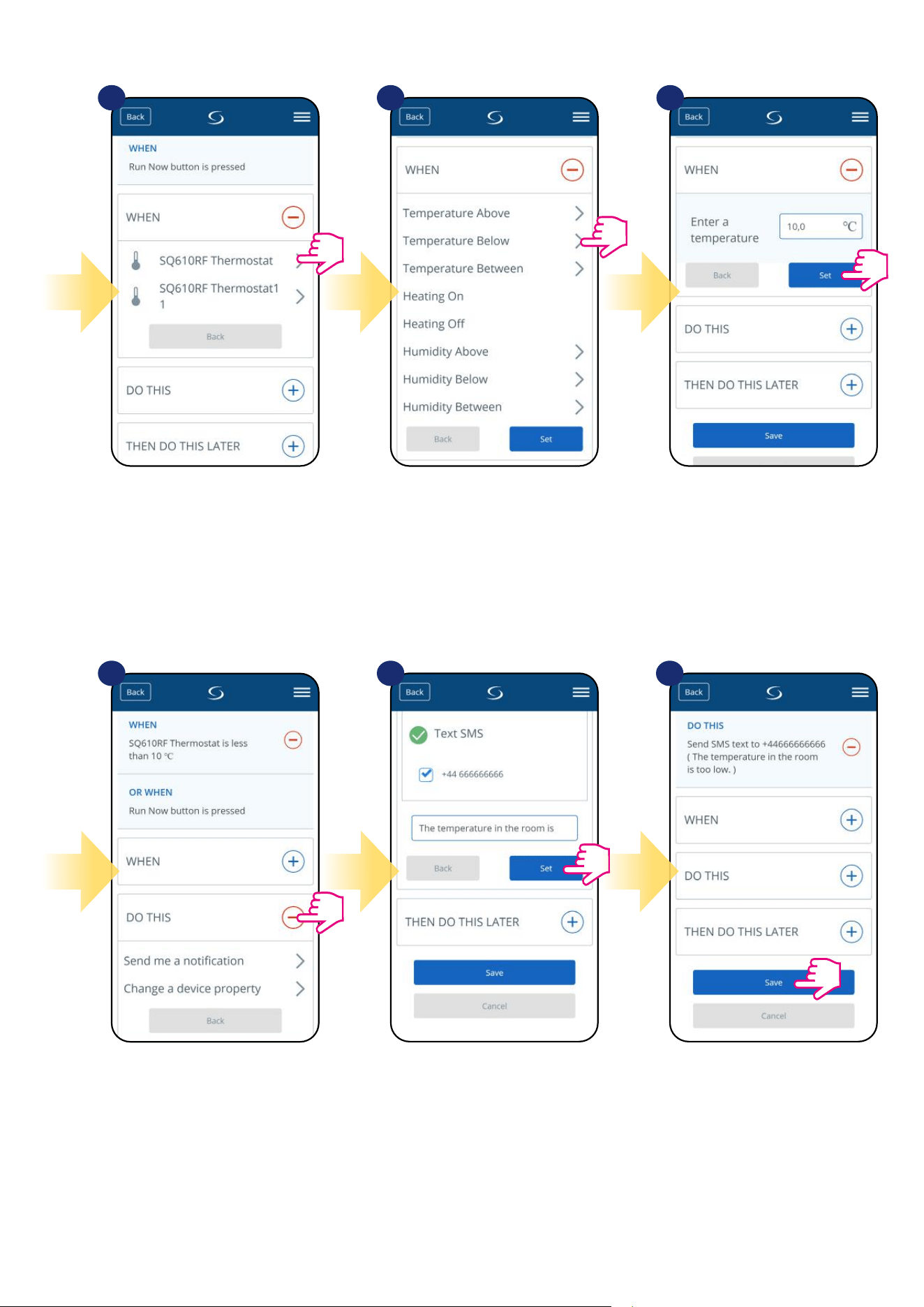
43
Select which thermostat you want to
link up with your OneTouch rule.
Select „DO THIS” option to create
OneTouch rule action.
Choose e-mail or SMS
notication and enter the message
content. Conrm by pressing „Set”
button.
To nish OneTouch rule creation
press „Save” button.
Choose the condition details for
your thermostat. In this case select
„Temperature Below” option.
Enter a temperature setpoint trigger
for your OneTouch rule. Press „Set”
button to conrm.
7
10 11 12
8 9
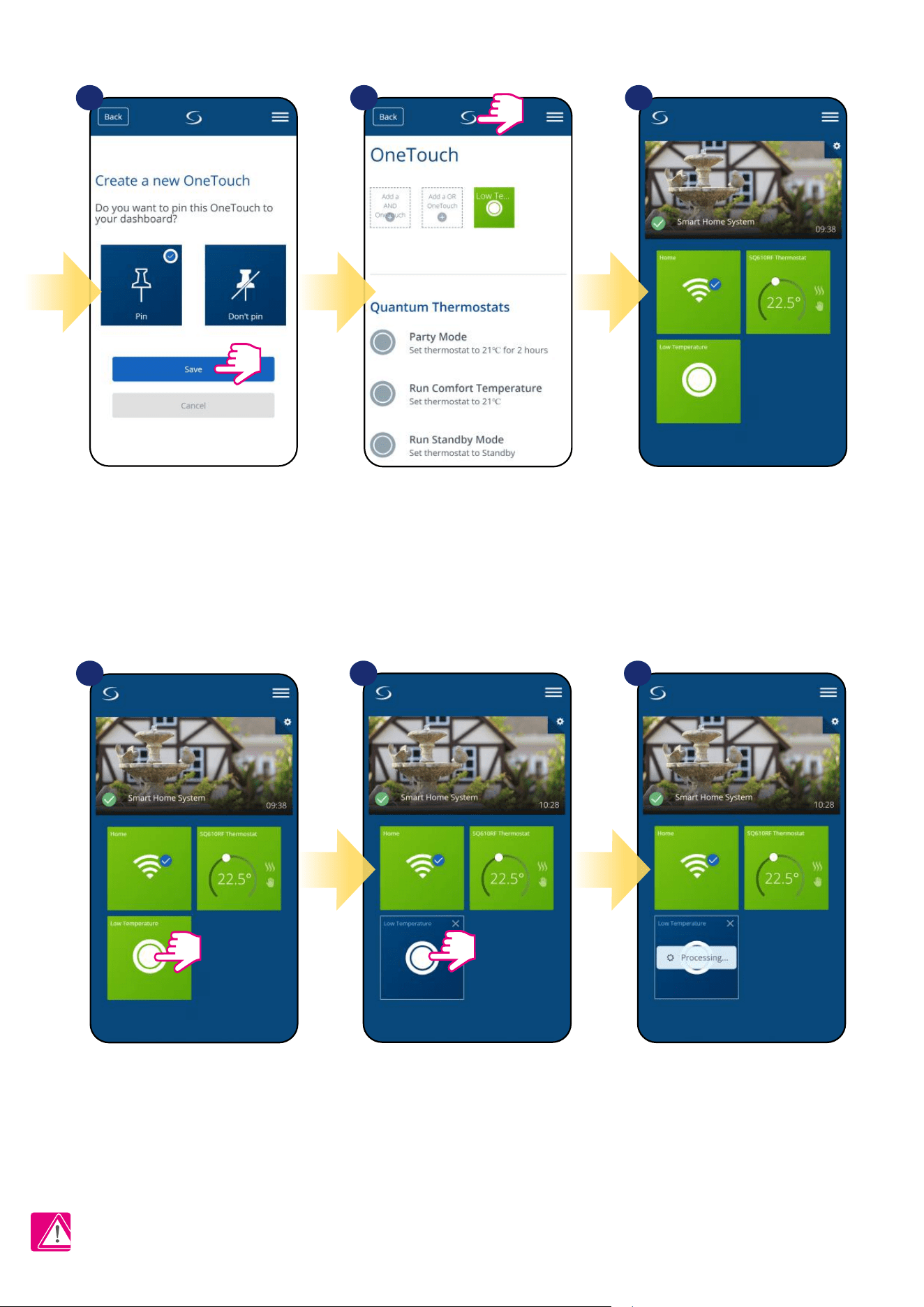
44
OneTouch rule is now activated. In this
example SMS message will be send to
the user.
...and press it’s button.To force OneTouch rule activation
select it tile...
As an option OneTouch rule tile can
be pinned to the dashboard.
Newly created OneTouch rule tile can be
found under OneTouch main menu...
... and on your dashboard.
13
1716 18
14 15
Please note: SMS notications will be send to the user only if they are activated in the OneTouch settings and UGE600 Universal Gateway is
connected to the Internet.
45
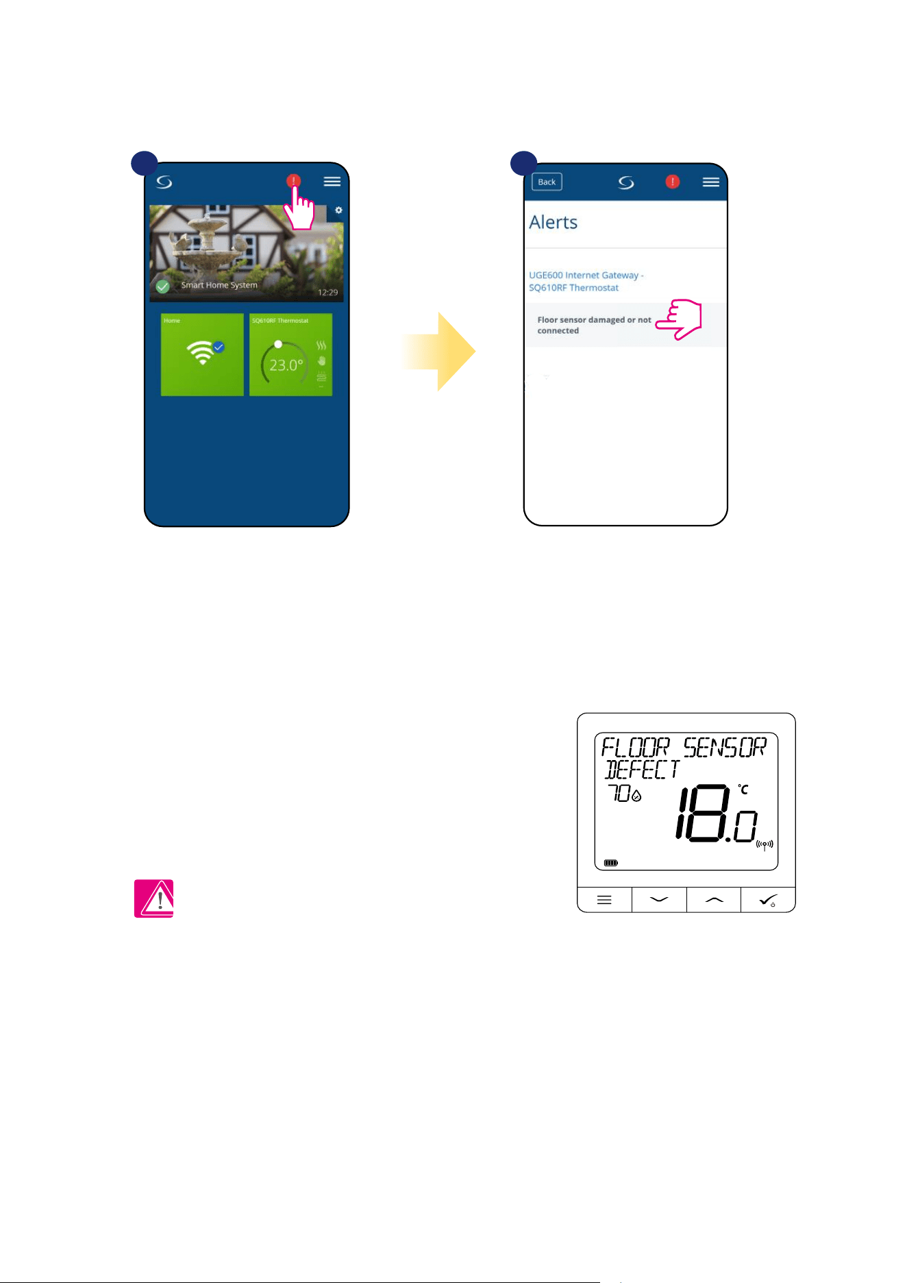
6.16 Error codes (exclamation mark in app)
If there is any error in the Smart Home system which relates to the devices performance or functionality then the Smart Home app will inform user about
it by a red exclamation mark in the upper menu. Please look at the example below:
Errors are visible also on the thermostat’s LCD display (like in the example below):
Floor Sensor Defect means that external sensor which is set as oor sensor
hasn’t been found or it has been damaged.
When problem has been solved (sensor change or re-connection in this case)
- exclamation mark will disappear in application and thermostat will stop
ashing error.
Full list of errors is in 11 chapter.
1 2
Press the exclamation mark button. All current errors are displayed.
46
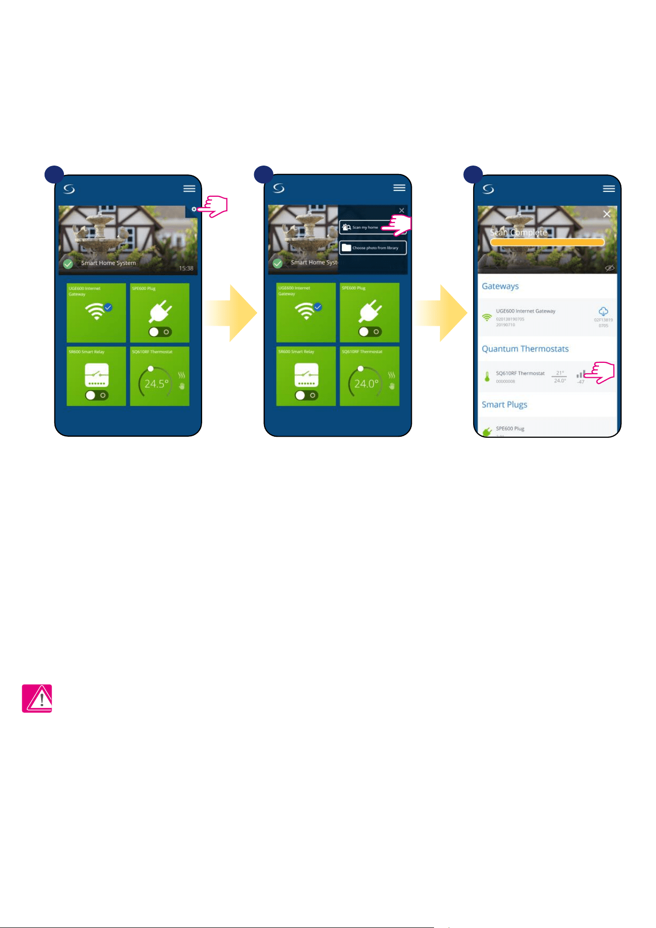
6.17 Wireless signal strength test
Each wireless device has a limited range. Beyond distance there are many more elements which could aect on. For example - concrete walls, other
wireless network interferences, wooden walls, reinforced concrete ceilings, metal construction elements, pillars, aluminium foil for underoor heating
etc.
Smart Home system has built-in function which allows to check wireless signal quality. If you want to check your system connectivity
and signal’s strength please follow steps below:
Signal quality is expressed in decibel units (db). Compare your value with scale below:
-50db to 0db - very good quality signal
-75db to -50db - good quality signal
-85db to -75db - low quality signal
-95db to -85db - bad quality signal, make wireless connection nearly impossible
PLEASE NOTE: Every Smart Home system device which is powered 230VAC is also working as a signal repeater of ZigBee network. If system is
based on battery devices there could be a need to use repeaters like Salus RE600, Salus RE10RF or any other device of Salus Smart Home series
which is powered by 230V AC.
Press the gear icon in upper right
corner of the background image.
Select „Scan my home” option. Here you can check wireless
signal quality of given devices.
1 2 3
47
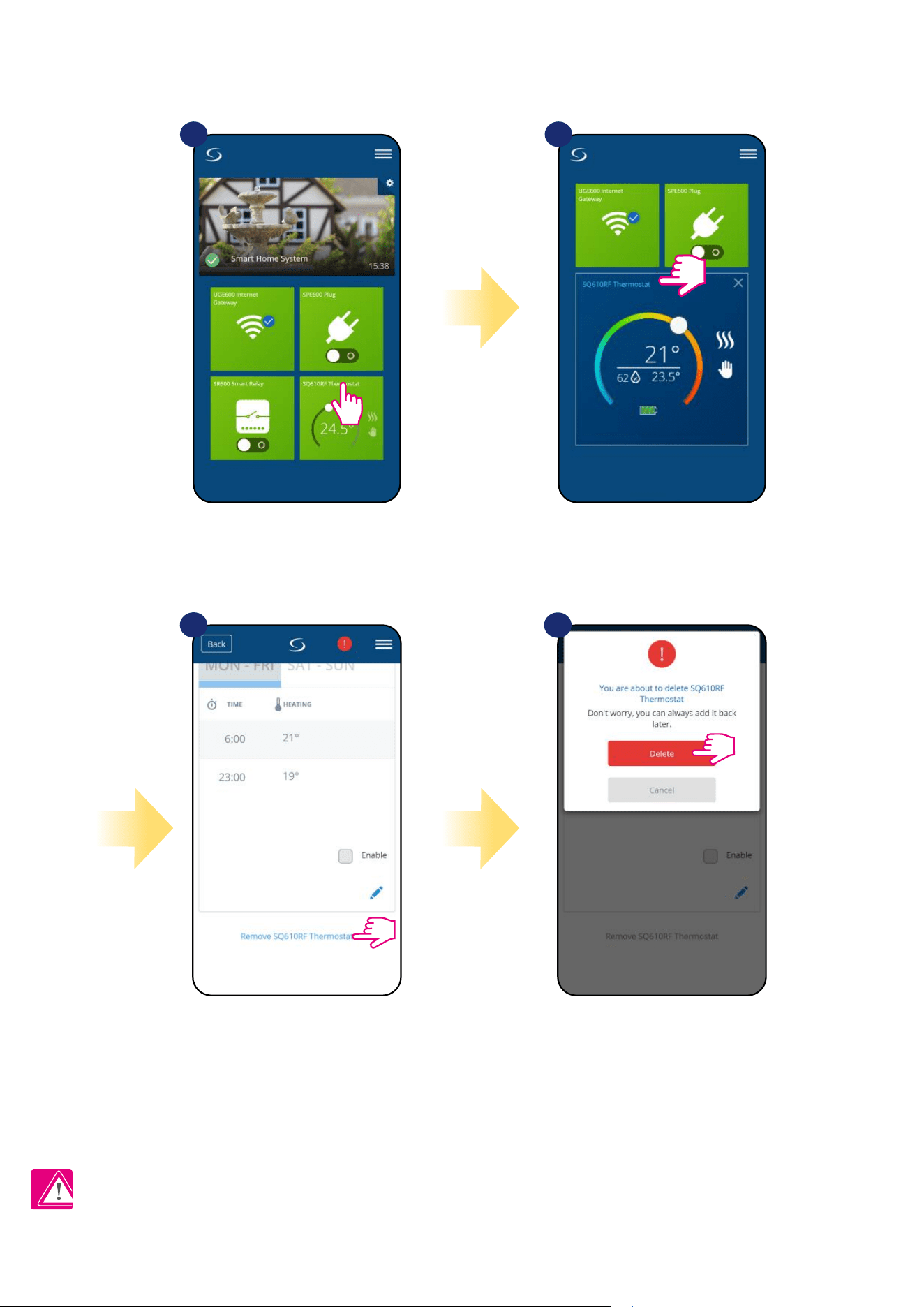
6.18 Factory reset (removing thermostat from the app and ZigBee network)
To make thermostat factory reset and remove it from the ZigBee network please follow steps below:
NOTE: As a conrmation of correct removing process from the network we can’t see our thermostat in „My Equipment” list.
At the very bottom of
thermostat’s menu choose
„Remove” option.
Press „Delete” button to remove
your thermostat from the app
and conrm factory reset.
1 2
Select the thermostat in
the main app menu.
3
4
Press thermostat’s name.
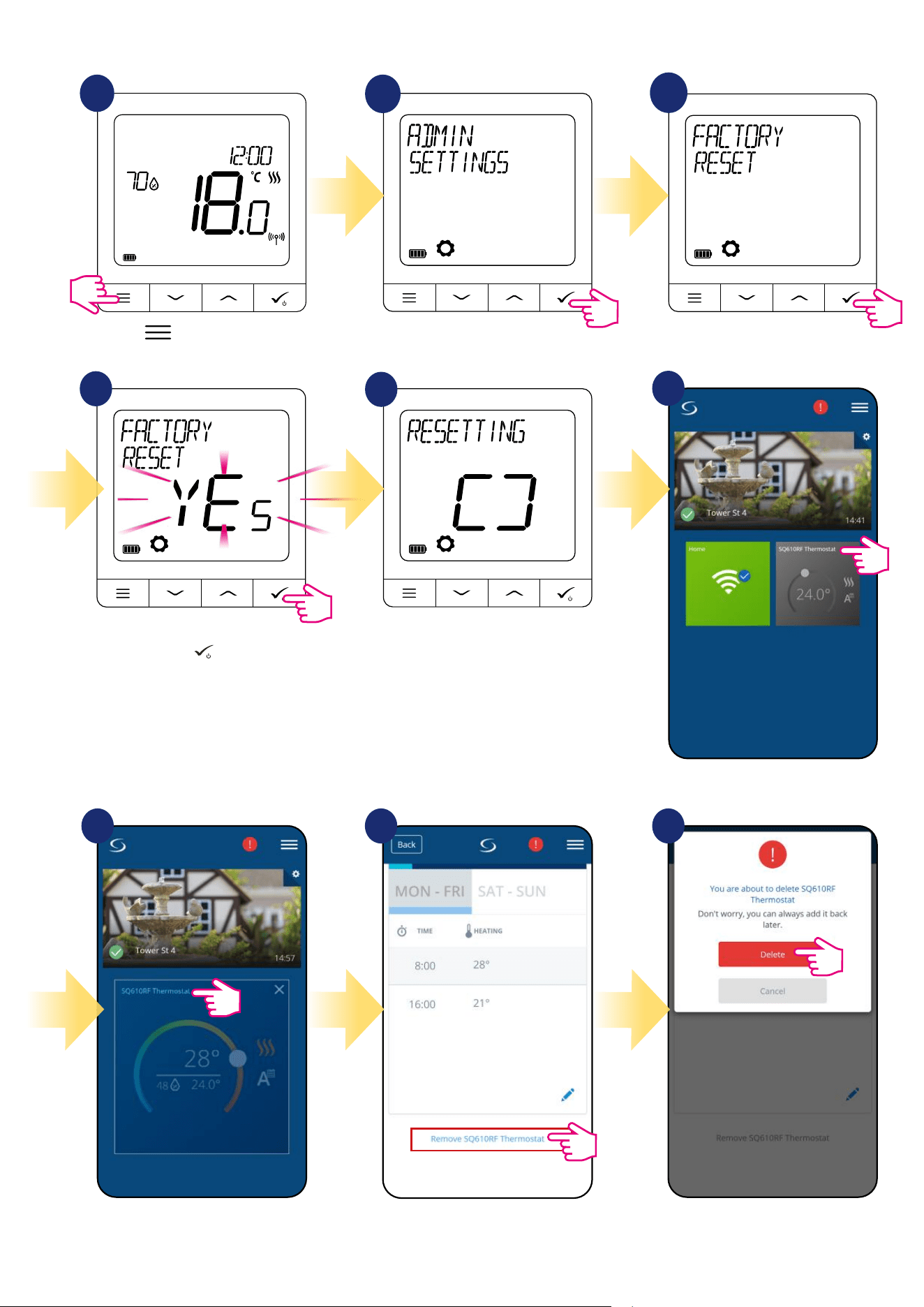
48
At the very bottom of thermostat’s menu
choose „Remove” option.
Press „Delete” button to remove your
thermostat from the app and conrm factory
reset.
Select the thermostat in
the main app menu.
You can also do factory reset from the thermostat directly. It will also remove your thermostat from the Zigbee network but you still will be able to see
thermostat’s tile. After factory reset thermostat tile will change to dark grey colour.
1
2
3
4
5
Wait few moments to nish factory
reset procedure. Now you can
remove thermostat from the app.
Go to the Admin Settings.
Press button to enter the
main menu.
Choose „Factory Reset” option.
Select YES and conrm choice by
pressing
button
.
6
7 8 9
Press thermostat’s name.
49
7. Installation in OFFLINE MODE without SALUS SmartHome application
7.1 General informations
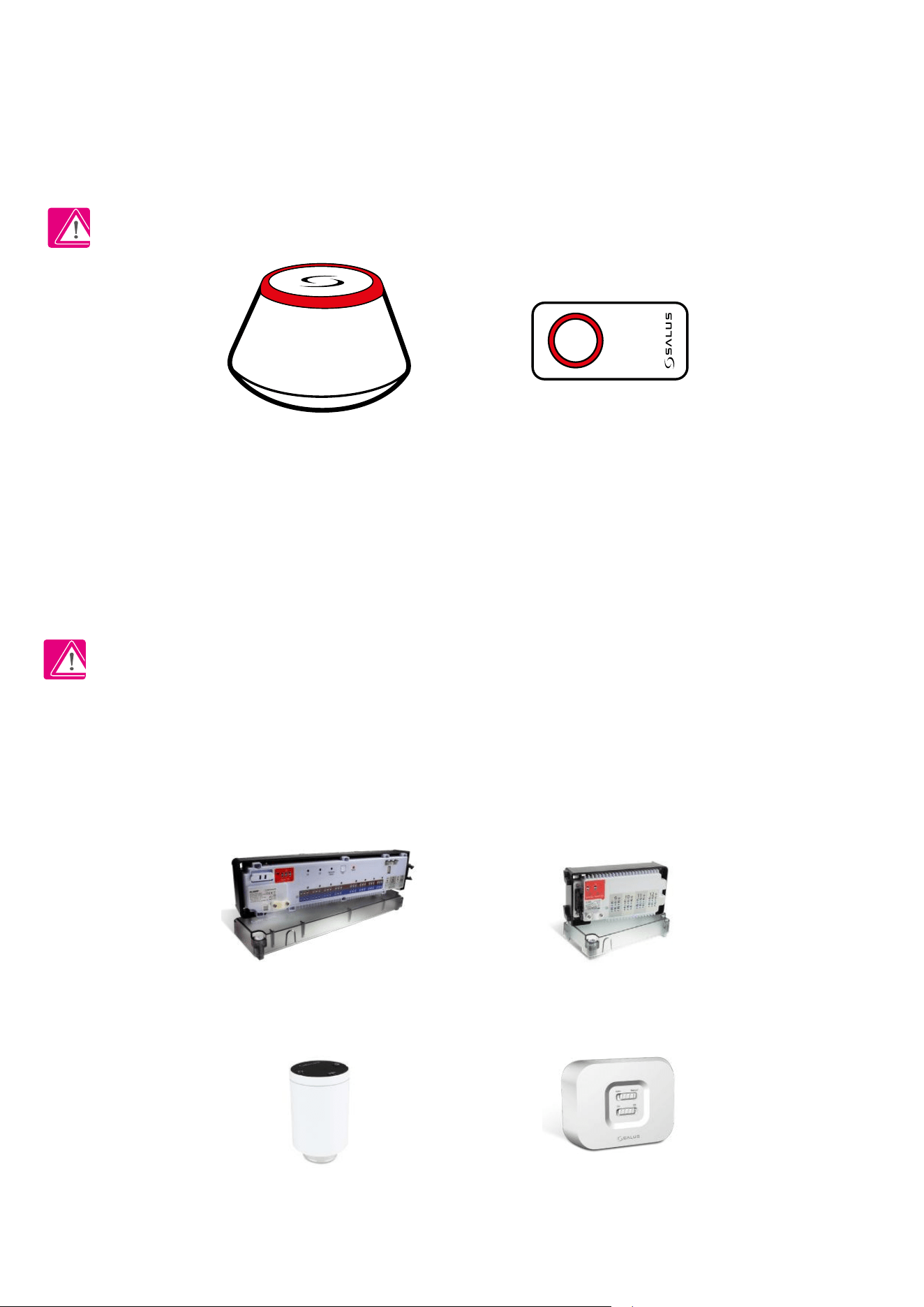
In OFFLINE mode (without application), you can use the UGE600 Universal Gateway or CO10RF coordinator to congure the system. Please
note that you cannot use both devices at the same time. Before installing the system you have to decide:
- to create a network using the UGE600 Universal Gateway (you can connect it to the Internet in the future)
- to create a network using the CO10RF coordinator (you can’t connect it to the Internet)
REMEMBER! The UGE600 Universal Gateway and CO10RF coordinator are two dierent devices.
Each device creates and operates it’s own network.
Universal Gateway - - CO10RF Coordinator
Please note! If your system has been installed in the OFFLINE mode using the UGE600 Universal Gateway and then
connected to the Internet, all devices should be found in the SALUS Smart Home application (using „Scan for equipment”
button). All devices found in the application don’t need to be recongured, because all settings are automatically copied
from the gateway.
Please note! If your system was created using the CO10RF coordinator and you would like to control the devices via
the Internet, then all devices should be reinstalled using the UGE600 Universal Gateway.
CO10RF Coordinator
You can use standard ZigBee network coordinator to install and use your
devices.
NOTE: CO10RF Coordinator is included in the set with the KL08RF
Control Box.
Universal Gateway is
NOT CONNECTED TO THE INTERNET
You can use your devices locally without the Smart Home App. Gateway
works in this mode as standard ZigBee coordinator.
KL08RF - Wiring Centre for 8-zone
underoor heating (UFH).
+ expand KL04RF
TRV
(Thermostatic Radiator Valve)
- with wireless communication.
RX10RF
receiver
50
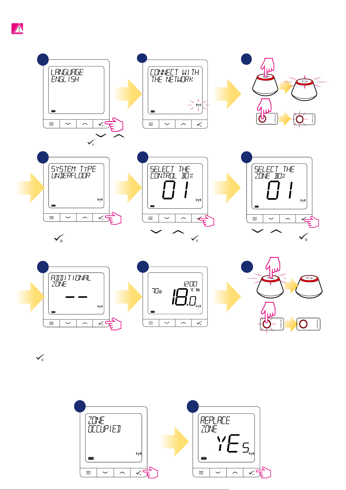
7.2 Pairing with underoor heating wiring centre (KL08RF/Control Box)
1
3
Open the ZigBee network
4
7
5
6
Select system type: UNDERFLOOR,
press button to conrm.
Using and buttons select the
Control Box number. Press button to
conrm.
Use or buttons to select
the zone number and press
button to conrm.
8
You can pair your thermostat with
more than one zone. Select additional
zones or nish the pairing process by
button.
OR
5 sec.
5 sec.
9
Close the ZigBee network
OR
3
3
5 sec.
5 sec.
REPLACE ZONE:
If user during pairing process will choose already occupied zone then thermostat will display „ZONE OCCUPIED” message. Occupied zone can be replaced
by other thermostat. It will remove current thermostat assigned to that zone. Please look at the steps below:
1
2
Select your language using or
buttons and conrm by
button.
When thermostat is succesfully
paired main screen will be
displayed.
2
PLEASE NOTE!
For easier installation, please make sure you have already added underoor heating wiring centre (KL08RF/Control Box) to your ZigBee network (please
refer to the underoor heating wiring centre manual instruction).
Now thermostat is looking for the
signal from the coordinator...
51
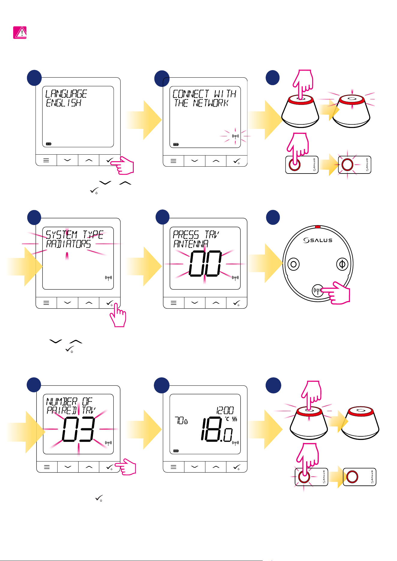
7.3 Pairing with wireless TRV radiator head
3
6
Open the ZigBee network
Select system type “RADIATORS”
using or buttons and
conrm it by button.
Hold antenna button for 10 sec. on all TRV’s
which you want to pair with your
thermostat.
On the LCD you will see the number of paired TRV’s.
Once all TRV’s are paired - press button to nish
the pairing process.
OR
5 sec.
5 sec.
10 sec
98
Close the ZigBee network
OR
5 sec.
5 sec.
You can pair up to 6 TRV’s with 1 thermostat.
All TRV’s have to be within the same room
with thermostat.
3
3
Select your language using or
buttons and conrm by
button.
2
5
4
7
1
PLEASE NOTE!
For easier installation, please make sure you have already added wireless TRV radiator heads to your ZigBee network (please refer to the wireless TRV
radiator head manual instruction).
When thermostat is succesfully
paired main screen will be
displayed.
Now thermostat is looking for the
signal from the coordinator...
52
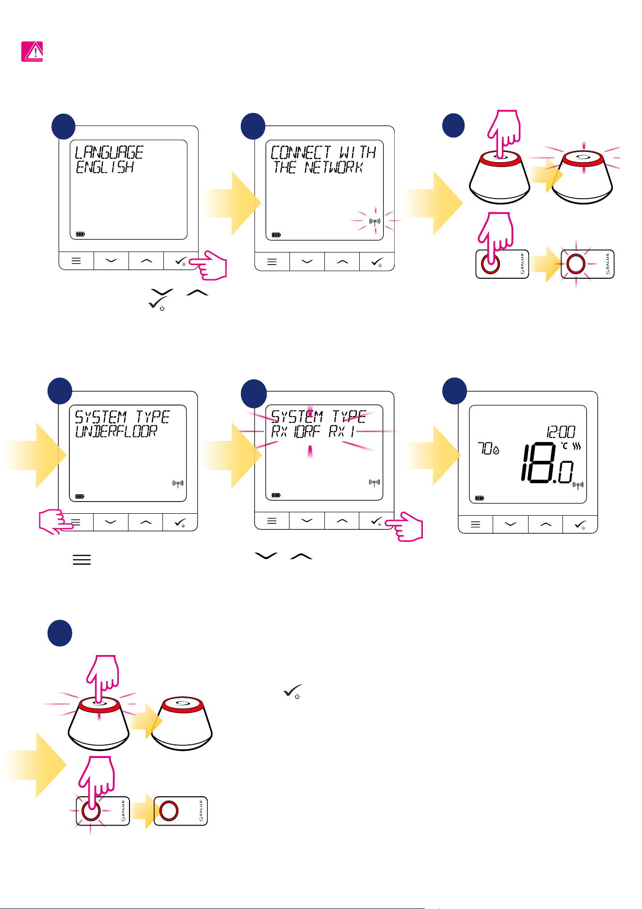
7.4 Pairing with RX10RF receiver
3
Open the ZigBee network
OR
5 sec.
5 sec.
2
4
7
Press button for 3 seconds to expand
“SYSTEM TYPE” menu.
5
Use or buttons to:
- choose pairing with the RX10RF receiver in
the „RX1” conguration, if the receiver is set as
RX1 (receiver responds to the heating signal
from any thermostat),
- choose pairing with the RX10RF receiver in
the „RX2” conguration, if the receiver is set as
RX2 (receiver responds to the heating signal
from only one thermostat).
Conrm by
button
6
Select your language by or
buttons and conrm by
button.
Now thermostat is looking for the
signal from the coordinator...
After all you will see the main
thermostat’s display.
1
PLEASE NOTE!
For easier installation, please make sure you have already added RX10RF receiver to your ZigBee network (please refer to the RX10RF receiver manual
instruction).
Close the ZigBee network
OR
5 sec.
5 sec.
3
3
53
8. OPERATING in OFFLINE MODE
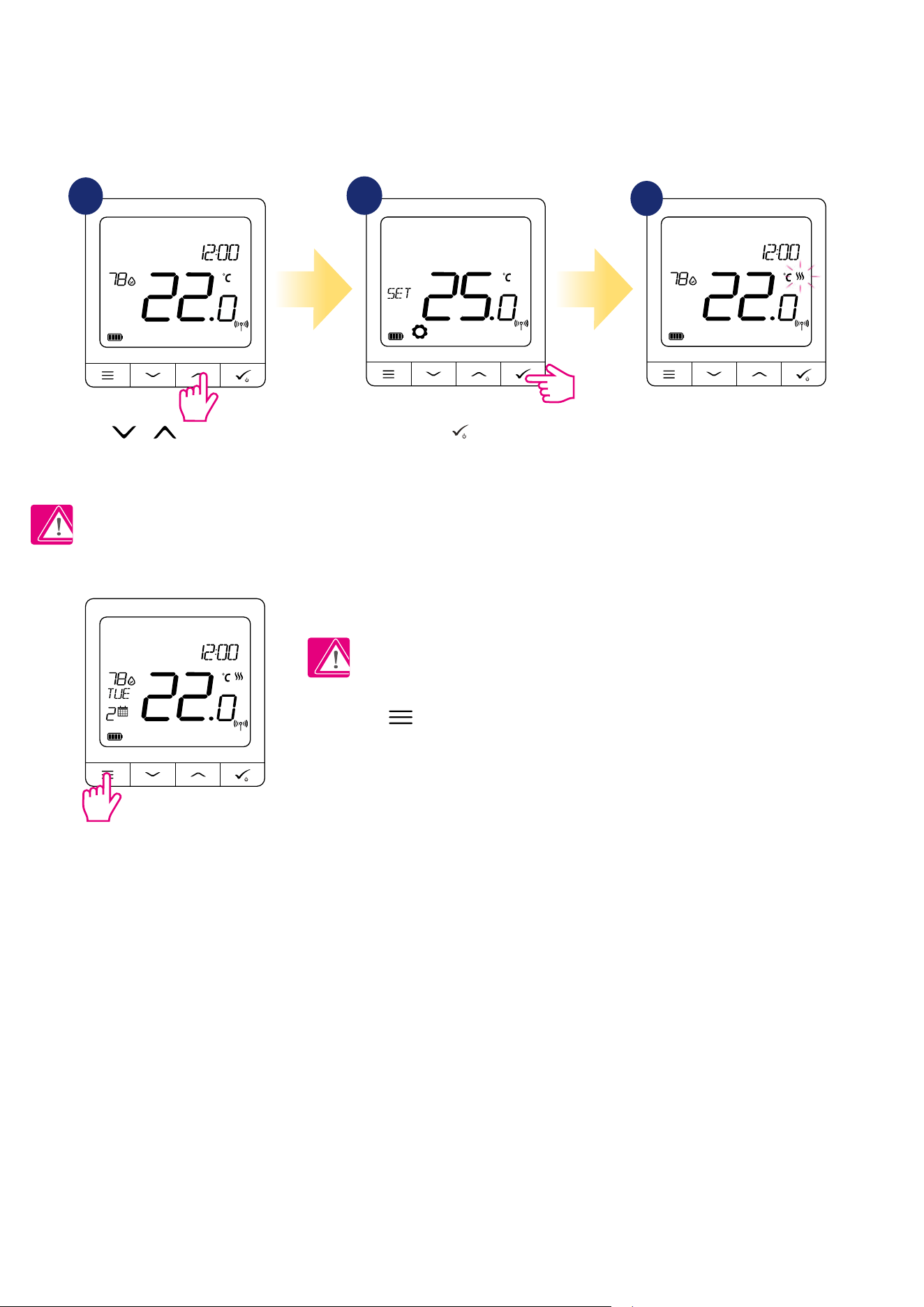
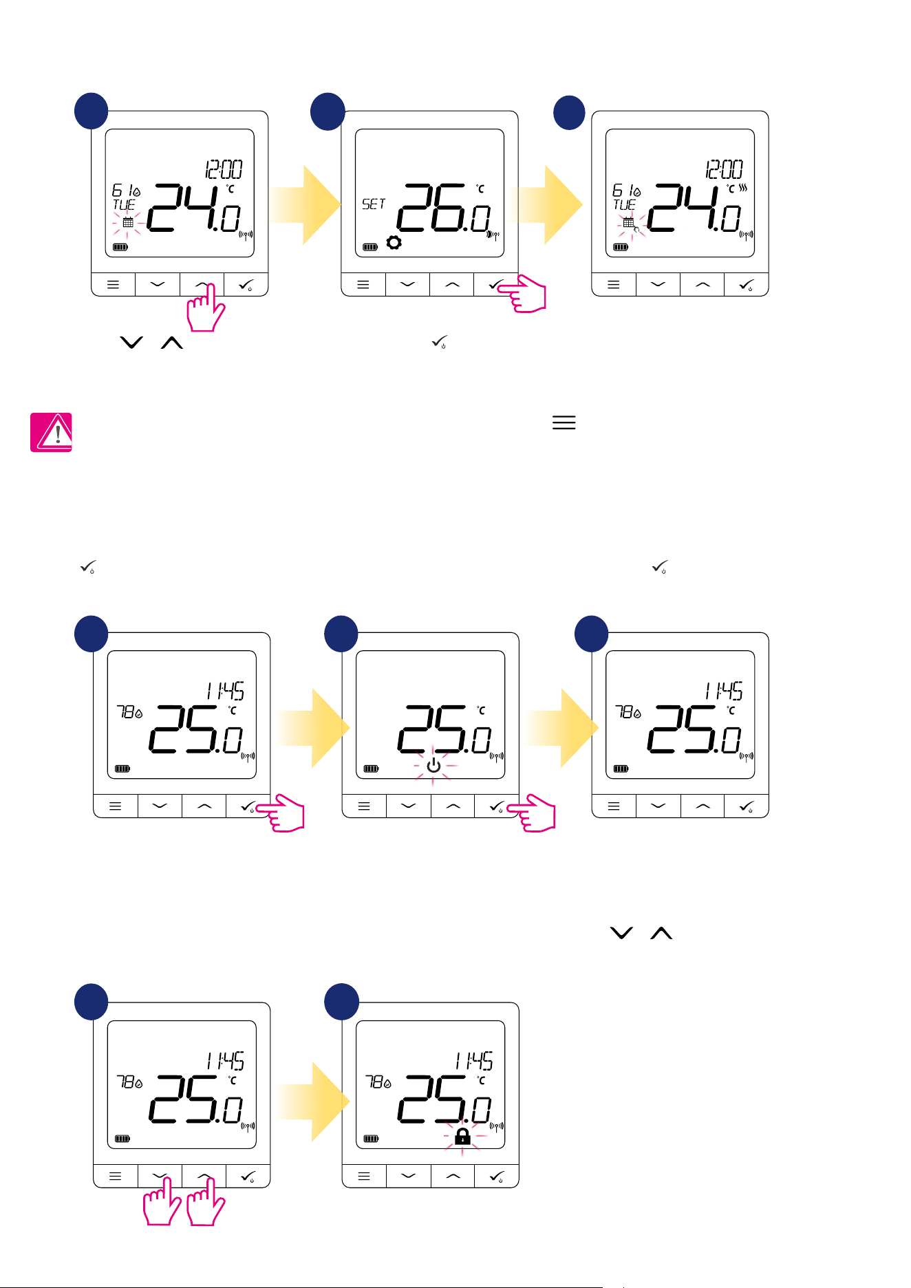
8.1 Setpoint temperature change (manual mode)
1
2
3
SQ610RF Quantum thermostat is in manual mode by default. To change setpoint temperature please look at the steps below.
Use or buttons to set
temperature.
Conrm by button. Thermostat will go back to the
main screen.
PLEASE NOTE: If you want to switch between schedule mode and manual mode you
have to press button for 3 seconds on the main screen.
Active HEATING (or COOLING) is indicated by animating ame (heating) or snowake (cooling).
54
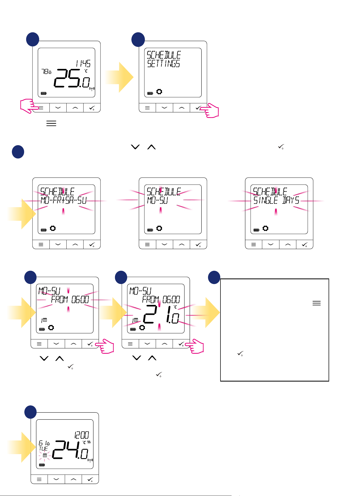
8.2 Schedule mode
To program schedule in oine mode please follow steps below:
There are 3 possible schedule variants. Use or buttons to select schedule variant and conrm by button:
Separate schedule for WORKING DAYS
and separate schedule for WEEKENDS.
One schedule for
WHOLE WEEK
Seven separate schedules for
SINGLE DAYS
1
2
3
Press button to enter the
main menu.
Enter into the schedule settings.
Thermostat will move to the next program
(next time period). If you made a mistake, you
can go back to the previous step using
button (changes will not be saved). Repeat
steps 4 and 5 for the next time periods in
the schedule. No time --:-- on the display
means given program is skipped. There are
6 programs/time perdiods in the schedule.
Hold button for 3 seconds to save and exit
schedule editing.
After setting the schedule thermostat is working in schedule mode. You can see calendar icon on the display:
Schedule programming example for the WHOLE WEEK variant:
Use or buttons to set
time. Conrm by button.
Use or buttons to set
temperature setpoint.
Conrm by button.
4
5
6
7
55
3 sec.
3 sec.
8.4 Standby mode
STANDBY mode is a special setpoint temperature which can be activated/deactivated in any time. It can work like a frost protection or overheating
protection when needed. When standby mode is activated the clock continues running, as well as the temperature sampling. To enter STANDBY mode
hold the button for 3 seconds on your thermostat. You can always turn o STANDBY mode by holding the button for 3 seconds again.
3 sec.
1 2
3 sec.
3
8.5 Key lock function
To LOCK/UNLOCK SQ610RF Quantum thermostat keys in OFFLINE MODE you have to press and hold + buttons for 3 SECONDS. When
thermostat is locked you will see padlock icon on the display. When thermostat is unlocked padlock icon is not visible.
1
2
8.3 Temporary override mode
When thermostat is running schedule mode we can temporarily override it by setting new setpoint temperature.
Use or buttons to
change setpoint temperature.
Conrm by button.
Calendar with hand icon means that
schedule has been overwritten until next
schedule program.
1
2
3
PLEASE NOTE: To cancel temporary override mode and go back to the schedule hold button for 3 seconds. The calendar
icon indicates that thermostat went back to schedule mode.
56
In OFFLINE mode user has got acces to the all thermostat settings.
To open MAIN MENU press button on
the main screen.
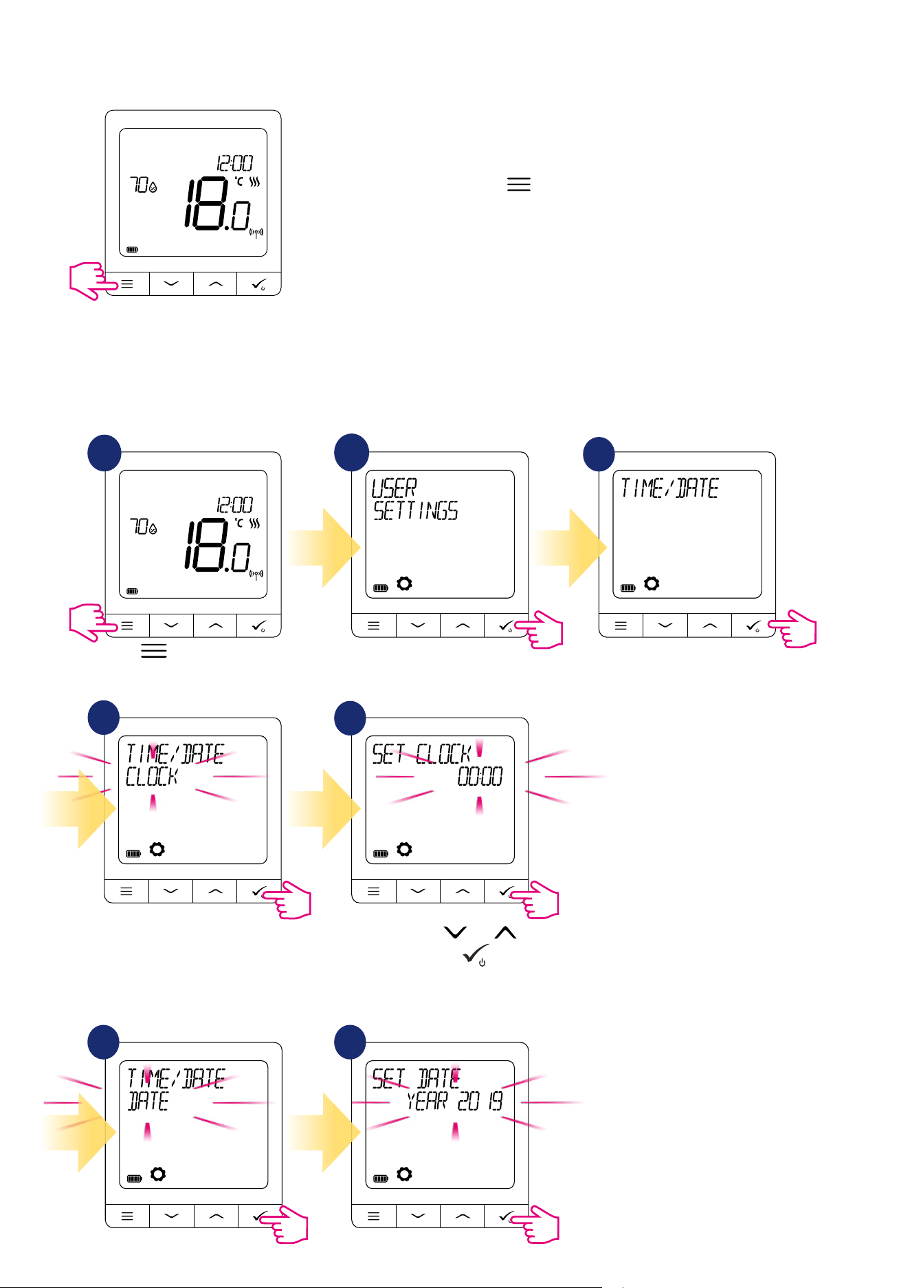
8.6 User settings (basic settings)
8.6.1 Time/Date
Time/date change or edit can be done only in Oine mode. In Online Mode thermostat will synchronise
current time and date based on information taken from the Internet. To set time/date follow steps below:
1
Set your time using and buttons.
Conrm your choice by
button.
2
3
4
5
DATE settings will automatically appear after clock setup:
Press button to enter the
main menu.
Go to the user settings. Choose time/date option.
Go to clock settings.
6 7
57
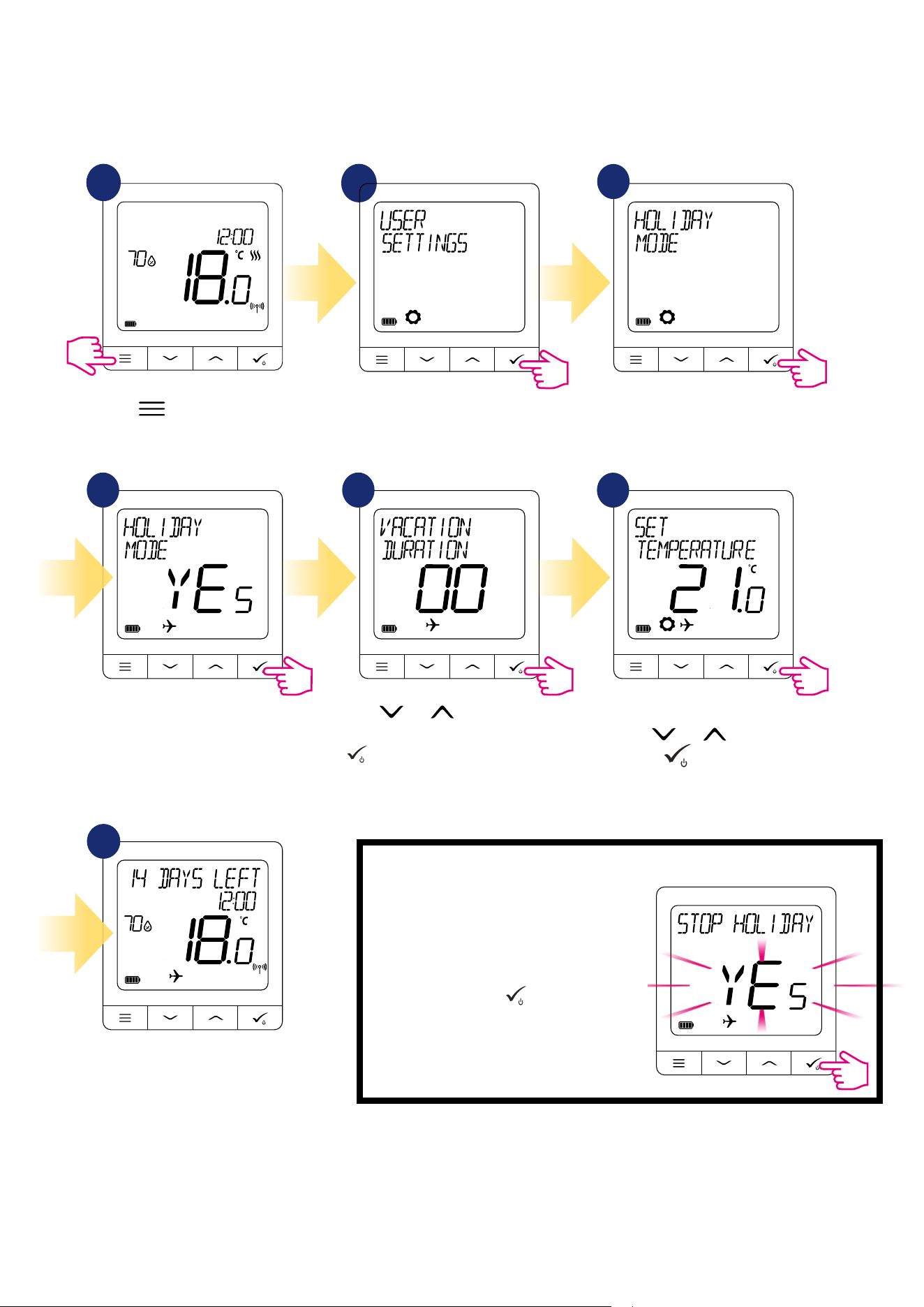
1
2
Using and buttons set
vacation time (in days). Conrm by
button.
Set temperature setpoint for holiday
mode by and buttons.
Conrm by button.
HOLIDAY MODE is ON. On the top of the
screen you can see days left to the end.
Also „plane” icon indicator informs that
HOLIDAY MODE is running.
To TURN OFF HOLIDAY MODE:
Press any button when HOLIDAY MODE is
active. To turn o HOLIDAY MODE choose
YES and conrm it by button.
3
4 5
6
7
8.6.2 Holiday mode
Holiday mode is a special program temperature setpoint which thermostat will maintain for specied days.
How to set HOLIDAY MODE:
Go to the user settings.
Press button to enter the
main menu.
Choose holiday mode option.
Select „Yes” to SET ON the
holiday mode.
58
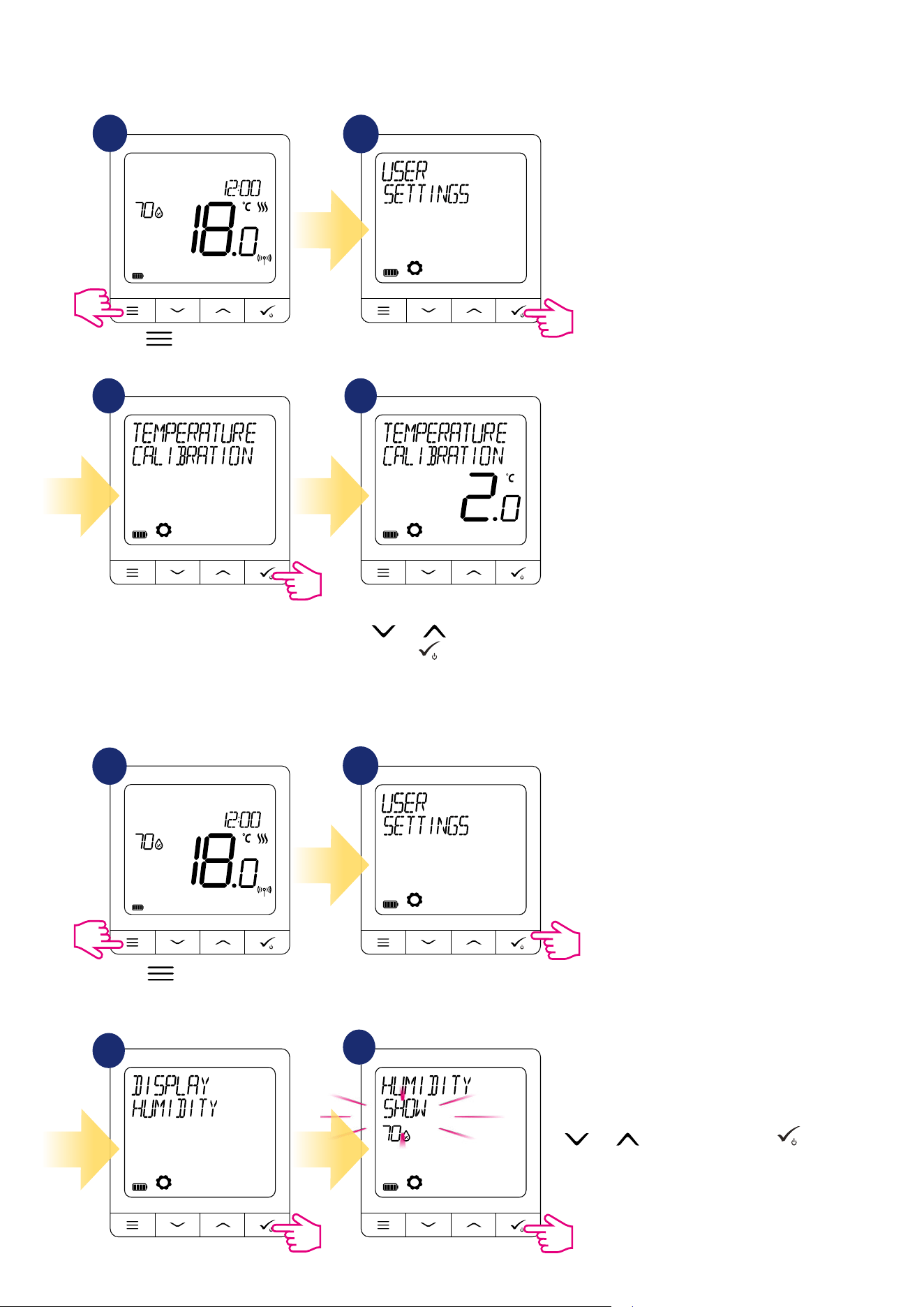
8.6.3 Thermostat calibration
Thermostat calibration is a function which allows user to recalibrate internal thermostat’s temperature sensor by a given number of degrees (in the range
from -3,5 °C to 3,5 °C). To calibrate thermostat’s temperature sensor please follow steps below:
1
2
Set temperature calibration value
by and buttons and
conrm by button.
3
4
8.6.4 Display humidity
SQ610RF thermostat has built-in hygrometer (humidity sensor). Humidity value can be displayed or hidden depending on the user’s needs. To show/hide
humidity value please follow steps below:
1
2
Choose SHOW to see humidity indication
on the main screen or HIDE to not to. Use
and buttons and conrm by
button.
3
4
Go to the user settings.
Press button to enter the
main menu.
Choose temperature calibration
option.
Go to the user settings.
Press button to enter the
main menu.
Choose display humidity option.
59
Set temperature setpoint by
or buttons. Conrm by
button.
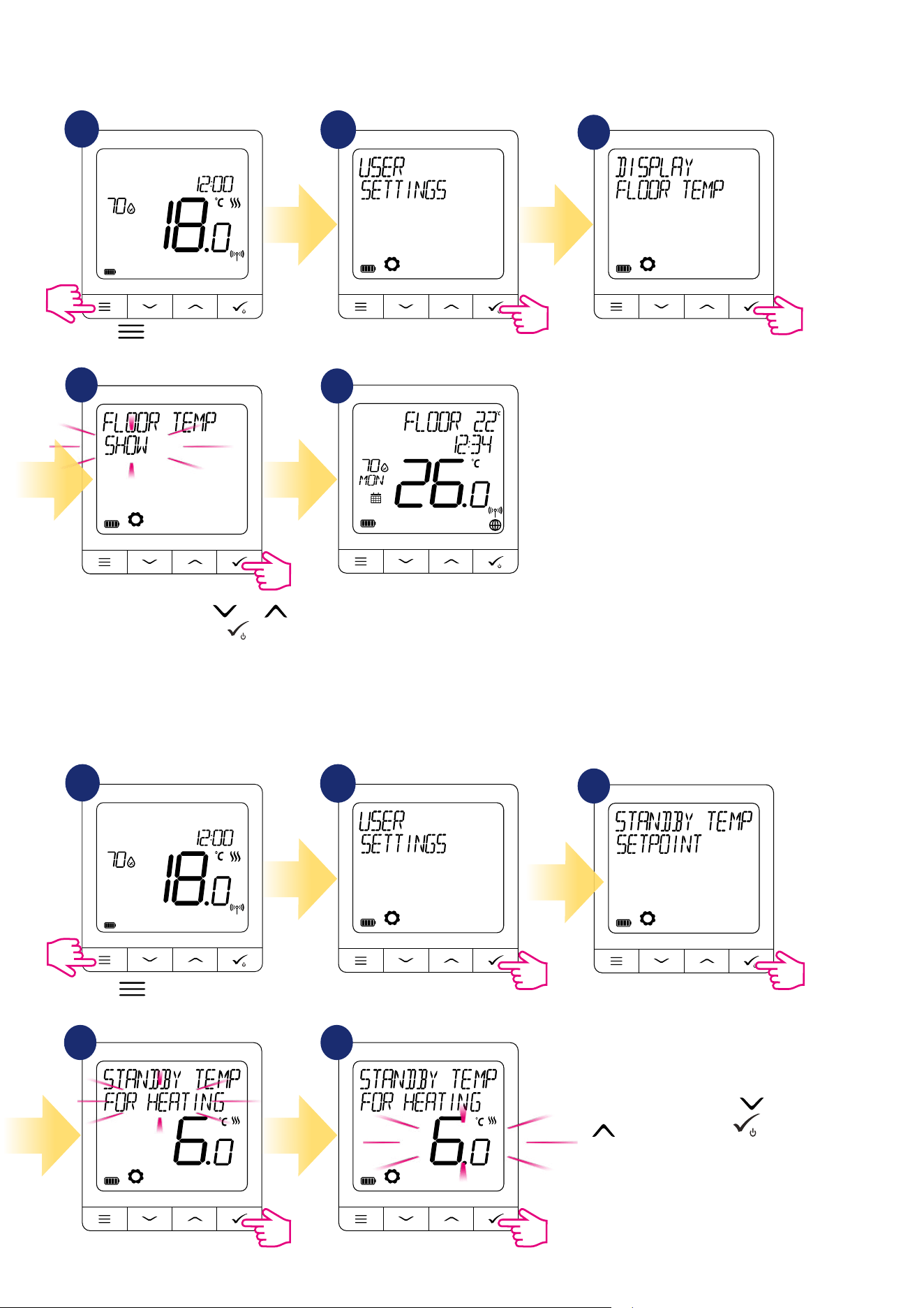
8.6.5 Display oor temp
Display oor temperature is a function which is available only when thermostat works with external oor temperature sensor. To show/hide oor
temperature value please follow steps below:
1
2
3
4
5
Floor temperature value is
displayed with one degree
accuracy.
8.6.6 Standby temp setpoint
There are two standby temperature setpoints - for heating and for cooling mode. Standby setpoint range for heating mode is from 5 ° C to 35 ° C. Standby
setpoint range for cooling mode is from 5 ° C to 40 ° C. To set it on please follow steps below:
NOTE: If paired with TRV radiator heads or RX10RF receiver, then standby for cooling is not available.
1
2
3
4 5
Go to the user settings.
Press button to enter the
main menu.
Choose display oor temp option.
Choose standby temp setpoint option.
Select for heating or cooling option.
Select SHOW or HIDE using and
buttons. Conrm selection by button.
Go to the user settings.
Press button to enter the
main menu.
60
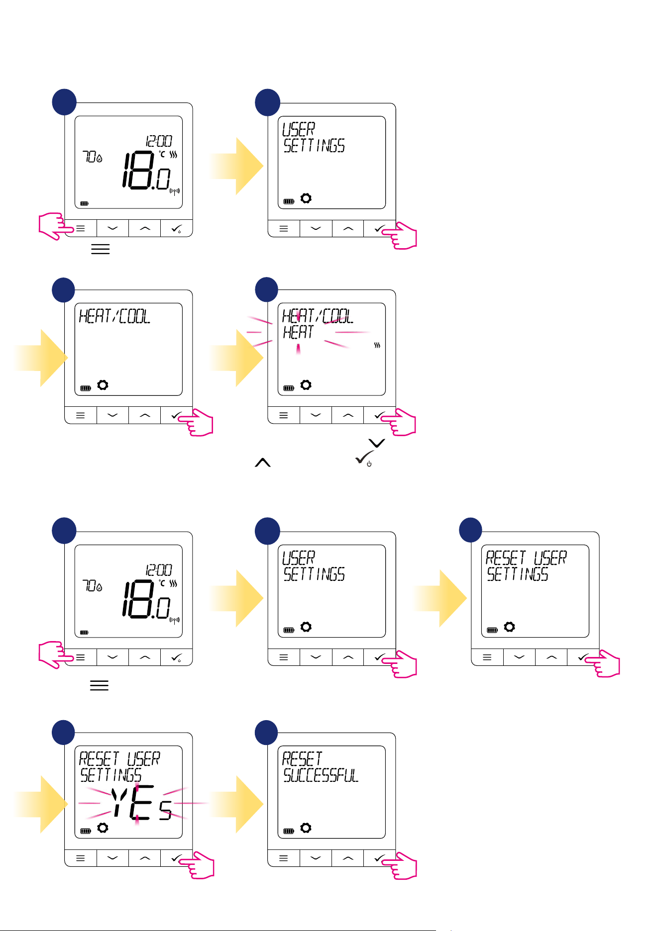
8.6.7 Heat/cool selection
SQ610RF thermostat can work in heating or cooling mode. To set thermostat operating mode please follow steps below:
NOTE: Available only if thermostat is paired with Smart Plug SPE600 or Smart Relay SR600 in ONLINE MODE.
1
2
Select heat or cool mode by or
buttons. Conrm by button.
3
4
8.6.8 Reset user settings
1
2
3
4
5
To reset user settings to it’s default please follow steps below:
Go to the user settings.
Press button to enter the
main menu.
Choose heat/cool option.
Go to the user settings.
Press button to enter the
main menu.
Choose reset user settings.
Conrm reset by choosing YES.
User settings has been
successfully reseted.
61
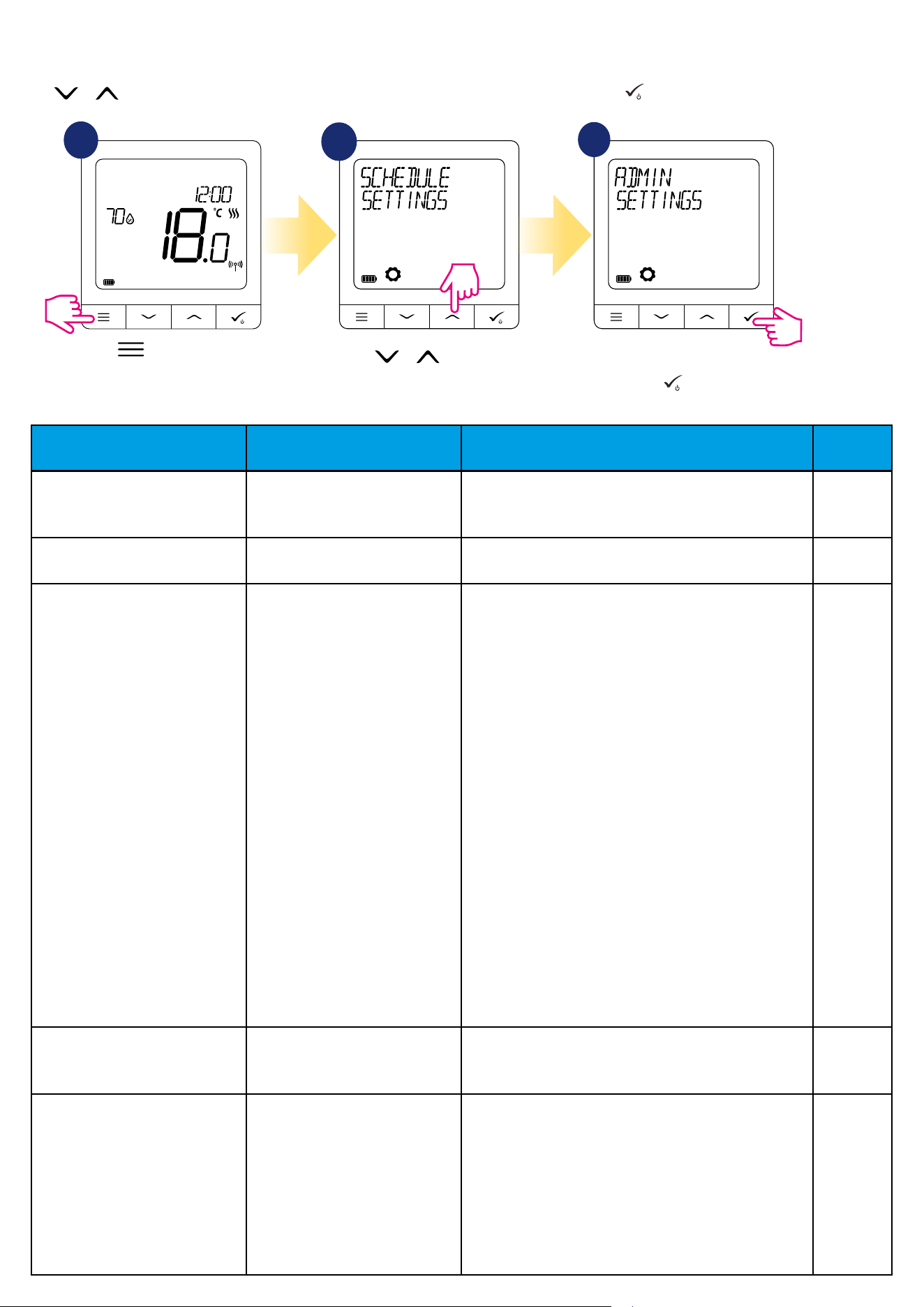
9. Admin settings (installer parameters)
To enter admin settings (installer parameters) please follow steps below. Please refer to parameters table description before any changes.
Use or buttons to move up or down between all parameters. Every change/selection conrm by button:
1
2
3
TEMPERATURE SCALE CELSIUS ⁰C
FAHRENHEIT ⁰F
This parameter species temperature unit of the thermostat. ⁰C
DISPLAY TEMP RESOLUTION 0.5 ⁰C / 0.1 ⁰C
1 ⁰F / 0.2 ⁰F
This parameter species the accuracy of the displayed
(measured) temperature.
0.5⁰C / 1⁰F
HEAT CONTROL ALGORITHM ITLC UFH
ITLC RAD
ITLC ELECT
SPAN +/- 0.25 ⁰C (0.5 ⁰F)
SPAN +/- 0.5 ⁰C (1 ⁰F)
THB ACTUATOR
This parameter denes the algorith of the room temperature
control.
ITLC algorithm ensures reduction of overdrive states and
economic operation of the system. It is an advanced algorithm
designed to precisely maintain room temperature.
ITLC UFH - algorithm designed for underoor heating (for
heating systems with high inertia),
ITLC RAD - algorithm designed for radiator heating,
ITLC ELECT - algorithm for electric heating (for heating systems
that heat up quickly and cool down quickly)
SPAN +/- 0.25⁰C (+/- 0.5⁰F)
SPAN +/- 0.5⁰C (+/- 1.0⁰F)
THB ACTUATOR - an algorithm designed for underoor
heating systems which are equipped with THB actuators with
automatic ow balancing function (dynamic ow control).
The THB actuator has two temperature sensors that are
installed on the supply and return of the corresponding loop of
the underoor heating. The self-regulating actuator measures
temperature on the sensors and adjusts its work to maintain
the correct temperature dierence between the supply and
return ows(ΔT).
ITLC UFH
COOL CONTROL ALGORITHM SPAN +/- 0.25 ⁰C (0.5 ⁰F)
SPAN +/- 0.5 ⁰C (1 ⁰F)
This parameter denes SPAN setting for cooling mode. SPAN +/-
0.25 ⁰C /
0.5 ⁰F
TRV ADVANCED CALIBRATION OFF
AUTO SELECT
ON
This parameter is only available when thermostat is paired with
the TRV head. This function runs an advanced self-learning
algorithm for systems not equipped with the RX10RF receiver.
System performs very accurate calibration of TRV head in order
to self-adapt to room conditions.
OFF
This option should be used in a system equipped with the
RX10RF (RX1) module to control the boiler. The advantage of
AUTO
SELECT
Parameter name Parameter Values Description Default
Values
Move or buttons to
look for Admin Settings.
Press button to enter the
main menu.
When you will nd Admin settings
then enter by button.

62
this algorithm is that the heating process begins with the TRV
heads opening and ensures the ow in the system before the
boiler starts. The system also turns o the boiler via the RX10RF
(RX1) module before all TRV heads are closed.
AUTO
Default setting (AUTO) means system decides itself which
control algorithm to choose:
• if thermostat works in the system together with RX10RF
(RX1) (which controls boiler), then TRV heads will be controlled
according to „OFF” algorithm described above,
• if there is no RX10RF (RX1) - then thermostat selects the
self-learning algorithm „ON” (Advanced Self Learning Control)
described below
ON
Advanced Self Learning Control - an advanced self-learning
algorithm.
This algorithm is intended for systems that are not equipped
with the RX10RF (RX1) module. Hydraulic system must have
by-pass - boiler still can operate when all TRV heads are closed.
The correct operation of the algorithm consists in double
calibration process of the TRV head:
• standard - during TRV head installation on the valve.
• precise - to self-adapt to room conditions and maintain a
stable temperature.
Advanced calibration can take several hours (or even more if 1
thermostat controls several TRV heads simultaneously). While
thermostat is performing calibration process, message „RADIA-
TOR TRV CALIBRATING” appears on the display.
WARNING! Calibration process performs automatically. There is
no need to force it manually.
S1/S2 INPUT DISABLE
FLOOR SENSOR
EXT SENSOR
OCCUP SENSOR
ONE TOUCH
CHANGEOVER
S1/S2 input can work in various congurations:
DISABLE - S1/S2 input is o.
FLOOR SENSOR - S1/S2 input is used for oor temperature
sensor connection (e.g. FS300 - NTC 10kOhm). Thermostat
maintains temperature in the room and additionaly (by oor
sensor) prevents oor against overheating or overcooling which
may cause discomfort or oor damage.
EXT SENSOR - S1/S2 input is used for external temperatu-
re sensor connection (e.g. FS300 - NTC 10kOhm). When an
external temperature sensor is connected, thermostat will
display temperature measured by this sensor and will ignore
the internal built-in sensor. An external temperature sensor can
be used when thermostat is controlling room to which we don’t
have access. Please note that if no external sensor is connected
and you have chosen to use the S1/S2 input as „EXT SENSOR”,
the temperature will not be displayed.
OCCUP SENSOR - an external volt-free contact is connected to
the S1/S2 input (e.g. hotel card, occupancy sensor).
When S1/S2 contacts are closed, thermostat is in normal
operation mode e.g. schedule mode or manual mode.
DISABLE
Parameter name Parameter Values Description Default
Values

63
Parameter name Parameter Values Description Default
Values
MAXIMUM SETPOINT MAX SETPOINT FOR HEATING
MAX SETPOINT FOR COOLING
This parameter allows to limit temperature setpoint range by
setting maximum setpoint for heating and cooling modes.
Default temperature setting range: 5,5⁰C - 40⁰C
35 ⁰C
VALVE PROTECTION ON
OFF
Valve protection function is intended to protect thermostatic
valves against getting stuck or jamming (e.g. in summer time
when heating system is disabled). If thermostat doesn’t send a
signal for heating for a period of 7 days, then heating is turned
on for a very short period of time just to move the actuators.
ON
MINIMUM TURN-OFF TIME MIN OFF TIME FOR COOLING This parameter species the minimum time between ON/OFF
switching in cooling mode. Thermostat have to wait this time
value before it switches on again.
Minimum Turn-O time range: 0 - 300
COOLING:
180
OPTIMISATION FEATURE OPTIMUM START ON / OFF
OPTIMUM STOP ON / OFF
Optimisation function is an energy-saving algorithm for eec-
tive control of the heating device ensuring better temperature
comfort at pre-dened times of the day.
When the OPTIMUM START function is active, thermostats
sends the heating signal to the heat source earlier so that the
setpoint temperature is reached at the time dened in the
schedule.
When the OPTIMUM STOP function is active, thermostat takes
into account the system inertia, switches o the heat source
earlier to reach setpoint temperature at the time dened in the
schedule.
OPTIMUM
START: OFF
OPTIMUM
STOP: OFF
COMFORT WARM FLOOR DISABLE
LEVEL 1
LEVEL 2
LEVEL 3
This function helps to keep the oor warm, even if the room is
warm enough and there is no need to turn on the heating. User
can select 3 levels of warm oor feature.
PLEASE NOTE: it is not an economy feature, as your heating
system may be ON even if there is no heating demand from the
room thermostat. It is COMFORT feature which keeps your oor
warm all the time. It is only for Heating Mode.
DISABLE
When S1/S2 contacts are opened, thermostat activates standby
mode
ONE TOUCH - this option is available only in ONLINE mode. In
this scenario S1/S2 input is used to work with volt-free contact.
By closing/opening S1/S2 contacts we can trigger any OneTouch
rule created in the Smart Home application. More information
in chapter 6.15
CHANGEOVER - an external volt-free contact is connected to
the S1/S2 input.
When S1/S2 contacts are closed, thermostat works in heating
mode.
When S1/S2 contacts are opened, thermostat works in cooling
mode.
This function is not available when thermostat is paired with
KL08RF wiring centre, TRV head or RX10RF receiver.
MINIMUM SETPOINT MIN SETPOINT FOR HEATING
MIN SETPOINT FOR COOLING
This parameter allows to limit temperature setpoint range by
setting minimum setpoint for heating and cooling modes.
Default temperature setting range: 5⁰C - 35⁰C
5 ⁰C
64
- LEVEL 1 - Heating will be ON for 11min (3min to open the actuator, then
actuator will remain open for 5min, then closing the actuator will take
another 3min). The option is for small rooms with short loops, which can be
heated up quickly.
- LEVEL 2 - Heating will be ON for 15min (3min to open the actuator, then
actuator will remain open for 9min, then closing the actuator will take
another 3min). The option is for medium rooms with loops of medium
length.
- LEVEL 3 - Heating will be ON for 19min (3min to open the actuator, then
actuator will remain open for 13min, then closing the actuator will take
another 3min). The option is for big rooms, with long loops.
PIN CODE DISABLE
ENABLE
There are two variants that can be set for the PIN CODE feature:
- PIN CODE will be used only to lock admin settings menu,
- PIN CODE will be used to completely lock thermostat.
PIN CODE can be set from the Smart Home application or from device side.
In case of any problems with thermostat unlocking, please contact the
SALUS-Controls Technical Department.
DISABLE
DEVICE INFORMATION PAIRED WITH
RF RANGE
BATTERY LEVEL
IDENTIFY MODE
SOFT
DEL OFFLINE DEVICE
This function helps user to nd out below informations about thermostat:
PAIRED WITH - here we can check which devices are controlled by
thermostat
RF RANGE - this screen displays the value of RSSI (Received Signal Strength
Indicator) between thermostat and coordinator (UGE600 or CO10RF) every
3 seconds. If the wireless connection is lost, „LOST LINK” information is
displayed.
BATTERY LEVEL - information about percentage battery level status
IDENTIFY DEVICES - press button to enable identication process from
device side - you can check which devices are paired with thermostat (e.g.
wiring centre, TRV head etc.). During identication time of 10 minutes are
counted down. Press again button to end identication process earlier.
SOFT - information about thermostat rmware version
DELETE OFFLINE DEVICE - this function is available only when thermostat
is paired with CO10RF coordinator (in OFFLINE mode). It allows user to
remove OFFLINE devices which are still present in the CO10RF memory. In
a properly working network all devices should communicate. If there is any
device installed in the network and it is turned o from the power supply or
out of range (so it is not communicating with the network) it can be deleted
from thermostat side.
EXAMPLE:
Choose the oine device type you wish to delete:
CONTROL BOX, THERMOSTAT, RADIATORS, RX10RF RX1, RX10RF RX2.
After conrming the selection (e.g THERMOSTAT), use the „up” and „down”
keys and the following informations will be displayed:
- number of all devices in the network (e.g. THERMOSTAT 08 ALL)
- number of devices which are communicating with coordinator, (e.g.
REGULATOR 06 ONLINE)
- number of devices which are disconnected from power supply or out of
range (e.g. REGULATOR 02 OFFLINE).
At this point, pressing button conrms oine devices removal.
Parameter name Parameter Values Description Default
Values
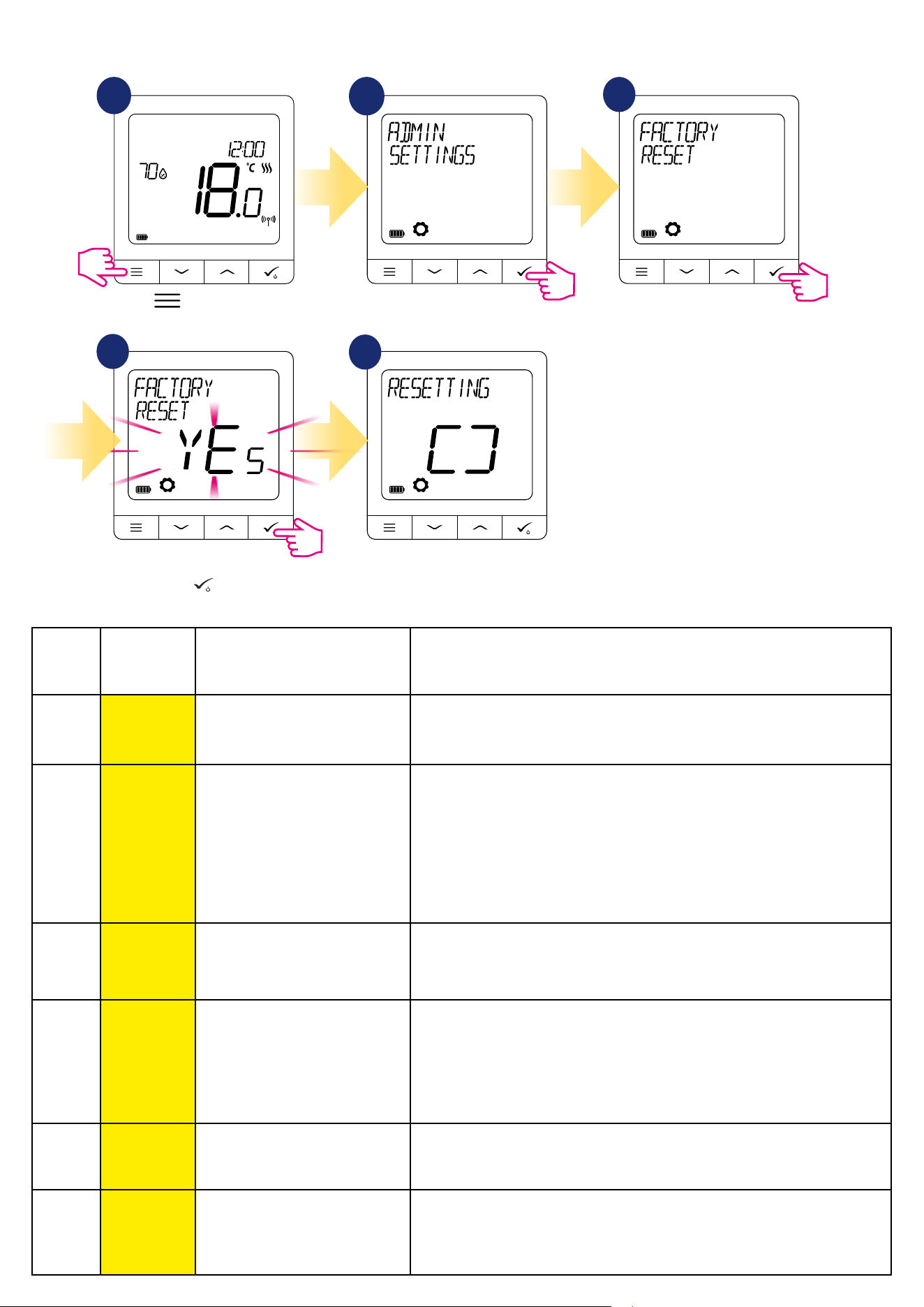
65
10. Factory Reset
To RESET SQ610RF thermostat to it’s factory default settings please follow steps below:
1
2
3
4
5
11. Error codes (error codes description with possible solutions)
ERROR
CODE
DISPLAY
DESCRIPTION
ERROR DESCRIPTION TROUBLESHOOTING
1.
TRV
HARDWARE
PROBLEM
TRV paired with thermostat - TRV
hardware error.
• Reinstall the TRV head or replace it. If necessary, contact with the
SALUS Technical Department.
2.
FLOOR
SENSOR
OVERHEATED/
OVERCOOLED
Floor is overheated (heating mode).
/ Floor is overcooled (in cooling
mode).
• Set the heating medium temperature or change oor sensor MAX/
MIN temperature setpoint in the „S1/S2 input” admin setting parame-
ter.
• Set the cooling medium temperature or change oor sensor MAX/
MIN temperature setpoint in the „S1/S2 input” admin setting
parameter.
3.
FLOOR
SENSOR
DEFECT
Floor sensor is broken.
• If oor sensor is connected to „S1/S2 input”, check the wiring.
• If oor sensor is not connected, check the „S1/S2 input” parameters
settings.
4.
FLOOR
SENSOR
DEFECT
Floor sensor is shorted.
• If oor sensor is connected to „S1/S2 input”, check the wiring.
• If oor sensor is not connected, check the „S1/S2 input” parameters
settings.
• Check oor sensor wire insulation for any damages. Sensor resistance for
25°C=10kΩ.
5.
CONNECTIVITY
LOST COORD.
Thermostat lost contact with the
CO10RF network coordinator or the
UGE600 internet gateway.
• Check the coordinator/gateway power supply connection.
• Force identication process from the coordinator/gateway or thermostat.
6.
CONNECTIVITY
LOST WC
Thermostat lost connection with the
wiring centre.
Is the wiring centre turned ON and Status Network LED diode solid?
• If yes, send the heating signal from thermostat to the wiring centre
(change setpoint temperature).
Wait few moments to nish factory
reset procedure.
Go to the Admin Settings.
Press button to enter the
main menu.
Choose „Factory Reset” option.
Select YES and conrm choice by
pressing
button
.

66
• If LED diode of the Network Status is ashing, pair the wiring centre with
the system in accordance to the manual instruction and pair thermostat
with wiring centre.
7.
CONNECTIVITY
LOST TRV
Thermostat lost contact with the TRV
head.
• Check TRV head batteries.
• Send the heating signal from thermostat and check if the TRV
head is working.
• If the LED diode on the TRV head is ashing, repeat the pairing
procedure with thermostat according to the manual instructions.
8.
CONNECTIVITY
LOST RX 1
Thermostat has lost connection with
the RX10RF receiver (RX1 mode).
• Is the RX10RF receiver plugged to the power supply and the top
LED diode is red? The Auto/Manual switch has to be set to AUTO
position.
• Force identication process from the coordinator/gateway side
and check if the devices are within the network.
• Send the heating signal from thermostat
• If the top LED diode is ashing, perform the pairing procedure
according to the RX10RF manual instruction.
9.
CONNECTIVITY
LOST RX 2
Thermostat has lost connection with
the RX10RF receiver (RX2 mode).
• Is the RX10RF receiver plugged to the power supply and the top
LED diode is red? The Auto/Manual switch has to be set to AUTO
position.
• Force identication process from the coordinator/gateway side
and check if the devices are within the network.
• Send the heating signal from thermostat
• If the top LED diode is ashing, perform the pairing procedure
according to the RX10RF manual instruction.
11-18.
CONNECTIVITY
LOST ZONE 1-8
Wiring centre has lost connection
with thermostat of the given zone:
e.g. 11 = with zone 1; 12 = with the
zone 2 etc. Error is displayed on all
thermostats.
• Check the thermostat power supply.
• Send the heating signal from thermostat.
• If necessary, reinstall the thermostat.
19.
WC / CB LOST
CONNECTIVITY
Wiring centre has lost connection
with the CO10RF coordinator/UGE600
internet gateway.
Error is displayed on all thermostats.
• Is the wiring centre turned ON and Status Network LED diode
solid?
• Force identication process from the coordinator/gateway side
and check if wiring centre is within the network.
• If LED diode of the Network Status is ashing, pair the wiring
centre with the system in accordance to the manual instruction and
pair all thermostats with wiring centre.
20.
WC / CB LOST
LINK-RX10RF
Wiring centre has lost connection
with the RX10RF receiver operating in
RX1 mode.
Error is displayed on all thermostats.
• Is the wiring centre turned on? Status Network LED diode should
be solid.
• Force identication process from the coordinator/gateway side
and check if devices are within the network.
• If the LED diode of the AUTO/MANUAL receiver switch is ashing,
follow the RX10RF manual instruction for pairing.
ERROR
CODE
DISPLAY
DESCRIPTION
ERROR DESCRIPTION TROUBLESHOOTING

67
24.
THERMOSTAT
REJECTED WC
Thermostat was rejected by the
wiring centre.
• Perform the thermostat’s pairing procedure again.
25.
CONNECTIVITY
LOST
Thermostat has lost connection with
the nearest 230V powered device.
• Check the power supply of the nearest 230V device. If there is problem
with RF signal range, install the ZigBee Network Repeater and pair
thermostat with the receiver again (wiring centre, TRV head etc.)
26-29.
CONNECTIVITY
LOST ZONE
9-12
Wiring centre has lost connection
with thermostat of the given zone:
e.g. 26 = with zone 9; 27 = with
zone 10; 28 = with zone 11, 29 =
with zone 12. Error is displayed on all
thermostats.
• Check the thermostat’s power supply.
• Send the heating signal from thermostat.
• If necessary, reinstall the thermostat.
30.
TRV GEAR
DEFECT
TRV head has a problem with the
internal gear mechanism.
• Reinstall the TRV head or replace it. If necessary, contact with the
SALUS Technical Department.
31.
TRV FAILED
ADAPTATION
Adaptation error of the TRV head
assembled on the radiator valve
insert.
• Check assembly of the TRV head on radiator valve insert and reinstall
the TRV head.
• Check the compatibility of the TRV head and radiator valve insert;
replace the valve insert if necessary.
32.
THERMOSTAT
LOW BATTERY
Thermostat’s battery level is low
(error is displayed only in the Smart
Home application).
• Replace thermostat batteries.
33.
CONNECTIVITY
LOST RX10RF
The RX10RF receiver has lost
connection with thermostat (error
is displayed only in the Smart Home
application).
• Check the thermostat’s power supply.
• Force identication process from the coordinator/gateway side and
check if devices are within the network.
• Send the heating signal from thermostat side and check if RX10RF
receiver is turning ON.
• If the top LED diode is ashing, perform the pairing procedure
according to the RX10RF manual instruction.
• Pair thermostat with the RX10RF receiver again according to the ther-
mostat’s manual instruction.
ERROR
CODE
DISPLAY
DESCRIPTION
ERROR DESCRIPTION TROUBLESHOOTING
22.
TRV
LOW BATTERY
Low battery level in the TRV head.
• Replace TRV head batteries.
23.
UNPAIRED TRV
WITHIN RANGE
TRV head’s pairing error or head is
incompatible with the system.
• Remove TRV head from the system and repeat pairing procedure with
thermostat.
21.
CONNECTIVITY
LOST COORD.
TRV head has lost connection with
CO10RF coordinator/UGE600 internet
gateway.
• Check TRV head batteries (replace if necessary).
• Check if the coordinator/ internet gateway is connected to the power
supply.
• Force identication process from the coordinator/gateway side and
check if devices are within the network.
• Send the heating signal from thermostat.
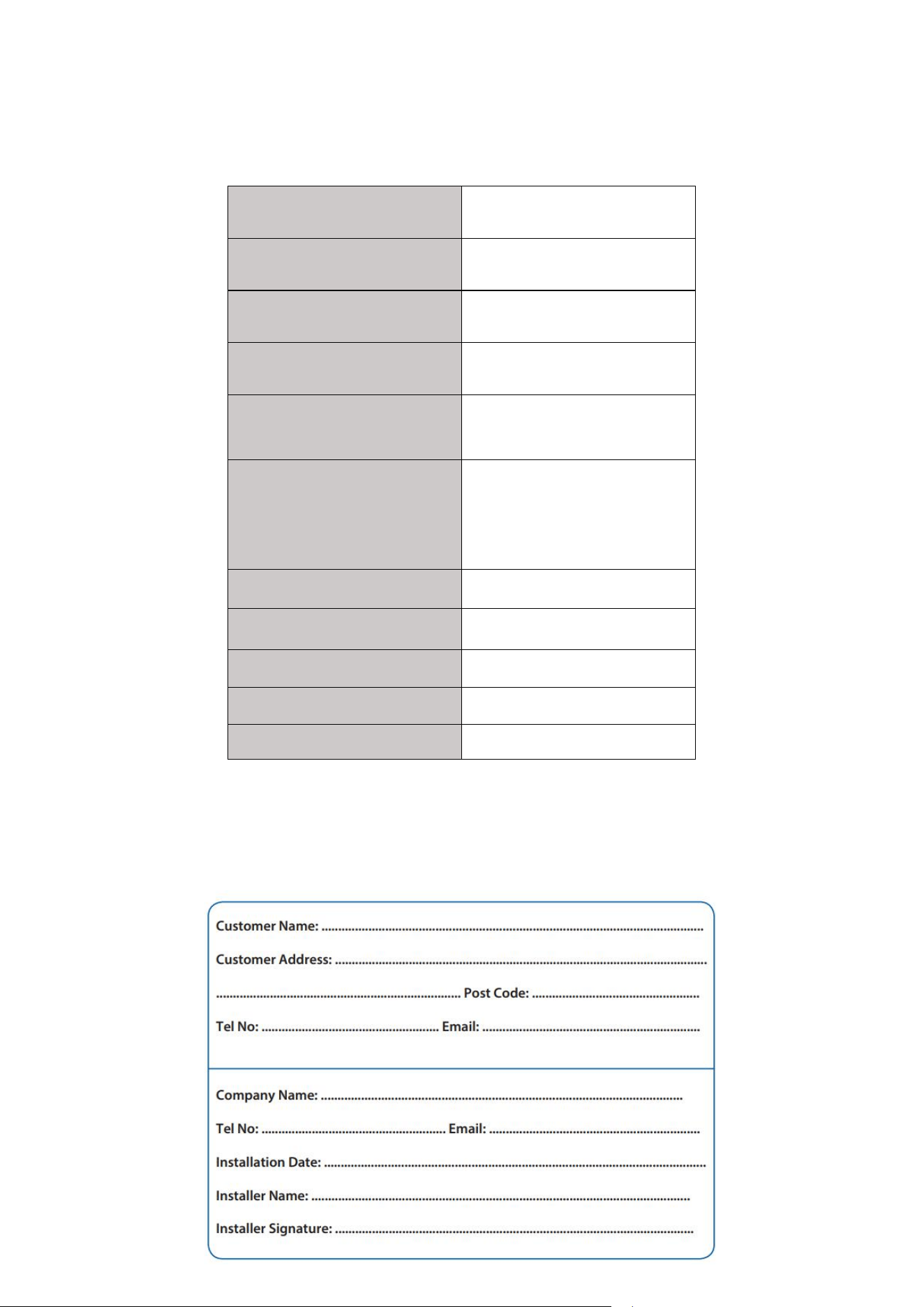
68
The SQ610RF Quantum Thermostat requires no special maintenance. Periodically, the outer casing can be wiped clean using a dry cloth (please DO
NOT use solvents, polishes, detergents or abrasive cleaners, as these can damage the thermostat). There are no user serviceable parts within the unit; any
servicing or repairs could only be carried out by Salus Controls or their appointed agents.
12. Cleaning and Maintenance
13. Technical Informations
14. Warranty
SALUS Controls warrants that this product will be free from any defect in materials or workmanship, and shall perform in accordance with its specication,
for a period of ve years from the date of installation. SALUS Controls sole liability for breach of this warranty will be (at its option) to repair or replace the
defective product.
Power Supply Built-in Li-ion 3,7V Battery
Charging voltage (no charger included) Micro-USB 5V DC, min 0,5A
Temperature range 5-40°C
Display temperature accuracy 0.5°C or 0.1°C
Control algorithm
ITLC
SPAN (±0.25°C / ±0.5°C)
THB
S1-S2 input (multifunctional input)
Floor temperature
Air temperature
Occupancy sensor
One Touch
Changeover (heating/cooling)
Communication protocol ZigBee 2,4GHz
Mounting Surface mounting
Working temperature 0-45°C
IP protection class IP30
Dimensions (Width x Height x Deep) 86 x 86 x 11 mm
IMPORTER:
SALUS Controls Plc
Units 8-10 Northfield Business Park
Forge Way, Parkgate
Rotherham
S60 1SD
United Kingdom
DISTRIBUTOR OF SALUS CONTROLS:
QL CONTROLS Sp. z o.o., Sp. k.
Rolna 4,
43-262 Kobielice,
Poland
www.salus-controls.com
SALUS Controls is a member of the Computime Group.
Maintaining a policy of continuous product development SALUS Controls plc reserve the right to change
specification, design and materials of products listed in this brochure without prior notice.
Issued: December 2019