
1
VENT-FREE GAS FIREPLACE
INSTALLER: Leave this manual with the appliance.
CONSUMER: Retain this manual for future reference.
WARNING: IF THE INFORMATION IN THIS MANUAL IS NOT FOLLOWED
EXACTLY, A FIRE OR EXPLOSION MAY RESULT CAUSING PROPERTY
DAMAGE, PERSONAL INJURY OR LOSS OF LIFE.
CAUTION - FOR YOUR SAFETY
Questions, problems, missing parts? Before returning to your retailer, call our customer
service department at 1-877-447-4768, 8:30 a.m. – 4:30 p.m., CST, Monday – Friday or
email us at [email protected].
WARNING: This appliance
is equipped for (Natural or Pro-
pane) gas. Field conversion is
not permitted.
- Do not store or use gasoline or other ammable vapors and Iiquids in vicinity of this or
any other appliance.
WHAT TO DO IF YOU SMELL GAS
• Do not try to light any appliance.
• Do not touch any electrical switch; do not use any phone in your building.
• Immediately call your gas supplier from a neighbor’s phone. Follow the gas supplier’s
instructions.
• If you cannot reach your gas supplier, call the re department.
- Installation and service must be performed by a qualied installer, service agency or the
gas supplier.
This is an unvented gas-red heater. It uses air (oxygen) from the room in which it is
installed. Provisions for adequate combustion and ventilation air most be provided.
Refer to Air For Combustion and Ventilation section on page 9-11 of this manual.
This appliance may be installed in an aftermarket, permanently located manufactured (mobile)
home, where not prohibited by local codes.
This appliance is only for use with the type of gas indicated on the rating plate.
This appliance is not convertible for use with other gases.
0418GF006S
ANSI Z21.11.2-2013
80-10-352 - 2016-05-03
Propane
VFF-PH(20LPB)(20LP)(20LP-C2)(20LP-2T2)
VFF-PH(26LP)(26LP-T2)(26LP-2H2)
VFF-PH(32LPB)(32LP)(32LP-H2)(32LP-2C2)
Natural Gas
VFF-PH(20NGB)(20NG)(20NG-C1)(20NG-2T1)
VFF-PH(26NG)(26NG-T1)(26NG-2H1)
VFF-PH(32NGB)(32NG)(32NG-H1)(32NG-2C1)

2
WARNING: Read the Installation & Operating Instructions before using this appliance.
IMPORTANT: Read all instructions and warnings carefully before starting installation.
Failure to follow these instructions may result in possible injury to persons or a re
hazard and will void the warranty.
TABLE OF CONTENTS
Specications ................................................................................................................................... 2
Important Safety Information ............................................................................................................3
Product Identication ........................................................................................................................ 5
Product Features .............................................................................................................................. 6
Unpacking......................................................................................................................................... 6
Hood Assembly................................................................................................................................. 7
Preparing for Installation................................................................................................................... 8
Installation ...................................................................................................................................... 11
Operation ........................................................................................................................................ 23
Remote Control Operation...............................................................................................................25
Care and Maintenance ................................................................................................................... 32
Troubleshooting .............................................................................................................................. 35
Replacement Parts ......................................................................................................................... 37
Accessories .................................................................................................................................... 38
Warranty ......................................................................................................................................... 40
SERVICE HINTS
When Gas Pressure Is Too Low
• pilot will not stay lit
• burners will have delayed ignition
• replace will not produce specied heat
• for propane/LP units, propane/LP gas supply may be low
You may feel your gas pressure is too low. If so, contact your local natural or propane/LP gas supplier.
Model VFF-PH20LP Series VFF-PH26LP Series VFF-PH32LP Series
Input Rating 20,000 BTU 27,500 BTU 32,000 BTU
MIN Input Rating 18,000 BTU 25,000 BTU N/A
Gas Type LP LP LP
Manifold Pressure 10’’ WC 10’’ WC 10’’ WC
Max. Inlet Pressure 14’’ WC 14’’ WC 14’’ WC
Min. Inlet Pressure 11’’ WC 11’’ WC 11’’ WC
Model VFF-PH20NG Series VFF-PH26NG Series VFF-PH32NG Series
Input Rating 20,000 BTU 27,500 BTU 32,000 BTU
MIN Input Rating 15,000 BTU 20,500 BTU N/A
Gas Type NG NG NG
Manifold Pressure 5’’ WC 5’’ WC 5’’ WC
Max. Inlet Pressure 11’’ WC 11’’ WC 11’’ WC
Min. Inlet Pressure 7’’ WC 7’’ WC 7’’ WC
3
IMPORTANT: Read this owner’s manual carefully and completely before trying to assemble, operate,
or service this heater. Improper use of this heater can cause serious injury or death from burns, re,
explosion, electrical shock, and carbon monoxide poisoning.
IMPORTANT SAFETY INFORMATION
Only a qualied installer, service agent, or local gas supplier may install and service this product.
WARNING: Do not store or use gasoline or other ammable vapors or liquids in the vicinity
of this or any other appliance.
WARNING: This appliance can be used with propane or natural gas.
CARBON MONOXIDE POISONING: Early signs of carbon monoxide poisoning resemble the u
with headaches, dizziness, or nausea. If you have these signs, the heater may not be working properly.
Get fresh air immediately! Have heater serviced. Some people are more affected by carbon monoxide
than others. These include pregnant women, people with heart or lung disease, people who are
anemic, those under the inuence of alcohol, and those living in high altitudes.
NATURAL AND PROPANE/LP GAS: Natural and Propane/LP gases are odorless. An odor-making
agent is added to the gas. The odor helps you detect a gas leak. However, the odor added to the
gas can fade. Gas may be present even though no odor exists. Make certain you read and under-
stand all warnings. Keep this manual for reference. It is your guide to operating this heater safely.
WARNING: Any change to this replace/heater or its controls can be dangerous.
WARNING: Do not use any accessories not approved for use with this heater.
WARNING: Carefully supervise young children when they are in the room with the heater.
WARNING: Heater becomes very hot when operating. Keep children and adults away from hot
surfaces to avoid burns or clothing ignition. Heater will remain hot for a time after shutoff. Allow
surfaces to cool before touching.
WARNING: Keep the appliance area clear and free from combustible materials, gasoline, and
other ammable vapors and liquids.
WARNING: Due to high temperatures, locate this appliance out of trafc and away from
furniture and draperies.
WARNING: Do not place clothing or other ammable material on or near the appliance. Never
place any objects in the heater.
CALIFORNIA PROPOSITION 65
Fuels used in gas or oil red appliances and the products of combustion of such fuels contain
chemicals known to the state of California to cause cancer, birth defects or other reproductive
harm. This product contains chemicals, including lead and lead compounds, known to the state of
California to cause cancer, birth defects or other reproductive harm. Wash hands after handling.

4
SAFETY INFORMATION
1. This appliance is only for use with the type of gas indicated on the rating plate. This appliance is
not convertible for use with other gases.
2.
Do not place propane/LP supply tank(s) inside any structure. Locate propane/LP supply tank(s) outdoors.
3. If you smell gas
• shut off gas supply
• do not try to light any appliance
• do not touch any electrical switch; do not use any phone in your building
• immediately call your gas supplier from a neighbor’s phone. Follow the gas supplier’s instructions
• if you cannot reach your gas supplier, call the re department
4. This replace shall not be installed in a bedroom or bathroom.
5. Do not use this replace as a wood-burning replace. Use only the logs provided with the replace.
6. Do not add extra logs or ornaments such as pine cones, vermiculite or rock wool. Using these
added items can cause sooting. Do not add lava rock around base. Rock and debris could fall into
the control area of replace.
7. This replace is designed to be smokeless. If logs ever appear to smoke, turn off replace and
call a qualied service person. Note: During initial operation, slight smoking could occur due to log
curing and replace burning manufacturing residues.
8. To prevent the creation of soot, follow the instructions in Cleaning and Maintenance, page 32.
9. Before using furniture polish, wax, carpet cleaner or similar products, turn replace off. If heated,
the vapors from these products may create a white powder residue within burner box or on adjacent
walls or furniture.
10. This replace needs fresh air ventilation to run properly. This replace has an Oxygen Depletion
Sensing (ODS) safety shutoff system. The ODS shuts down the replace if not enough fresh air is
available. See Air for Combustion and Ventilation, page 9-11. If replace keeps shutting off, see
Troubleshooting, page 34.
11. Do not run replace
• where ammable liquids or vapors are used or stored.
• under dusty conditions.
12. Do not use this replace to cook food or burn paper or other objects.
13. Never place any objects in the replace or on logs.
14. Do not use replace if any part has been under water. Immediately call a qualied service technician
to inspect the room replace and to replace any part of the control system and any gas control which
has been under water.
15. Turn off and unplug replace and let cool before servicing. Only a qualied service person
should service and repair replace.
16. Operating replace above elevations of 4,500 feet could cause pilot outage.
17.
Do not operate replace if log is broken. Do not operate replace if log is chipped (dime-sized or larger).
18. To prevent performance problems, do not use propane/LP fuel tank of less than 100 lb. capacity.
19. Provide adequate clearances around air openings.
QUALIFIED INSTALLING AGENCY
Only a qualied agency should install and
replace gas piping, gas utilization equip-
ment or accessories, and repair and equip-
ment servicing. The term "qualied agency"
means any individual, rm, corporation, or
company that either in person or through a
representative is engaged in and is respon-
sible for:
a) Installing, testing, or replacing gas piping or
b)Connecting, installing, testing, repairing, or
servicing equipment; that is experienced in
such work; that is familiar with all precautions
required; and that has complied with all the re-
quirements of the authority having jurisdiction.
5
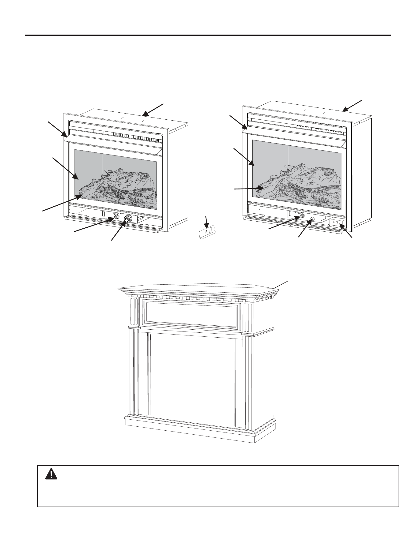
Screen
Log
Ignitor Button
Hood
Fireplace
Cabinet
Control Knob
PRODUCT IDENTIFICATION
Screen
Log
Ignitor Button
Hood
Fireplace
Cabinet
Control Knob EI Receiver
Remote
Transmitter
Mantel
Cabinet
WARNING: This replace is designed for use with the mantel cabinet provided. Installing
the replace cabinet without the provided mantel or substituting another mantel will void the
warranty and could resuly in property damage and personal injury.
Fig. 1 - Vent-Free Dual Fuel Fireplace
VFF-PH(20NGB)(20NG)(20NG-C1)(20NG-2T1)
VFF-PH(20LPB)(20LP)(20LP-C2)(20LP-2T2)
VFF-PH(26NG)(26NG-T1)(26NG-2H1)
VFF-PH(26LP)(26LP-T2)(26LP-2H2)
VFF-PH(32NGB)(32NG)(32NG-H1)(32NG-2C1)
VFF-PH(32LPB)(32LP)(32LP-H2)(32LP-2C2)
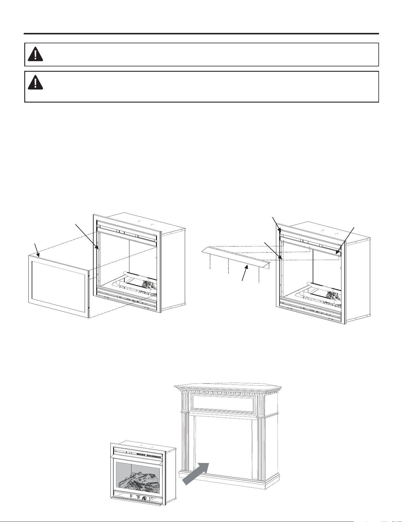
NOTE: The replace is installed into the mantel through the front opening of the mantel cabinet.
6
UNPACKING
1. Remove replace cabinet and hood from carton. Log is wrapped and inside replace.
Do not remove at this time.
2. Remove all protective packaging applied to replace for shipment.
3. Make sure your replace includes one hardware packet.
4. Check replace for any shipping damage. If replace is damaged, call GHP Group, Inc., at 1-877-
447-4768. Please do not return it to the store.
SAFETY PILOT
This heater has a pilot with an Oxygen Depletion Sensing (ODS) safety shutoff system.
The ODS/pilot shuts off the heater if there is not enough fresh air and cuts off main burner gas in the
event of ame out.
ELECTRIC PUSH BUTTON IGNITION SYSTEM
This heater is equipped with an electronic piezo control system. This system requires
one AAA battery (provided).
THERMOSTAT HEAT CONTROL
The control automatically cycles the burner on and off to maintain a desired room
temperature. See page 24.
BLOWER KIT (OPTIONAL)
The blower kit helps to distribute the warmed air into the space more rapidly.
State of Massachusetts: The installation must be made by a licensed plumber or gas tter in
the Commonwealth of Massachusetts. Sellers of unvented propane or natural gas-red
supplemental room heaters shall provide to each purchaser a copy of 527 CMR 30 upon sale
of the unit.
In the State of Massachusetts, unvented propane or natural gas-red space heaters shall
be prohibited in bedrooms and bathrooms.
In the State of Massachusetts the gas cock must be a T-handle type. The State of
Massachusetts requires that a exible appliance connector cannot exceed three feet
in length.
LOCAL CODES
Install and use heater with care. Follow all codes. In the absence of local codes, use the latest edi-
tion of The National Fuel Gas Code, ANSI Z223.1, also known as NFPA 54*.
*Available from:
American National Standard Institute, Inc. National Fire Protection Association, Inc.
1430 Broadway 1 Batterymarch Park
New York, NY 10018 Quincy, MA 02269-9101
This heater is designed for vent-free operation. State and local codes in some areas prohibit the use
of vent-free heaters.
PRODUCT FEATURES
7
HOOD ASSEMBLY (IF REQUIRED)
WARNING: Always have screen in place before operating replace. This prevents
excessive temperatures on replace surfaces.
WARNING: Failure to position the parts in accordance with these diagrams or failure to
use only parts specically approved with this replace may result in property damage
or personal injury.
Tools Required:
• Phillips screwdriver • scissors
1. If equipped, lift replace screen up and pull out to remove (See. Fig 2). Set screen aside until
installation has been completed.
2. Cut two plastic straps to remove log from rebox cavity. Set log aside.
3. An optional blower is available. See Accessories, page 38. Install optional blower now. Follow
installation instructions provided with blower.
4. Locate four black Phillips sheet metal screws in hardware packet.
5. Slide hood between louver and rebox top and align screw holes.
6. Insert screws as shown in Figure 3. Tighten screws rmly.
Fig. 2 - Removing and Installing Screen
Fig. 3 - Assembling Hood
(If Required)
Shoulder Screw
Screen
Firebox Top
Louver
Sheet Metal
Screws
Hood
Carefully lift the insert through the center opening in the front of the replace. Slide the insert back
through the opening until the metal trim makes contact with the front of the mantel.

8
PREPARING FOR INSTALLATION
AIR FOR COMBUSTION AND VENTILATION
WARNING: This heater shall not be installed in a room or space unless the required volume
of indoor combustion air is provided by the method described in the Nation Fuel Gas Code, ANSI
Z223.1/NFPA 54, the International Fuel Gas Code, or applicable local codes.
PRODUCING ADEQUATE VENTILATION
All spaces in homes fall into one of the three following ventilation classications:
1. Unusually Tight Construction
2. Unconned Space
3. Conned Space
The information on pages 9 through 11 will help you classify your space and provide adequate ventilation.
Conned and Unconned Space
A conned space as a space whose volume is less than 50 cu. ft. per 1,000 BTU/hr (4.8 m^3 per kw)
of the aggregate input rating of all appliances installed in that space and an unconning space as a
space whose volume is not less than 50 cu. ft. per 1,000 BTU/hr (4.8 m^3 per kw) of the aggregate
input rating of all appliances installed in that space. Rooms connecting directly with the space in
which the appliances are installed*, through openings not furnished with doors, are considered a
part of the unconned space.
This heater shall not be installed in a conned space or unusually tight construction unless provisions
are provided for adequate combustion and ventilation air.
* Adjoining rooms are connecting only if there are doorless passageways or ventilation
grills between them.
Unusually Tight Construction
The air that leaks around doors and windows may provide enough fresh air for combustion and venti-
lation. However, in buildings of unusually tight construction, you must provide additional
fresh air.
Unusually tight construction is dened as construction where:
a) walls and ceilings exposed to the outside atmosphere have a continuous water vapor retarder
with a rating of one perm (6x10-11kg per pa-sec-m2) or less with openings gasketed or sealed
and
b) weather stripping has been added on windows that can be opened and on doors and
c) caulking or sealants are applied to areas such as joints around window and door frames,
between sole plates and oors, between wall-ceiling joints, between wall panels, at
penetrations for plumbing, electrical, and gas lines, and at other openings.
If your home meets all of the three criteria above, you must provide additional fresh air.
See “Ventilation Air From Outdoors” (page 10). If your home does not meet all of the
three criteria above, proceed to “Determining Fresh-Air Flow For Heater Location”.

9
PREPARING FOR INSTALLATION
DETERMINING FRESH-AIR FLOW FOR HEATER LOCATION
Determining if You Have a Conned or Unconned Space
Use this worksheet to determine if you have a conned or unconned space.
Space: Includes the room in which you will install heater plus any adjoining rooms with
doorless passageways or ventilation grills between the rooms.
1. Determine the volume of the space Length × Width × Height = cu. ft. (volume of space)
Example: Space size 20 ft. (length) × 16 ft.(width) × 8 ft. (ceiling height) = 2560 cu. ft. (volume
of space)
If additional ventilation to adjoining room is supplied with grills or openings, add the volume of these
rooms to the total volume of the space.
2. Divide the space volume by 50 cu. ft. to determine the maximum BTU/hr the space can support.
_______ (volume of space) ÷ 50 cu. ft.= (Maximum BTU/hr the space can support)
Example: 2560 cu. ft. (volume of space) ÷ 50 cu. ft. = 51.2 or 51,200 (maximum BTU/hr the space
can support)
3. Add the BTU/hr of all fuel burning appliances in the space.
Vent-free heater _________ BTU/hr
Gas water heater* ________BTU/hr
Gas furnace _____________BTU/hr
Vented gas heater ________BTU/hr Example:
Gas heater logs __________BTU/hr Gas water heater 30,000 BTU/hr
Other gas appliances*+ ____BTU/hr Vent-free heater + 26,000 BTU/hr
Total = ____BTU/hr Total = 56,000 BTU/hr
*Do not include direct-vent gas appliances. Direct-vent draws combustion air from the
outdoors and vents to the outdoors.
4. Compare the maximum BTU/hr the space can support with the actual amount of BTU/hr used.
_______ BTU/hr (maximum the space can support)
_______ BTU/hr (actual amount of BTU/hr used).
Example : 51,200 BTU/hr (maximum the space can support) 56,000 BTU/hr (actual amount of
BTU/hr used)
The space in the above example is a conned space because the actual BTU/hr used is more than
the maximum BTU/hr the space can support.
You must provide additional fresh air. Your options are as follows:
a) Rework worksheet, adding the space of an adjoining room. If the extra space provides an
unconned space, remove door to adjoining room or add ventilation grills between rooms. See
“Ventilation Air From Inside Building,” page 11.
b) Vent room directly to the outdoors. See “Ventilation Air From Outdoors”, page 11.
c) Install a lower BTU/hr heater if lower BTU/hr size makes room unconned. If the actual BTU/hr
used is less than the maximum BTU/hr the space can support, the space is an unconned space.
You will need no additional fresh air ventilation.
10
PREPARING FOR INSTALLATION
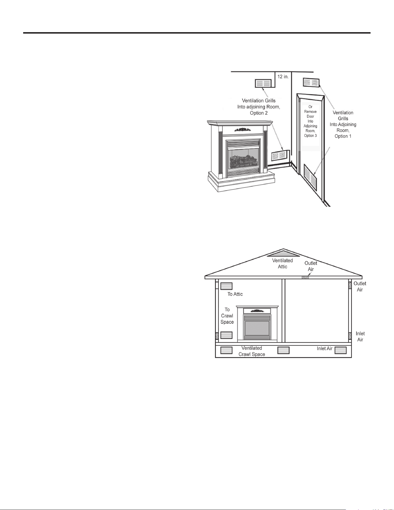
Ventilation Air From Inside Building
This fresh air would come from adjoining
unconned space. When ventilating to an
adjoining unconned space, you must
provide two permanent openings: one
within 12 in. of the wall connecting
the two spaces (see options 1 and 2,
Fig. 4). You can also remove door into
adjoining room (see option 3, Fig. 4).
Follow the National Fuel Gas Code
NFPA 54/ANS Z223.1. Air for Combustion
and Ventilation for required size of
ventilation grills or ducts.
Ventilation Air From Outdoors
Provide extra fresh air by using ventilation
grills or duct. You must provide two
permanent openings: one within 12 in. of
the ceiling and one within 12 in. of the oor.
Connect these items directly to the outdoors
or spaces open to the outdoors. These
spaces include attics and crawl spaces.
Follow the National Fuel Gas Code NFPA
54/ANS Z223.1. Air for Combustion and
Ventilation for required size of ventilation
grills or ducts.
IMPORTANT: Do not provide openings for
inlet or outlet air into attic if attic has a
thermostat-controlled power vent. Heated
air entering the attic will activate the power
vent. Rework worksheet, adding the space
of the adjoining unconned space. The
combined spaces must have enough fresh
air to supply all appliances in both spaces.
Fig. 4 - Ventilation Air from
Inside Building
Fig. 5 - Ventilation Air from Outdoors

11
INSTALLATION
NOTICE: This heater is intended for use as supplemental heat. Use this heater along with your
primary heating system. Do not install this heater as your primary heat source. If you have a
central heating system, you may run system’s circulating blower while using heater. This will
help circulate the heat throughout the house.
WARNING: A qualied technician must install heater. Follow all local codes.
WARNING: Never install the heater:
• in a bedroom or bathroom
• in a recreational vehicle
• where curtains, furniture, clothing, or other ammable objects are less than 42
in. from the front, top or sides of the heater.
• in high trafc areas
• in windy or drafty areas
WARNING: Maintain the minimum clearances. If possible, provide greater clearances from the
oor, ceiling, and adjoining wall than required.
CAUTION: This heater creates warm air currents. These currents move heat to wall surfaces next
to heater. Installing heater next to vinyl or cloth wall coverings or operating heater where impurities
(such as tobacco smoke, aromatic candles, cleaning uids, oil or kerosene lamps, etc.) in the air
exist, may cause walls to discolor.
IMPORTANT: Vent-free heaters add moisture to the air. Although this is benecial, installing heater in
rooms without enough ventilation air may cause mildew to form from too much moisture. See Air for
Combustion and Ventilation, pages 9 through 11.
CHECK GAS TYPE
Be sure your gas supply is right for your heater.
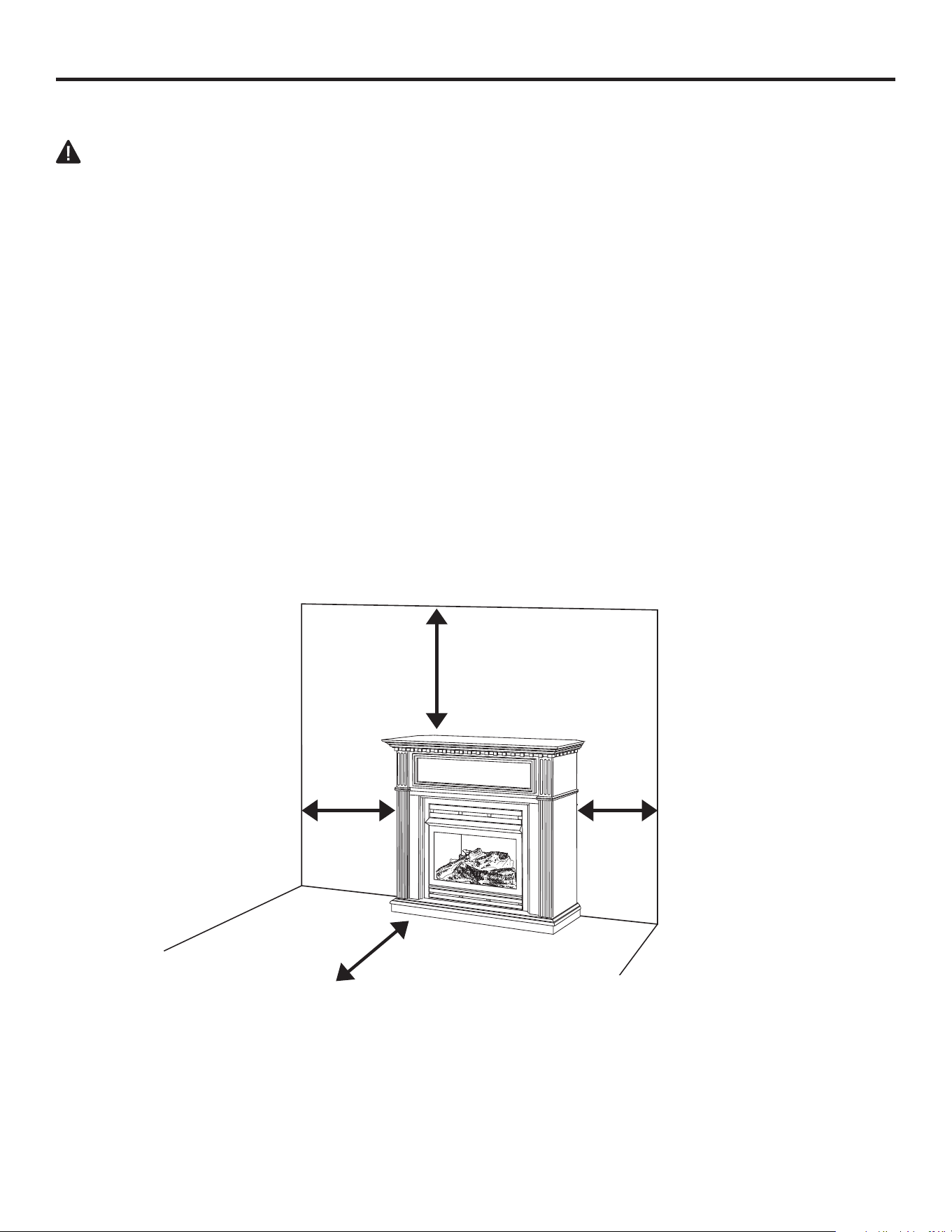
CLEARANCES TO COMBUSTIBLES
Carefully follow the instructions below. This heater is a designed to sit directly on the mantel base.
IMPORTANT: Maintain the minimum clearances shown in Figure 6 on page 12. If you can, provide
greater clearances from oor, ceiling and joining wall.
12
INSTALLATION
FIREPLACE CLEARANCES
CAUTION: If you install the replace in a home garage
• replace pilot and burner must be at least 18" above oor.
• locate replace where moving vehicle will not hit it.
For convenience and efciency, install replace
• where there is easy access for operation, inspection and service
• in coldest part of room
• If this appliance is to be installed directly on carpeting, tile or other combsutible material, other than
wood ooring, the appliance must be installed on a metal or wood panel extending the full width and
depth of the appliance.
An optional blower kit is available from your retailer. See Accessories, page 38. If planning to use
blower, follow instructions provided with blower for power source.
Minimum Clearances For Side Combustible Material, Side Wall and Ceiling
A. Clearances from the side of the replace cabinet to any combustible material and wall should
follow diagram in Figure 6.
B. Clearances from the top of the replace opening to the ceiling should not be less than 36".
6’’
Either
Side
Min.
36’’
Fig. 6 - Minimum Clearance to
Combustible Material
Min.
36''
36''
6''
Either
Side
6''
• This rebox is only for use with the mantel provided.
13
INSTALLATION
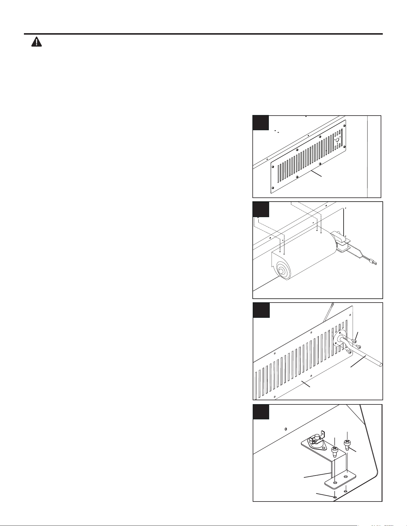
1. Remove Blower Access Panel.
FF
2. Mount Blower (B) onto bottom of
Fireplace Top using 4 screws (F).
3. Attach Power Cord (A) to Blower
Access Panel.
4. Attach Temperature Sensor (C) to
the Combustion Top using 2 sheet
metal screws.
1
2
3
Access Panel
Screws
Power Cord
Access Panel
WARNING: This optional blower is equipped with a three-prong (grounding) plug for
your protection against shock hazard and must be plugged directly into a properly
grounded three-prong receptacle.
Firebox must be disconnected from gas supply and removed from mantel before
installing fan accessory. Contact a qualied service person to do this.
BLOWER INSTALLATION (OPTIONAL)
4
Sheet
Metal
Screws
Senser
Bracket
Combustion Top
Mounting Holes
14
INSTALLATION
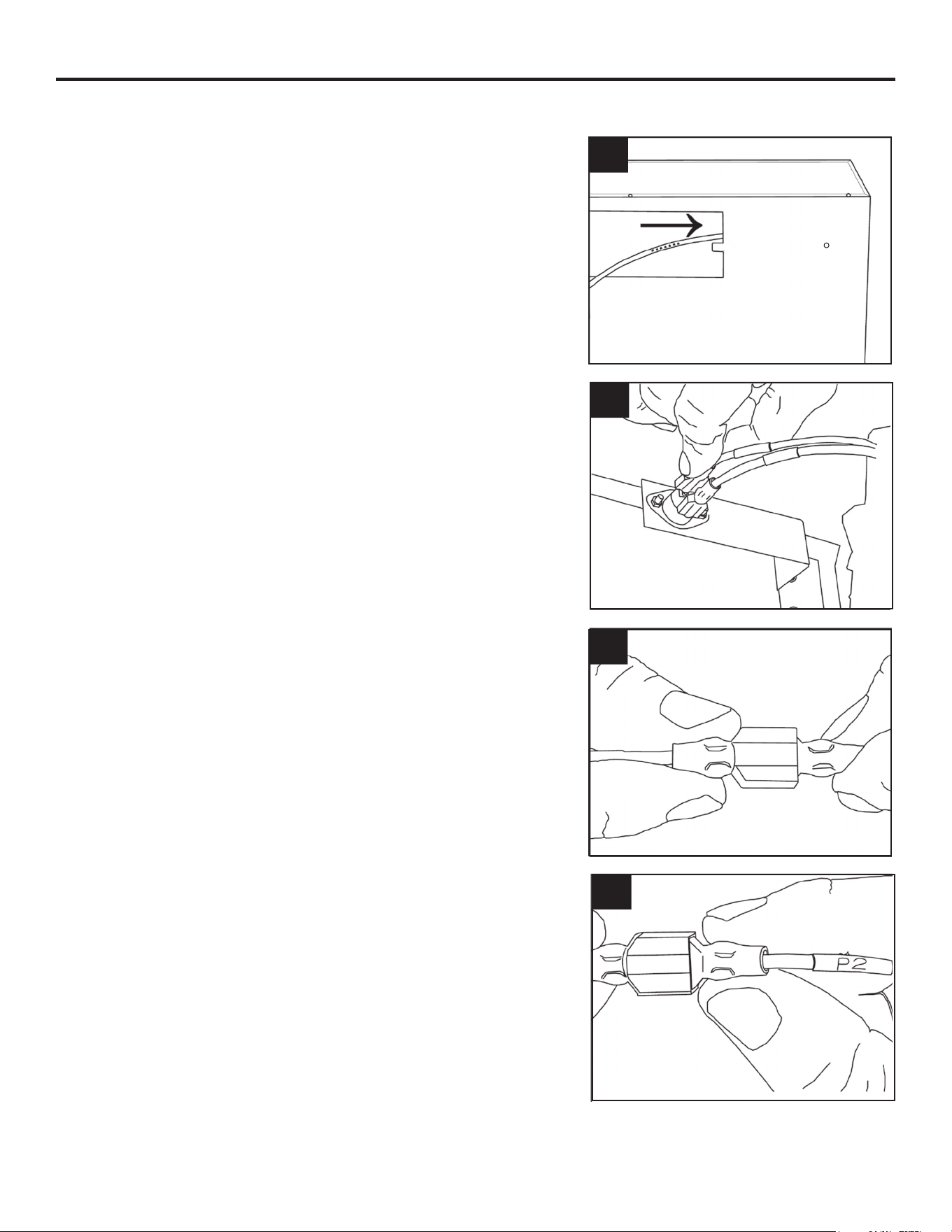
5. Important: Insert the wires marked
with AUTO, OFF and MAN into line
slot on the right corner. Keep wires
close to the bottom.
5
6. Insert two wires’ female plugs
marked with T1 and T2 (black and
yellow) into two male ports on
Temperature Sensor.
7. Insert the female plug on the white
power supply wire (marked with
P1), into the corresponding male
port (marked with P1).
6
7
8. Insert the female plug (marked
with P2) into the corresponding
male port, which is on the black
power supply wire (marked
with P2).
8
15
INSTALLATION
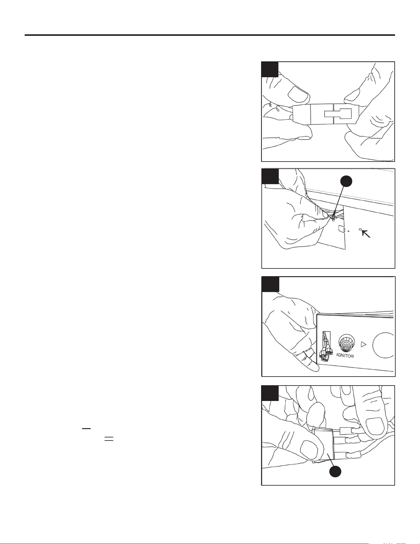
9. Insert the blower link (male plug)
into the power link (female port).
9
10. Important: Bind wires with cable
ties (G), and attach cable ties (G)
in holes on back of Outer Casing.
Attach one in hole near the top and
one in hole near the bottom.
10
11. Insert AUTO, OFF, MAN wires
through the Rocker Switch
opening.
11
12
Fixed
Hole
G
E
12. Connect AUTO, OFF, MAN wires
to the three corresponding male
ports on the Rocker Switch (E).
Match the "Auto" wire to the
symbol " " and the "Man" wire
to the symbol " " on the rocker
switch (E).
16
INSTALLATION
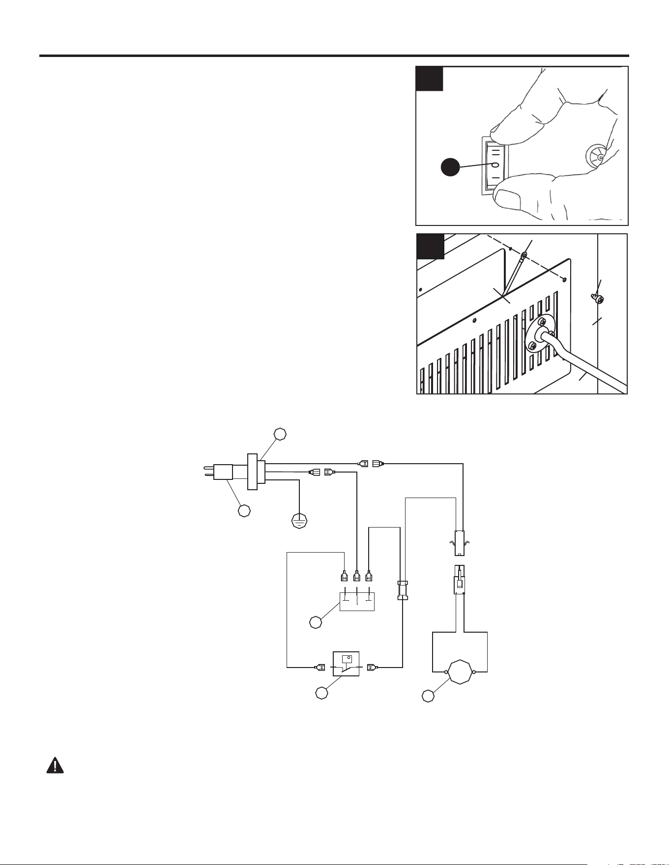
13. Push Rocker Switch (E) into
Control Panel and secure.
13
14. Check that all wires are secure
and reattach Blower Access Panel
to Outer Casing. Capture the
Green Ground wire between the
Access Plate and Outer Casing
with the upper right screw.
E
1
1
2
2
3
3
4
4
A A
B B
C C
D D
SHEET 1 OF 1
DRAWN
CHECKED
QA
MFG
APPROVED
dandowning
4/12/2013
DWG NO
Power Cord Attachment
TITLE
SIZE
C
SCALE
REV
Green Ground
Wire
14
Screw
Outer
Casing
Access Panel
Power Cord
t
WHITE
GREEN
RED
BLACK
BLACK
AUTO OFF
MAN
1
2
3
4
5
~120V
60Hz
1. Power Cord
2. Bushing Strain Relief
3. Blower
4. Temperature Sensor
5. Rocker Switch
FAN
Electrical Wiring Diagram
CAUTION: Label all wires prior to disconnection when servicing controls. Wiring errors can
cause improper and dangerous operation.
Verify proper operation after servicing.
NOTE: If any of the original wire as supplied with the appliance must be replaced, it must be
replaced with a wire of at least an equal temperature rating.
17
CONNECTING TO GAS SUPPLY
WARNING: A qualied service technician must connect heater to gas supply. Follow all local
codes.
CAUTION: Never connect heater directly to the gas supply. This heater requires an external
regulator (not supplied). The external regulator between the gas supply and heater must be installed.
Gas supplier provides external regulator for natural gas.
WARNING: Never connect heater to private (non-utility) gas wells. This gas is commonly known
as wellhead gas.
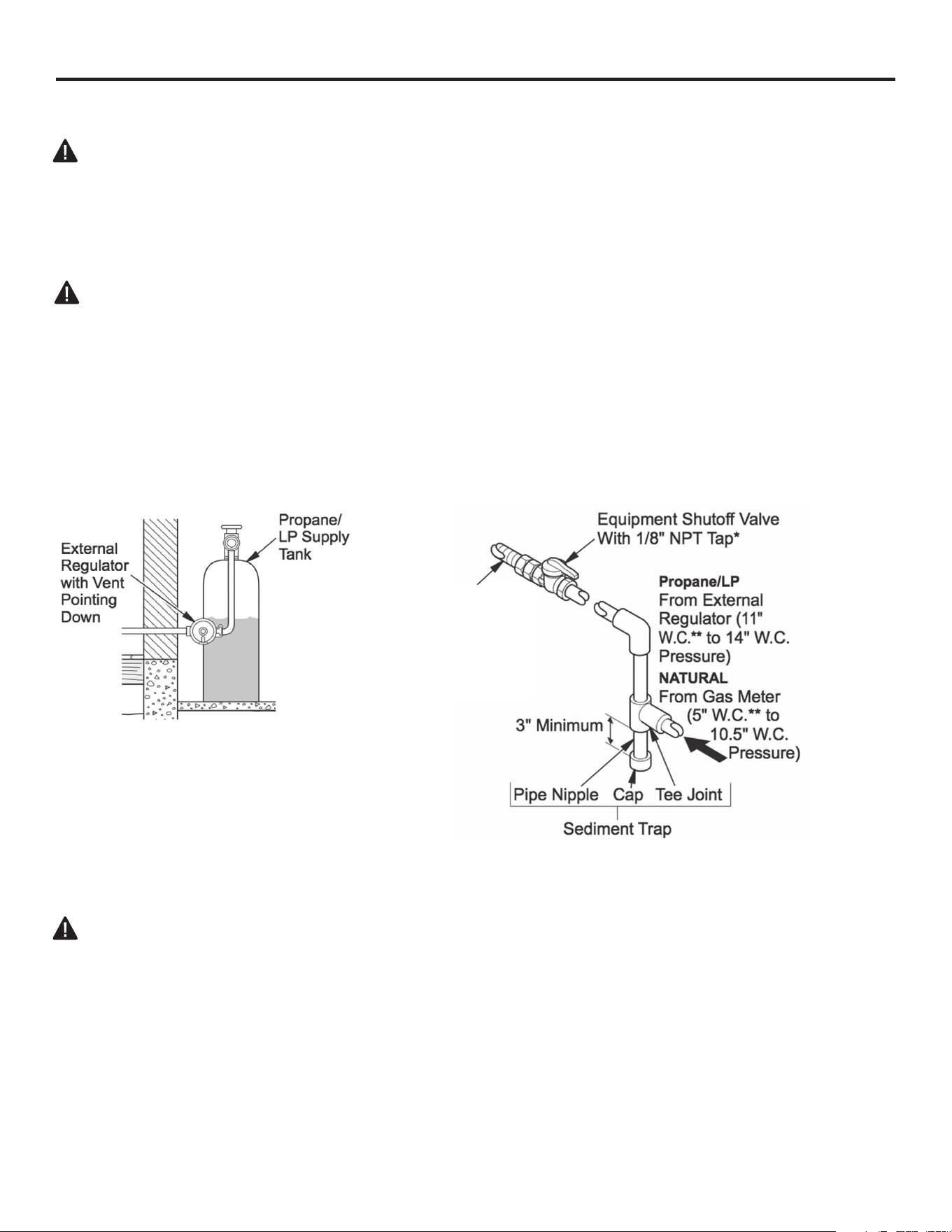
The installer must supply an external regulator for liquid propane. The external regulator is
provided by the gas supplier for natural gas. The external regulator will reduce incoming gas pres-
sure. You must reduce incoming gas pressure to between 11 and 14 in. of water column for propane
and between 5 and 10.5 in. of water column for natural gas. If you do not reduce incoming gas pres-
sure, heater regulator damage could occur. Install external regulator with the vent pointing down as
shown in Fig. 6. Pointing the vent down protects it from freezing rain or sleet.
* Purchase the optional equipment shutoff valve from your local Home Center store.
INSTALLATION
CAUTION: Use only new black iron or steel pipe. Internally tinned copper tubing
may be used in certain areas. Check your local codes. Use pipe of ½ in. diameter
or greater to allow proper volume gas to heater. If pipe is too small, loss of pressure
will occur. Installation must include an equipment shutoff valve, union, and plugged
1/8-in. NPT tap. Locate NPT tap within reach for test gauge hook up. NPT tap must
be upstream from heater (See Fig. 10).
IMPORTANT: Install equipment shutoff valve in an accessible location. The equipment
shutoff valve is for turning on or shutting off the gas to the appliance. Apply pipe joint
sealant lightly to male threads. This will prevent excess sealant from going into pipe.
Excess sealant in pipe could result in clogged heater valves.
Approved
Flexible
Gas Line
or 1/2''
Black Pipe
Fig. 9 - Regulator Conversion
Fig. 10 - Gas Connection
18
INSTALLATION
Installation Items Needed (Not Provided)
Regulator
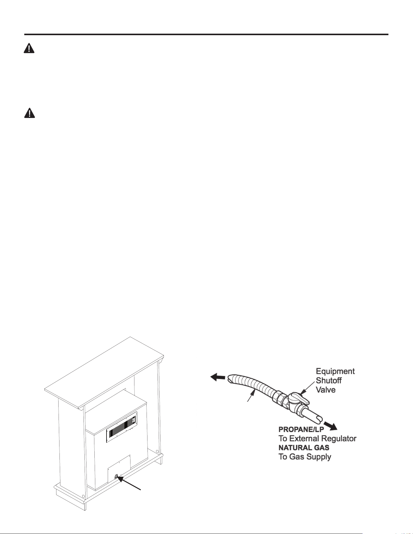
Fig. 11 - Attaching Flexible Gas Line
to Equipment Shutoff Valve
Flexible Gas Line
or Black Pipe to
Fireplace Cabinet
Regulator
To Regulator
• 8'' Adjustable Wrench
• 8'' Pipe Wrench
• Flexible Gas Line (24'' Min.) or 1/2'' Black Pipe
• 90 Deg. 3/8 NPT x 3/8'' Flare Fitting or 3/8'' Street Elbow
• Sealant (Resistant to Propane (LP) Gas)
• Shut Off Valve
1) A variety of options are possible for routing the Gas Connection Lines depending on where
your Gas Supply line is located. Install the 3/8'' Fitting to the Fireplace Cabinet Regulator
using Sealant and direct the attachment and either left or right toward the Gas Supply Line.
2) Install the Gas Line to the 90 Deg. tting and attach to the Shut Off Valve. It may be
necessary to cut and access hole in the side or bottom of the Mantel Cabinet depending on
your particular connection.
3) Check all connections for gas leaks.
NOTICE: Most building codes do not permit concealed gas connections. Check
your local building code prior to using a Flexible Gas Line for this installation.
CAUTION: Use pipe joint sealant that is resistant to gas (PROPANE or NG). We
recommend that you install a sediment trap in a supply line as shown in Fig. 10.
Locate sediment trap where it is within reach for cleaning and not likely to freeze.
Install in the piping system between fuel supply and heater. A sediment trap traps
moisture and contaminants. This keeps them from going into heater controls. If
sediment trap is not installed or is installed incorrectly, heater may not run properly.
CAUTION: Avoid damage to regulator. Hold gas regulator with wrench when
connecting into gas piping and/or ttings. NG Models: 5 in. to 10.5 in. W.C. Gas
supplier provides external regulator for natural gas.
19
VFF-PH(20NGB)(20NG)(20NG-C1)(20NG-2T1)
VFF-PH(20LPB)(20LP)(20LP-C2)(20LP-2T2)
VFF-PH(26NG)(26NG-T1)(26NG-2H1)
VFF-PH(26LP)(26LP-T2)(26LP-2H2)
WARNING:
Failure to position the parts in accordance with these diagrams or failure to use only parts
specically approved with this heater may result in property damage or personal injury.
CAUTION: After installation and peridically thereafter, check to ensure that no yellow ame comes in
contact with any log. With the heater set to High, check to see if yellow ames contact any log. If so,
reposition logs according to the log installation instructions in this manual. Yellow ames contacting
logs will create soot.
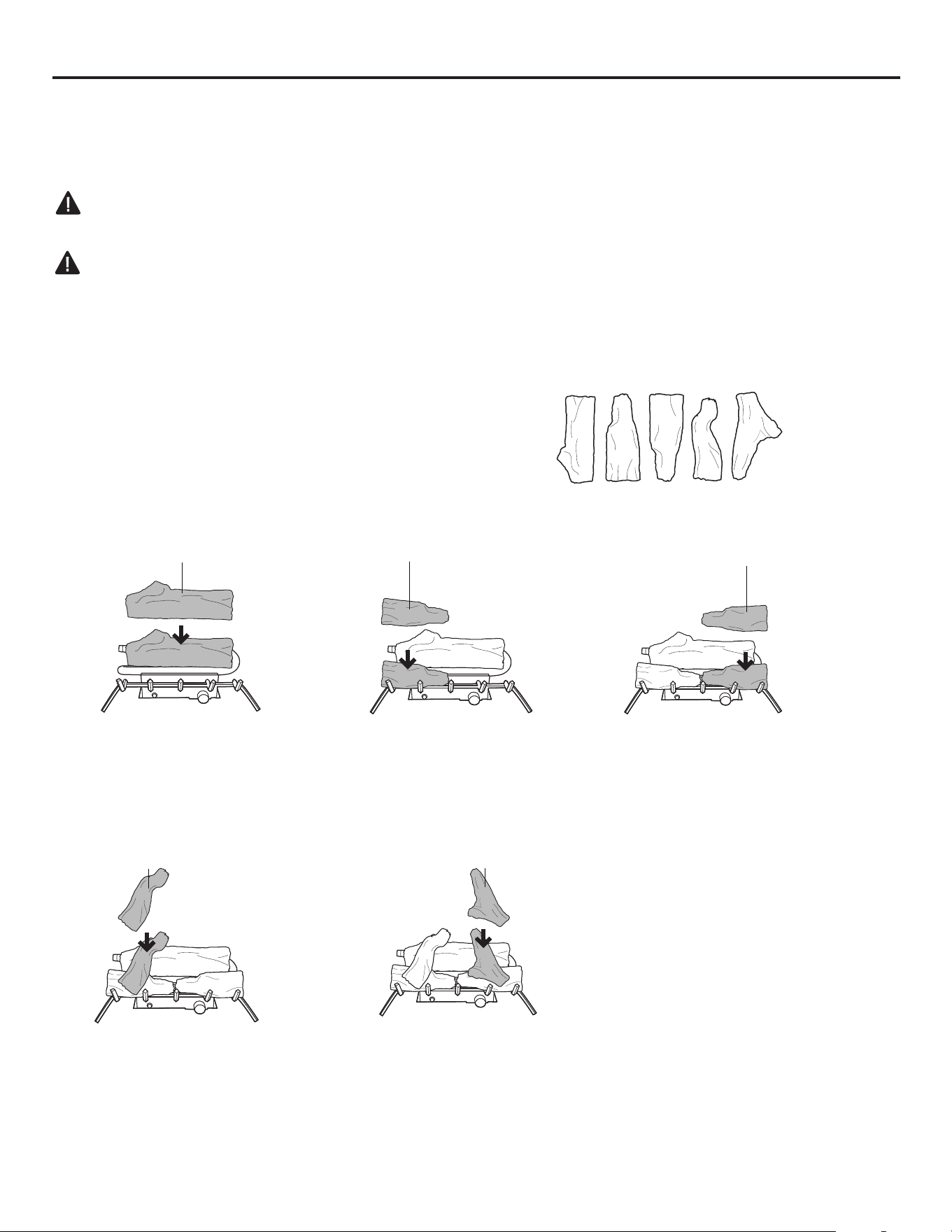
It is very important to install the logs
exactly as instructed. Do not modify logs.
Use only logs supplied with heater.
Each log is marked with a number.
this number will help you identify the logs
when installing.
Provided Logs: 5
Installing Log #1 Installing Log #2 Installing Log #3
2
1
3
1. Insert log #1 onto the
rear row of pins on the
base pan.
2. Insert log #2 onto the
front left pin on the base
pan.
3. Insert log #3 onto the
front right pin on the base
pan.
Installing Log #4 Installing Log #5
4
5
4. Insert log #4 onto the left
pin of log #1 and the pin of
log #2.
5. Insert log #5 onto the
right pin of log #1 and the
pin of log #3.
1
2 3 4 5
ASSEMBLING LOGS
20
VFF-PH(32NGB)(32NG)(32NG-H1)(32NG-2C1)
VFF-PH(32LPB)(32LP)(32LP-H2)(32LP-2C2)
WARNING:
Failure to position the parts in accordance with these diagrams or failure to use only parts
specically approved with this heater may result in property damage or personal injury.
CAUTION: After installation and peridically thereafter, check to ensure that no yellow ame comes in
contact with any log. With the heater set to High, check to see if yellow ames contact any log. If so,
reposition logs according to the log installation instructions in this manual. Yellow ames contacting
logs will create soot.
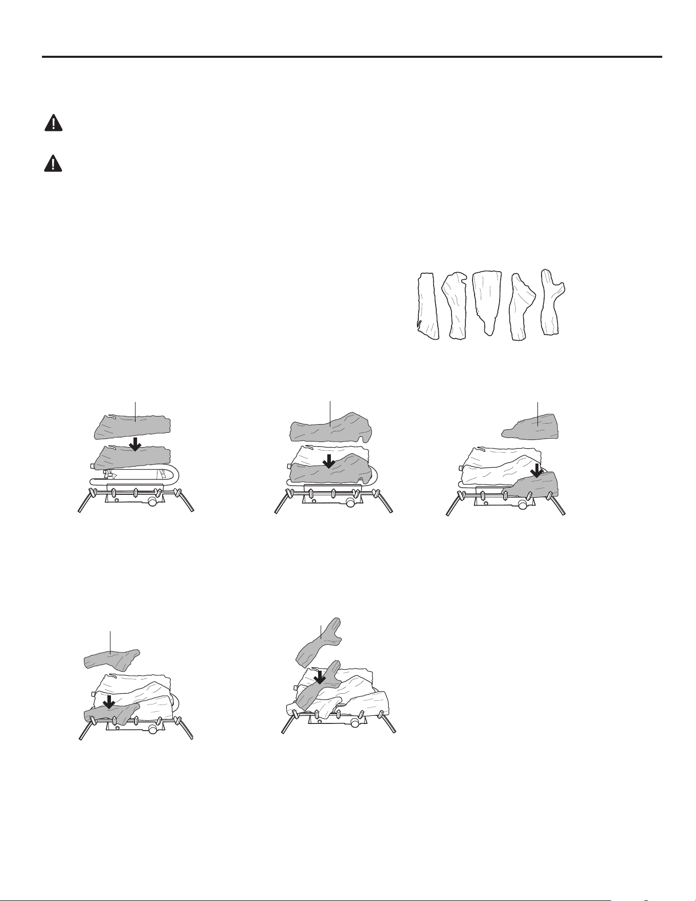
It is very important to install the logs
exactly as instructed. Do not modify logs.
Use only logs supplied with heater.
Each log is marked with a number.
this number will hep you identify the logs
when installing. After installing logs, add
decorative cinders around the grate base,
do not place any decorative cinders on
logs or burner.
Provided Logs: 5
Installing Log #1 Installing Log #2 Installing Log #3
2
1
4
1. Insert log #1 onto the
rear brackets of the base
pan.
2. Insert log #2 onto the
middle row of pins on the
base pan.
4 . Insert log #4 onto the
front left pin of the base
pan.
Installing Log #4 Installing Log #5
3
5
3. Insert log #3 onto the
front right pin of the base
pan.
5. Insert log #5 onto the
left pins of log #1 & #2 and
the pin of log #3.
ASSEMBLING LOGS
4
3
5
41 2 3
21
CHECKING GAS CONNECTIONS
WARNING: Test all gas piping and connections for leaks after installing or servicing. Correct all
leaks immediately.
WARNING: Never use an open ame to check for a leak. Apply a mixture of liquid soap and water
to all joints. If bubbles form, there may be a leak. Correct all leaks immediately.
Pressure Testing Gas Supply Piping System
Test Pressures In Excess Of 1/2 PSIG ( 3.5kPa )
1. Disconnect heater with its appliance main gas valve (control valve) and equipment shutoff valve
from gas supply piping system. Pressures in excess of 1/2 PSIG will damage heater regulator.
2. Cap off open end of gas pipe where equipment shutoff valve was connected.
3. Pressurize supply piping system by either using compressed air or opening gas supply tank valve.
4. Check all joints of gas supply piping system. Apply mixture of liquid soap and water to gas joints. If
bubbles form, there may be a leak.
5. Correct all leaks immediately.
6. Reconnect heater and equipment shutoff valve to gas supply. Check reconnected ttings for leaks.
Test Pressures Equal To or Less Than 1/2 PSIG (3.5 kPa)
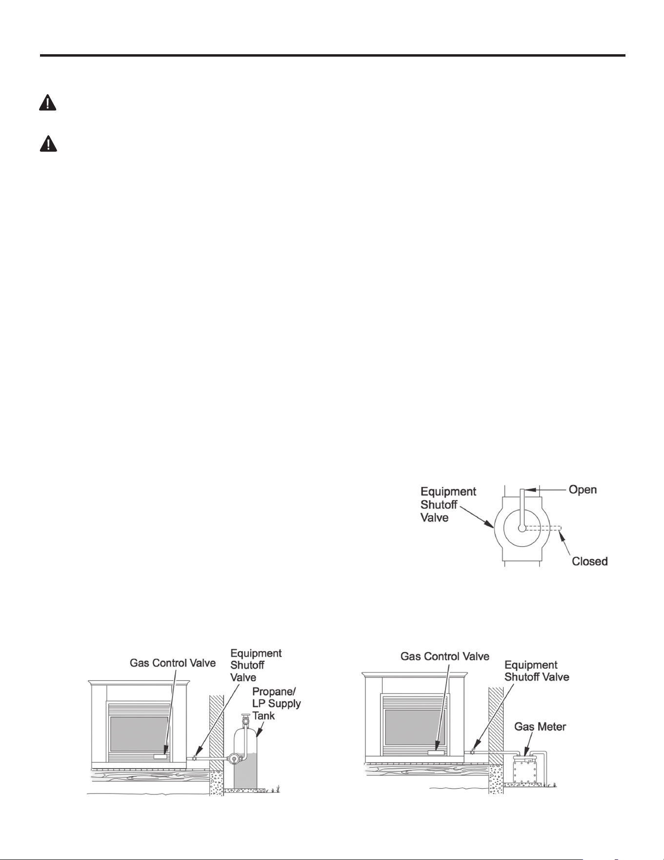
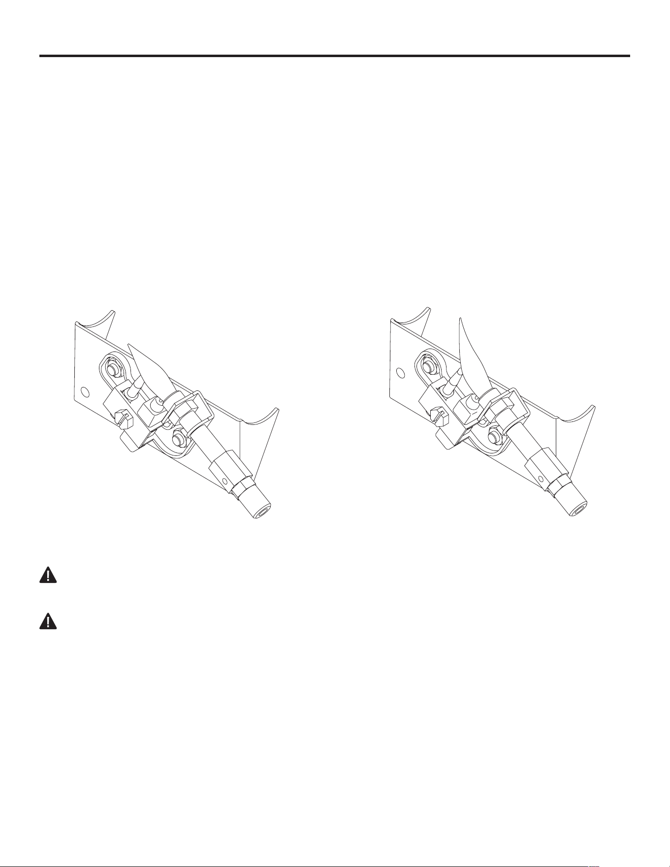
1. Close equipment shutoff valve (See Fig. 12).
2. Pressure supply piping system by either using compressed air or opening gas supply tank valve.
3. Check all joints from gas meter to equipment shutoff valve (See Fig.13). Apply mixture of liquid
soap and water to gas joints. If bubbles form, there may be a leak.
4. Correct all leaks immediately.
Pressure Testing Heater Gas Connections
1. Open equipment shutoff valve (See Fig. 12).
2. Open gas supply tank valve.
3. Make sure control knob of heater is in the OFF position.
4. Check all joints from equipment shutoff valve to control valve
(See Fig. 13). Apply mixture of liquid soap and water to gas joints.
If bubbles form, there may be a leak.
5. Light heater (see Operation, page 23).
Check all other internal joints for leaks.
6. Turn off heater (see "To Turn Off Gas to Appliance," page 24).
INSTALLATION
Fig. 13 - Checking Gas Joints
(Propane/LP Only)
Fig. 12 - Equipment Shutoff Valve
Fig. 14 - Checking Gas Joints
(Natural Gas Only)
22
OPERATION
FOR YOUR SAFETY
READ BEFORE LIGHTING
WARNING: If you do not follow these instructions exactly, a re or explosion may result
causing property damage, personal injury or loss of life.
A. This appliance has a pilot which must be lighted by the electronic ignitor. When lighting the pilot,
follow these instructions exactly.
B. BEFORE LIGHTING smell all around the appliance area for gas. Be sure to smell next to the oor
because some gas is heavier than air and will settle on the oor.
WHAT TO DO IF YOU SMELL GAS
• Do not try to light any appliance.
• Do not touch any electrical switch; do not use any phone in your building.
• Immediately call your gas supplier from a neighbor’s phone. Follow the gas supplier’s instructions.
• If you cannot reach your gas supplier, call the re department
C. Use only your hand to push in or turn the gas control knob. Never use tools. If the knob will not
push in or turn by hand, don’t try to repair it, call a qualied service technician. Forced or attempted
repair may result in re or explosion.
D. Do not use this appliance if any part has been under water. Immediately call a qualied service
technician to inspect the appliance and to replace any part of the control system and any gas control
which has been under water.
LIGHTING INSTRUCTIONS
1. STOP! Read the safety information as noted above.
2. Open the lower access panel located below the replace screen.
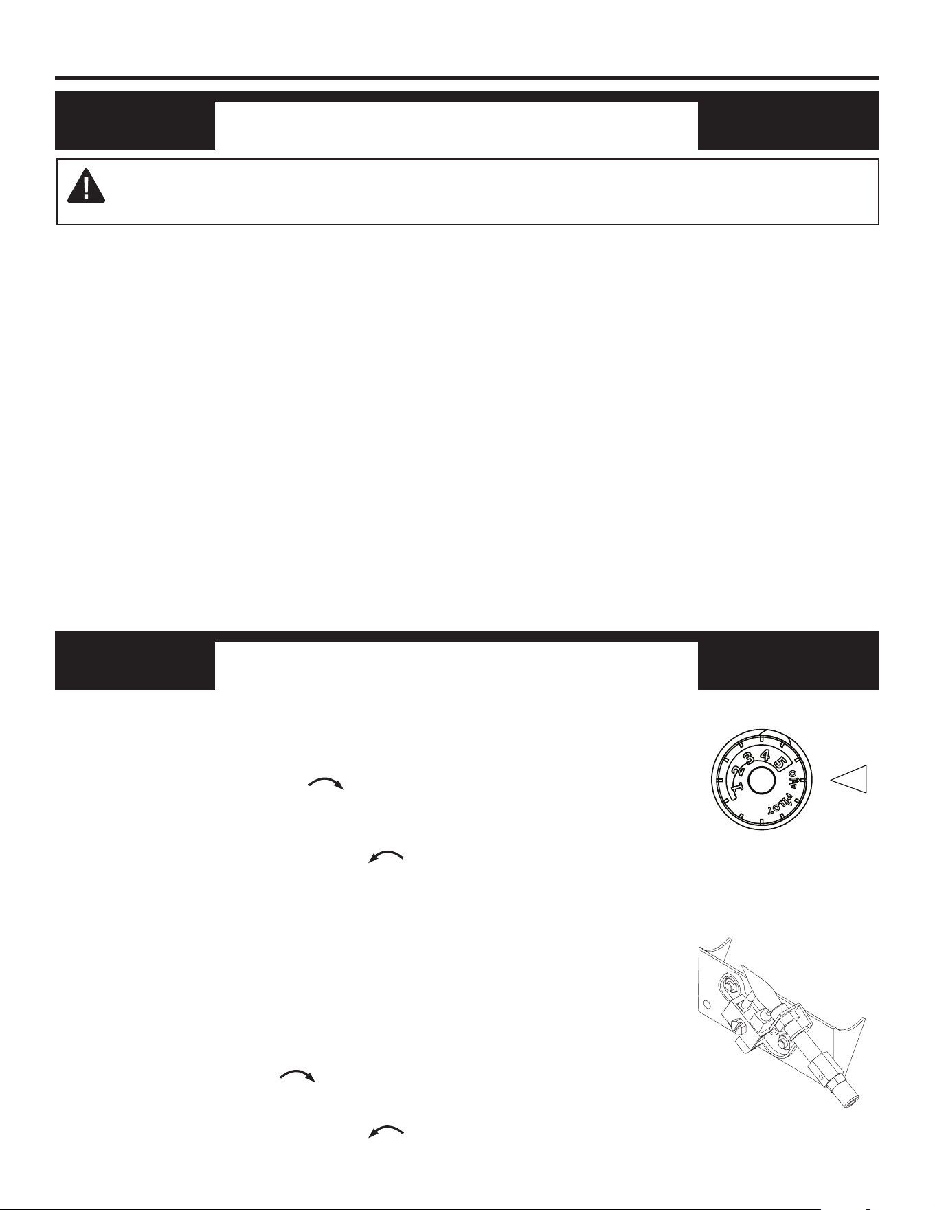
3. Turn control knob clockwise to the “OFF” position (See Fig. 15).
4. Wait ve (5) minutes to clear out any gas. Then smell for gas, including
near the oor. If you smell gas, STOP! Follow “B” in the safety informa-
tion as noted above. If you don’t smell gas, go to the next step.
5. Turn control knob counterclockwise to the “PILOT” position (See
Fig. 16). Depress control knob.
6. With control knob depressed, push down on the ignitor button until the
pilot lights. The pilot is located behind the replace screen, centered
near the rear of the burner.
7. Keep control knob depressed for (30) seconds after pilot lights. Release
control knob.
• If the control knob does not pop up when released, stop and immediately
call a qualied service technician or gas supplier.
• If pilot goes out repeat steps 3 through 7. Wait (1) minute before attempt-
ing to light pilot again. If after several tries the pilot still goes out, turn the
gas control knob clockwise to the “OFF” position and call a qualied
service technician.
8. Turn control knob counterclockwise to desired setting.
9. Close lower access panel.
Fig. 15 - Control Knob
Fig. 16 - Pilot
Models VFF-PH(20NGB)(20NG)(20NG-C1)(20NG-2T1), VFF-PH(20LPB)(20LP)(20LP-C2)(20LP-2T2)
VFF-PH(26NG)(26NG-T1)(26NG-2H1), VFF-PH(26LP)(26LP-T2)(26LP-2H2)
23
OPERATION
Models VFF-PH(32NGB)(32NG)(32NG-H1)(32NG-2C1)
VFF-PH(32LPB)(32LP)(32LP-H2)(32LP-2C2)
1. STOP! Read the safety information on the page before this.
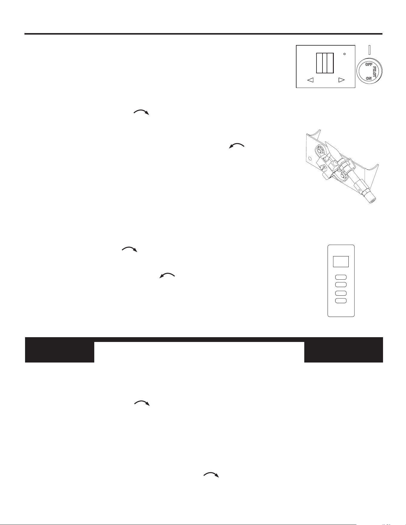
2. Open the lower access panel located below the replace screen.
• Set receiver switch to “ON” position (See Fig. 17).
3. Turn control knob clockwise to the “OFF” position (See Fig. 17).
4. Wait ve (5) minutes to clear out any gas. Then smell for gas, including
near the oor. If you smell gas, STOP! Follow “B” in the safety information
on the page before this. If you don’t smell gas, go to the next step.
5. Push in slightly and turn control knob counterclockwise to the
“PILOT” position (See Fig. 17). Depress control knob.
6. With control knob depressed, push down on the ignitor button until the
pilot lights. The pilot is located behind the replace screen, centered near
the rear of the burner (See Fig. 18).
7. Keep control knob depressed for (30) seconds after pilot lights. Release
control knob.
• If the control knob does not pop up when released, stop and immediately
call a qualied service technician or gas supplier.
• If pilot goes out repeat steps 3 through 7. Wait (1) minute before attempting
to light pilot again. If after several tries the pilot still goes out, turn the
gas control knob clockwise to the “OFF” position and call a qualied
service technician.
8. Turn control knob counterclockwise to the “ON” position.
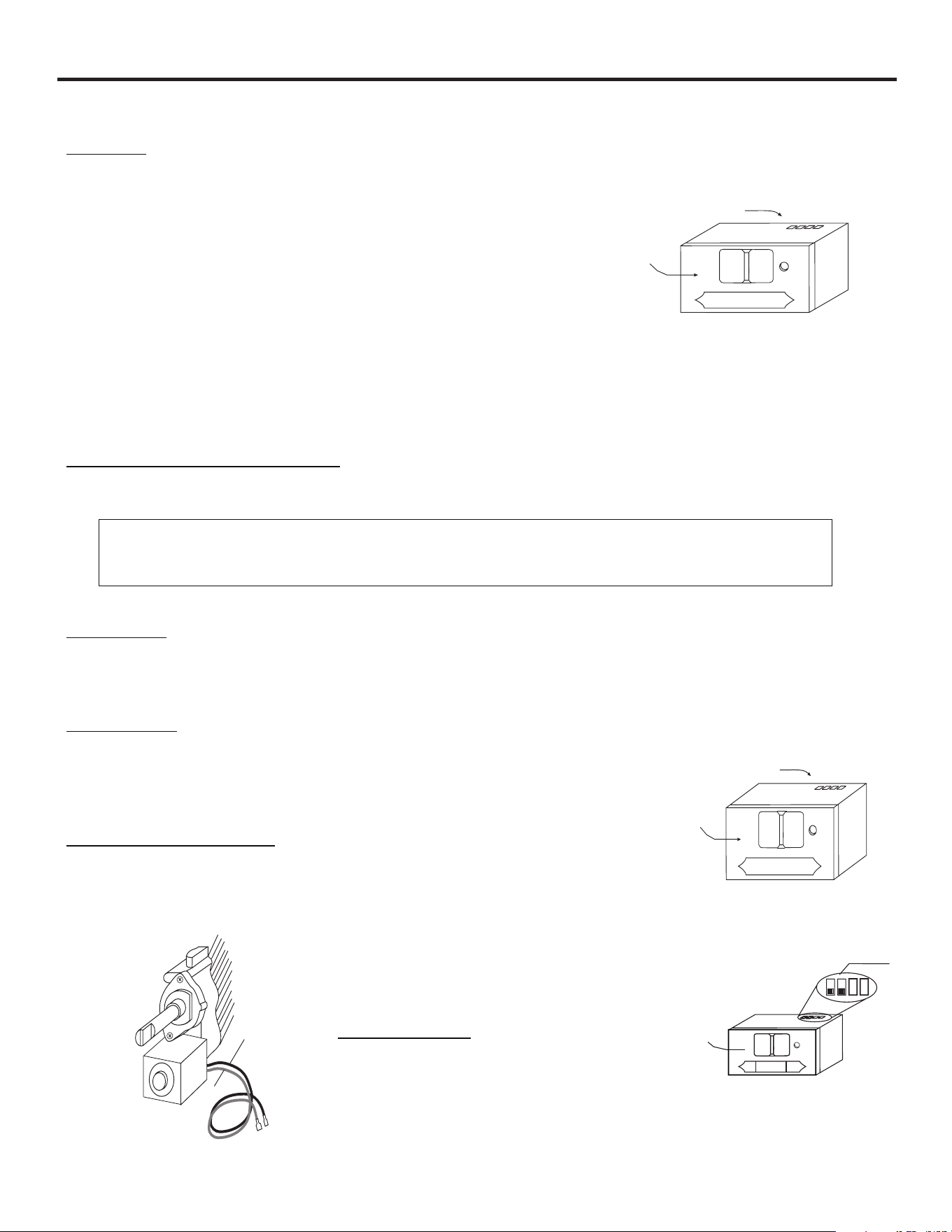
9. To use the included thermostatic remote control, set receiver switch to
the “REMOTE” position (See Fig. 19). Press the ON button to turn on the
remote to ignite the main burner. Refer to the remote control instruction
manual on the next page for “MODE” and “SET” functions.
ONOFF
REMOTE
LEARN
TO TURN OFF GAS TO APPLIANCE
Models VFF-PH(20NGB)(20NG)(20NG-C1)(20NG-2T1), VFF-PH(20LPB)(20LP)(20LP-C2)(20LP-2T2)
VFF-PH(26NG)(26NG-T1)(26NG-2H1), VFF-PH(26LP)(26LP-T2)(26LP-2H2)
1. Open the lower access panel located under the replace screen.
2. Turn control knob clockwise to the “OFF” position.
3. Close lower access panel.
Models VFF-PH(32NGB)(32NG)(32NG-H1)(32NG-2C1), VFF-PH(32LPB)(32LP)(32LP-H2)(32LP-2C2)
1. Set thermostat to the lowest setting.
2. Press the OFF button on the remote control.
3. Open the lower access panel located under the replace screen.
4. Push in slightly and turn control knob clockwise to the “OFF” position.
5. Close lower access panel.
Fig. 17 - Receiver
& Control Knob
ON
OFF
MODE
SET
Fig.19 - Remote
Fig. 18 - Pilot
24
REMOTE CONTROL OPERATION
MULIT-FUNCTION WIRELESS REMOTE CONTROL SYSTEM
FOR OPERATING A LATCHING SOLENOID VALVE, MANUALLY OR WITH A THERMOSTAT FUCTION
INTRODUCTION
This remote control system was developed to provide a safe, reliable, and user-friendly remote control system for gas heating
appliances. The system is operated manually from the transmitter. The system operates on radio frequencies (RF) within a 20-feet
range using non-directional signals. The system operates on one of 1,048,576 security codes that are programmed into the transmitter
at the factory; the remote receiver's code must be matched to that of the transmitter prior to initial use.
Review COMMUNICATION SAFETY under GENERAL INFORMATION section. This safety feature shuts down
the appliance when a potentially unsafe condition exists.
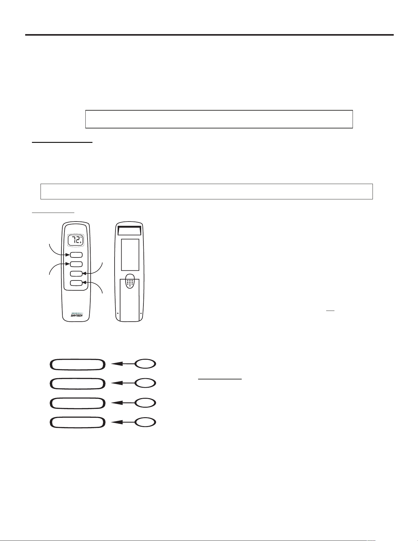
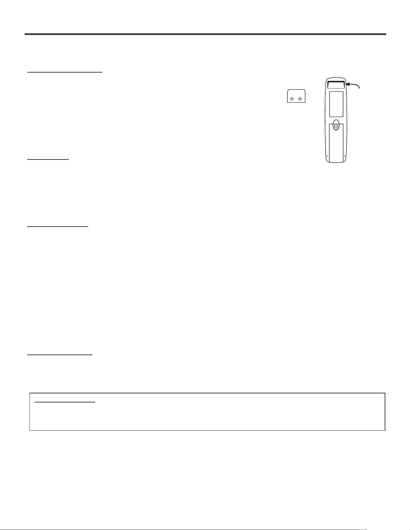
TRANSMITTER
This remote control SYSTEM offers the user a battery-operated remote control to
power a latching solenoid such as those used with gas valves used in some
heater rated gas logs, gas fireplaces and other gas heating appliances.
The solenoid circuit uses the battery power from the receiver to operate a
solenoid. The circuit has reversing polarity software which reverses the positive
(+) and negative (-) output of the receiver's battery power to drive a latching
solenoid ON/OFF. The SYSTEM is controlled by the remote transmitter.
The transmitter operates on a (2) 1.5V AAA batteries.
ALKALINE batteries should always be used for longer battery life and maximum
operational performance. Re-chargeable batteries should not be used.
Before using the transmitter, install the (2) AAA transmitter batteries into the
battery compartment. (Use caution that batteries are installed in the proper
direction)
KEY SETTINGS
ON - Operates unit to on position, Manually operated solenoid ON.
OFF - Operates unit to off position, Manually operated solenoid OFF.
MODE - Changes unit from manual mode to thermo mode.
SET - Sets temperature in thermo mode.
ON
MODE
OFF
SET
1
2
3
4
ON
MODE
OFF
BUTTON
WALL CLIP
SLOT
BATTERY
COMPARTMENT
FRONT BACK
OFF
SET
ON
BUTTON
MODE
BUTTON
SET
BUTTON
IF YOU CANNOT READ OR UNDERSTAND THESE INSTALLATION INSTRUCTIONS DO NOT
ATTEMPT TO INSTALL OR OPERATE
25
REMOTE CONTROL OPERATION
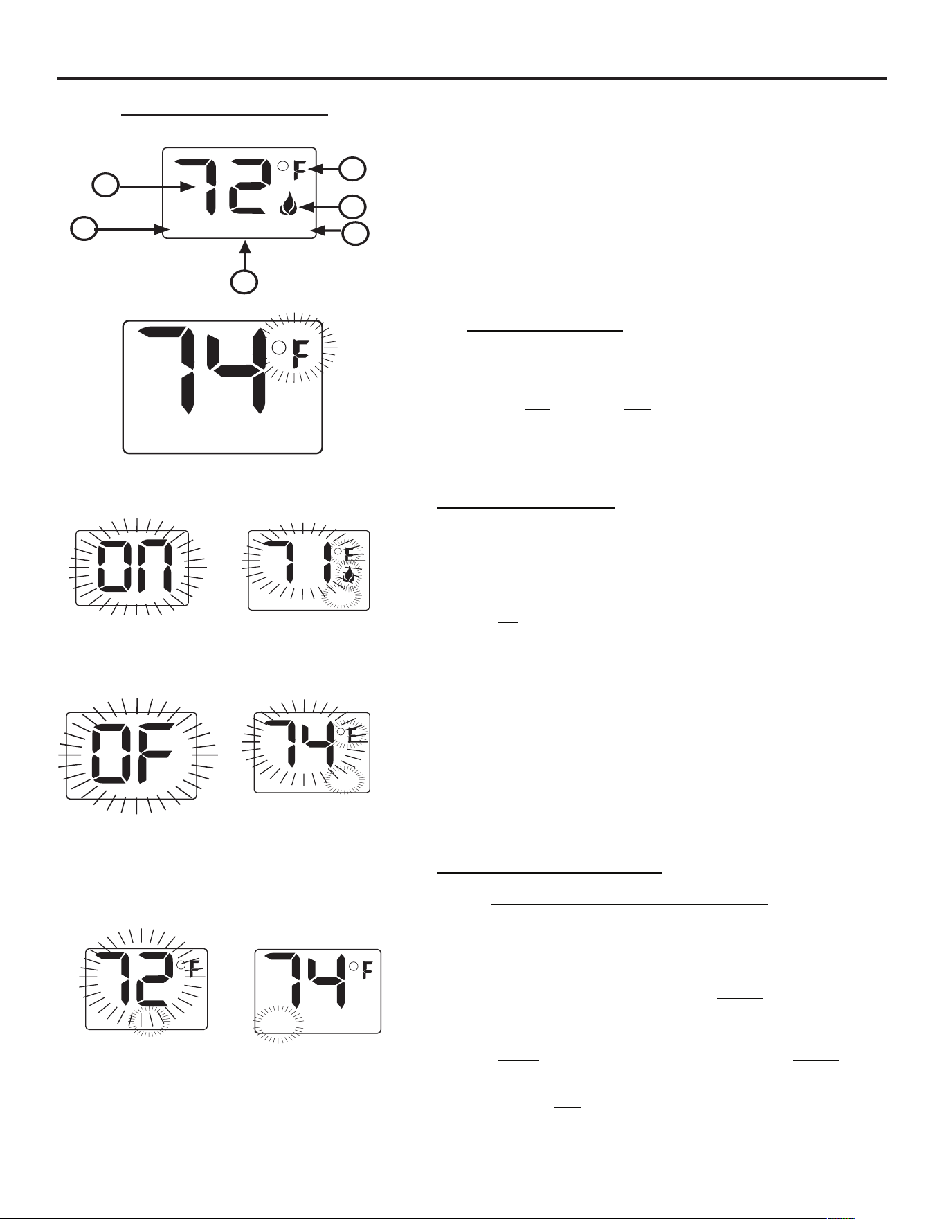
1. DISPLAY Indicates CURRENT room temperature .
2.
0
F OR
0
C Indicates degrees Fahrenheit or Celsius.
3. FLAME Indicates burner/valve in operation.
4. ROOM Indicates remote is in THERMO operation.
5. TEMP Appears during manual operation.
6. SET Appears during time the of setting the desired
temperature in the thermo operation.
SETTING
0
F /
0
C SCALE
The factory setting for temperature is
0
F. To change this setting to
0
C,
first
• Press the ON key and the OFF key on the transmitter at the same
time this will change from
0 F
to
0 C
. Follow this same procedure to
change from
0
C back to
0
F.
MANUAL FUNCTION
To operate the system in the manual “MODE” do the following.
ON OPERATION
Press the ON key the appliance flame will come on. During this time the
LCD screen will show ON, after 3 seconds the LCD screen will default
to display room temperature and the word TEMP will show. (Flame icon
wil appear on LCD screen in manual on mode)
OFF OPERATION
Press the OFF key the appliance flame will shut off. During this time the
LCD screen will show OF, after 3 seconds the LCD screen will default to
display room temperature and the word TEMP will show.
THERMOSTAT FUNCTION
SETTING DESIRED ROOM TEMPERATURE
When used as a vented decorative appliance, use of the thermostat
function is prohibited, operate manually only.
This remote control system can be thermostatically controlled when the
transmitter is in the THERMO mode (The word ROOM must be
displayed on the screen). To set the THERMO MODE and DESIRED
room temperature,
Press the MODE key until the LCD screen shows the word ROOM, then
the remote is in the thermostatic mode.
Press and hold the SET key until the desired set temperature is
reached. (By pressing and holding the set key the LCD screen set
numbers will increase from 45
0
to 99
0
then restart over at 45
0
) Next
TEMP
TEMPSET
THERMO SET
SCREEN WHILE
DEPRESSING OFF
KEY
TEMP
SCREEN AFTER 3
SECOND DEFAULT
ROOM
TEMP
THERMO MODE
TEMP
SCREEN AFTER 3
SECOND DEFAULT
ROOM
LCD - Liquid Crystal Display
TEMP
1
2
3
SET
4
5
6
SCREEN WHILE
DEPRESSING ON
KEY
26
REMOTE CONTROL OPERATION
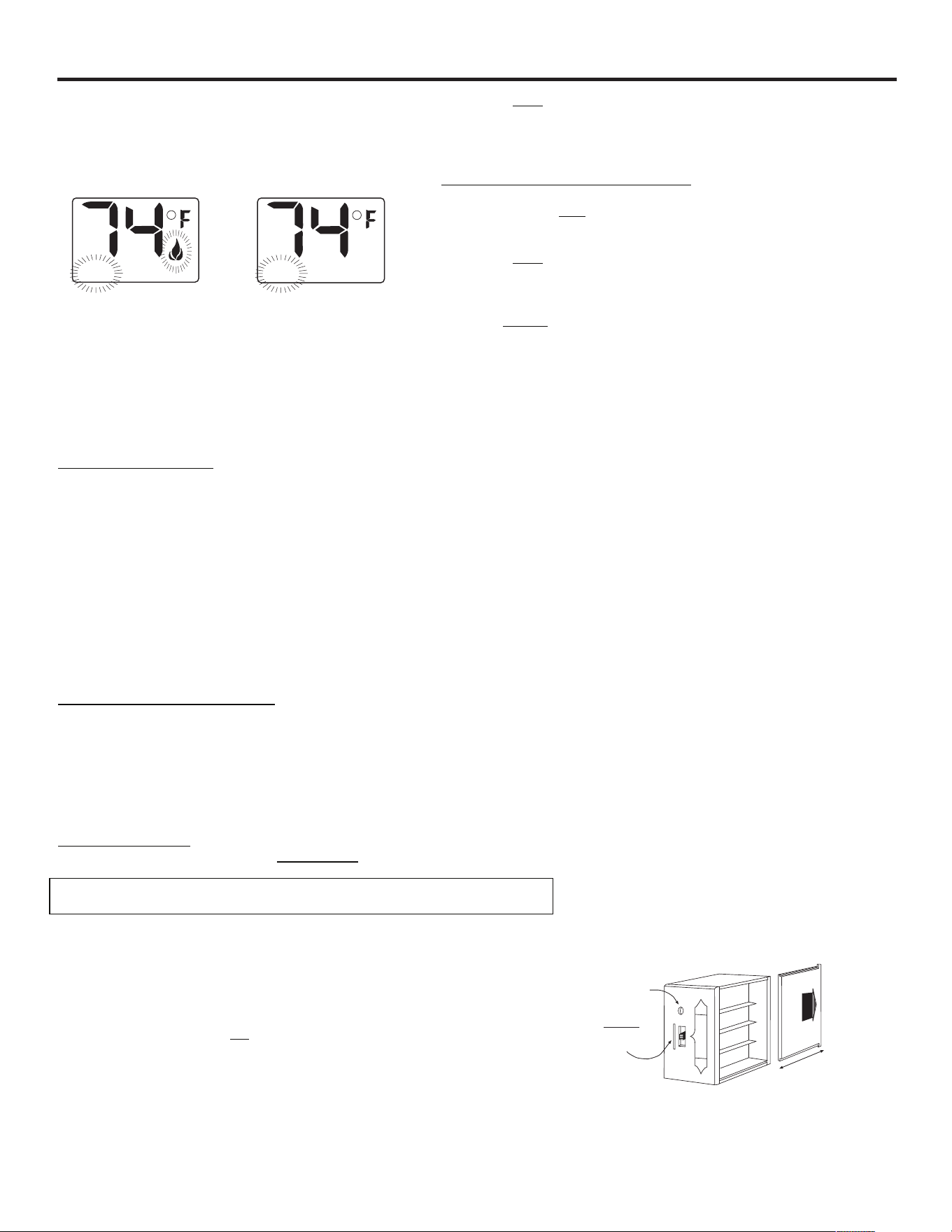
release the SET key. The LCD screen will display the set temperature
for 3 seconds and the LCD screen will flash the set temperature for 3
seconds, then the LCD screen will default to display the room
temperature.
TO CHANGE THE SET TEMPERATURE
Press and hold the SET key until the desired set temperature is
reached. (By pressing and holding the set key the LCD screen set
numbers will increase from 45
0
to 99
0
then restart over at 45
0
) Next
release the SET key. The LCD screen will display the set temperature
for 3 seconds, then will flash the set temperature for 3 seconds, then the
LCD screen will default to display the room temperature.
Press the MODE key to disengage the thermo mode. The word ROOM
on the LCD screen will not show when the thermo is not in operation.
NOTE: The highest SET temperature is 99
0
Fahrenheit (32
0
Celsius)
and the lowest temperature is (45
0
Fahrenheit (6
0
Celsius)
OPERATIONAL NOTES:
The Thermo Feature on the transmitter operates the appliance whenever the ROOM TEMPERATURE varies a certain number of
degrees from the SET TEMPERATURE. This variation is called the “SWING” or TEMPERATURE DIFFERENTIAL. The normal
operating cycle of an appliance may be 2-4 times per hour depending on how well the room or home is insulated from the cold or drafts.
The factory setting for the “swing number” is 2. This represents a temperature variation of +/- 2
0
F (1
0
C) between SET temperature
and ROOM temperature, which determines when the fireplace will be activated.
The transmitter has ON and OFF manual functions that are activated by pressing either button on the face of the transmitter. When a
button on the transmitter is pressed the word ON or OF will appear on the LCD screen to show while the signal is being sent. Upon
initial use, there may be a delay of three seconds before the remote receiver will respond to the transmitter. This is part of the system's
design.
POWER SETTING – CON 1001 TH
The electronics in the remote control system have the capability of "powering" two different types of DC-powered components. If any
operational problems are noted, contact Customer Service.
The RECEIVER comes from the factory programmed to provide pulse DC voltage (5.5 VDC to 6.3 VDC) to a latching solenoid.
REMOTE RECEIVER
IMPORTANT
THE REMOTE RECEIVER SHOULD BE POSITIONED WHERE AMBIENT
TEMPERATURES DO NOT EXCEED 130° F.
The remote receiver (right) operates on (4) 1.5V AA-size batteries. It is
recommended that ALKALINE batteries be used for longer battery life and maximum
microprocessor performance. IMPORTANT: New or fully charged batteries are
essential to proper operation of the remote receiver as a latching solenoid power
consumption is substantially higher than standard remote control systems. Re-
chargeable batteries should not be used.
NOTE: The remote receiver will only respond to the transmitter when the 3-position
slide button on the remote receiver is in the REMOTE position. The remote receiver
houses the microprocessor that responds to commands from the transmitter to
control system operation.
ROOM
TEMP
THERMO ON
ROOM
TEMP
THERMO OFF
REMOTE
ON
OFF
LEARN
Requires 4-AA 1.5V
alkaline batteries
Learning
button
Remote Receiver
Battery cover slides on/off
Slide
Switch
ON
REMOTE
OFF
27
REMOTE CONTROL OPERATION
FUNCTIONS:
• With the slide switch in the REMOTE position, the system will only operate
if the remote receiver receives commands from the transmitter.
• Upon initial use or after an extended period of no use, the ON button may
have to be pressed for up to three seconds before activating servo motor. If
the system does not respond to the transmitter on initial use, see
LEARNING TRANSMITTER TO RECEIVER.
• With the slide switch in the ON position you can manually turn ON the
system.
• With the slide in the OFF position, the system is OFF.
• It is suggested that the slide switch be placed in the OFF position if you will
be away from your home for an extended period of time.
• Placing the slide switch in the OFF position also functions as a
safety "lock out" by both turning the system OFF and rendering the
transmitter inoperative.
INSTALLATION INSTRUCTIONS
WARNING
DO NOT CONNECT REMOTE RECEIVER DIRECTLY TO 110-120VAC POWER. THIS WILL BURN
OUT THE RECEIVER. FOLLOW INSTRUCTIONS FROM MANUFACTURER OF GAS VALVE FOR
CORRECT WIRING PROCEDURES. IMPROPER INSTALLATION OF ELECTRIC COMPONENTS
CAN CAUSE DAMAGE TO GAS VALVE AND REMOTE RECEIVER.
INSTALLATION
The remote receiver can be mounted on or near the fireplace hearth. PROTECTION FROM EXTREME HEAT IS VERY IMPORTANT.
Like any piece of electronic equipment, the remote receiver should be kept away from temperatures exceeding 130º F inside the
receiver case. Battery life is also significantly shortened if batteries are exposed to high temperatures.
HEARTH MOUNT
The remote receiver can be placed on the fireplace hearth or under the fireplace, behind the
control access panel. Position where the ambient temperature inside the receiver case does not
exceed 130º F. NOTE: Black Button is used on Hearth Mount Applications.
WIRING INSTRUCTIONS
Make sure the remote receiver switch is in the OFF position. For best results it is recommended
that 18 gauge stranded wires should be used to make connections and no longer than 20-feet.
This CON1001 TH remote receiver is to be connected
to a manual valve with a latching ON/OFF solenoid.
Connect two 18 gauge stranded or solid wires from the
remote receiver terminals to the latching solenoid.
(See figure to the right)
IMPORTANT NOTE: Operation of this control is
dependent on which wire is attached to which terminal.
If operation of control does not correspond to operating
buttons on transmitter, reverse wire installation at the
receiver or at the control.
Black Wire
Red Wire
Pulse Connection
Concentric Valve
Wire terminals
Remote Receiver
Receiver
Slide
Button
REMOTE
OFF
ON
LEARN
Wire terminals
Remote Receiver
Receiver
Slide
Button
REMOTE
OFF
ON
LEARN
Remote Receiver
Receiver
Slide
Button
REMOTE
OFF
PULSE MODE
Terminals
LEARN
ON

28
REMOTE CONTROL OPERATION
NOTE: Up to 6.3 VDC of power is provided at the
receiver terminal.
GENERAL INFORMATION
COMMUNICATION – SAFETY – TRANSMITTER – (C/S – TX)
This remote control has a COMMUNICATION –SAFETY function built into its software. It provides an extra margin of safety when the
TRANSMITTER is out of the normal 20-foot operating range of the receiver.
The COMMUNICATION – SAFETY feature operates in the following manner, in all OPERATING MODES – ON/ ON THERMO.
At all times and in all OPERATING MODES, the transmitter sends an RF signal every fifteen (15) minutes, to the receiver, indicating
that the transmitter is within the normal operating range of 20-feet. Should the receiver NOT receive a transmitter signal every 15
minutes, the IC software, in the RECEIVER, will begin a 2-HOUR (120-minute) countdown timing function. If during this 2-hour period,
the receiver does not receive a signal from the transmitter, the receiver will shut down the appliance being controlled by the receiver.
The RECEIVER will then emit a series of rapid “beeps” for a period of 10 seconds. Then after 10 seconds of rapid beeping, the
RECEIVER will continue to emit a single “beep” every 4 seconds until a transmitter ON or MODE Button is pressed to reset the
receiver. The intermittent 4-second beeping will go on for as long as the receiver’s batteries last which could be in excess of one year.
To “reset” the RECEIVER and operate the appliance, you must press the ON or MODE button on the transmitter. By turning the
system to ON, the COMMUNICATION -SAFETY operation is overridden and the system will return to normal operation depending on
the MODE selected at the transmitter. The COMMUNICATION – SAFETY feature will reactivate should the transmitter be taken out of
the normal operating range or should the transmitter’s batteries fail or be removed.
CP (CHILDPROOF) FEATURE
This remote control includes a CHILDPROOF “LOCK-OUT” feature that allows the user to “LOCK-OUT” operation of the appliance,
from the TRANSMITTER.
SETTING “LOCK-OUT” –(CP)
• To activate the “LOCK-OUT” feature, press and hold the ON button and the MODE button at the same time for 5 seconds. The
letters CP will appear in the TEMP frame on the LCD screen.
• To disengage the “LOCK-OUT”, press and hold the ON button and the MODE button at the same time for 5 seconds and the letters
CP will disappear from the LCD screen and the transmitter will return to its normal operating condition.
• To verify that transmitter is in the CP lock-out mode press any key and the LCD screen will show “CP”
NOTE: If the appliance is already operating in the ON or THERMO MODES, engaging the “LOCK-OUT” will not cancel the operating
MODE. Engaging the “LOCK-OUT” prevents only the manual operation of the TRANSMITTER. If in the auto modes, the THERMO
operation will continue to operate normally. To totally “LOCK-OUT” the operation of the TRANSMITTER’S operating signals; the
transmitter’s MODE must be set to OFF.
LEARNING TRANSMITTER TO RECEIVER
Each transmitter uses a unique security code. It will be necessary to press the LEARN button on the receiver to accept the transmitter
security code upon initial use, if batteries are replaced, or if a replacement transmitter is purchased from your dealer or the factory. In
order for the receiver to accept the transmitter security code, be sure the slide button on the receiver is in the REMOTE position; the
receiver will not LEARN if the slide switch is in the ON or OFF position. The LEARN button in located on the front face of the receiver;
inside the small hole labeled LEARN. Using a small screwdriver or end of a paperclip gently press and release the black LEARN button
inside the hole. When you release the LEARN button the receiver will emit an audible “beep”. After the receiver emits the beep press
the transmitter ANY button and release. The receiver will emit several beeps indicating that the transmitter’s code has been accepted
into the receiver.
The microprocessor that controls the security code matching procedure is controlled by a timing function. If you are unsuccessful in
matching the security code on the first attempt, wait 1 - 2 minutes before trying again--this delay allows the microprocessor to reset its
timer circuitry--and try up to two or three more times.
29
REMOTE CONTROL OPERATION
TRANSMITTER WALL CLIP
The transmitter can be hung on a wall using the clip provided. If the clip is
installed on a solid wood wall, drill 1/8" pilot holes and install with the screws
provided. If it is installed on a plaster/wallboard wall, first drill two 1/4" holes into
the wall. Then use a hammer to tap in the two plastic wall anchors flush with the
wall; then install the screws provided.
BATTERY LIFE
Replace all batteries regularly. When the transmitter no longer operates the remote receiver from a distance it did previously (i.e., the
transmitter's range has decreased) or the remote receiver does not function at all, the batteries should be checked. It is important that
the remote receiver batteries are fully charged, providing combined output voltage of at least 5.5volts. The hand held transmitter should
operate with as little as 2.5 volts battery power.
TROUBLE SHOOTING
If you encounter problems with your fireplace system, the problem may be the fireplace itself or it could be with the CON1001-TH
remote system. Review the fireplace manufacturer's operation manual to make sure all connections are properly made. Then check
the operation of the remote in the following manner:
• Make sure the batteries are correctly installed in the RECEIVER. One reversed battery will keep receiver from operating properly.
• Check battery in TRANSMITTER to ensure contacts are touching (+) and (-) ends of battery. Bend metal contacts in for tighter fit.
• Be sure RECEIVER and TRANSMITTER is within 20-feet operating range.
• Clear Codes: Memory in the receiver might be full if the learn button is pressed too many times. If this happens it will not allow any
more codes to be learned and no audible beep will be heard. To clear memory, place the receiver slide switch into the REMOTE
position. Press the learn button and release after 10 seconds. You should hear three (3) long audible beeps indicating all codes
have cleared. You can now “learn” the transmitter to the receiver as described in the General Information Section.
• Keep RECEIVER from temperatures exceeding 130° F. Battery life shortened when ambient temperatures are above 115° F.
• If RECEIVER is installed in tightly enclosed metal surround, the operating distance will be shortened.
• Rechargeable batteries should not be used. They do not supply sufficient power to operate the remote system.
SPECIFICATIONS
BATTERIES: Transmitter (2) 1.5 volt AAA t bateries
Remote Receiver 6V - 4 ea. AA 1.5 Alkaline
FCC ID No.'s: transmitter - K9LSP1001TH; receiver - K9L330IRX
Operating Frequency: 303.8 MHZ Canadian IC ID No.'s: transmitter – 2439A-SP1001TH; receiver – 2439A-3301RX
FCC REQUIREMENTS
NOTE: THE MANUFACTURER IS NOT RESPONSIBLE FOR ANY RADIO OR TV INTERFERENCE CAUSED BY
UNAUTHORIZED MODIFICATIONS TO THIS EQUIPMENT. SUCH MODIFICATIONS COULD VOID THE USER’S
AUTHORITY TO OPERATE THE EQUIPMENT.
WALL CLIP
SLOT
WALL CLIP
BATTERY
COMPARTMENT
30
OPERATION
INSPECTING BURNERS
Check pilot ame pattern and burner ame patterns often.
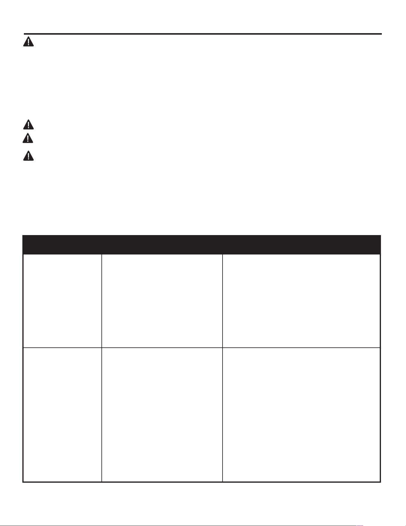
PILOT FLAME PATTERN
Figure 20 shows a correct pilot ame pattern. Figure 21 shows an incorrect pilot ame pattern. The
incorrect pilot ame is not touching the thermocouple. This will cause the thermocouple to cool. When
the thermocouple cools, the replace will shut down.
If pilot ame pattern is incorrect, as shown in Figure 21.
• turn replace off (see To Turn Off Gas to Appliance, page 24.
• see Troubleshooting, page 34.
WARNING: Do not allow fans to blow directly into the replace. Avoid any drafts that alter burner
ame patterns.
WARNING: Do not use a blower insert, heat exchanger insert or other acessory not approved for
use with this heater.
Fig. 20 - Correct Pilot Flame Pattern Fig. 21 - Incorrect Pilot Flame Pattern
31
CARE AND MAINTENANCE
WARNING: Turn off heater and let cool before servicing.
CAUTION: You must keep control areas, burner, and circulating air passageways of heater
clean. Inspect these areas of heater before each use. Have heater inspected yearly by a
qualied service person. Heater may need more frequent cleaning due to excessive lint
from carpeting, bedding material, pet hair, etc.
WARNING: Failure to keep the primary air opening(s) of the burner(s) clean may result in sooting
and property damage.
BURNER ORIFICE HOLDER AND PILOT AIR INLET HOLE
The primary air inlet holes allow the proper amount of air to mix with the gas. This provides a clean
burning ame. Keep these holes clear of dust, dirt, lint and pet hair. Clean these air inlet holes prior to
each heating season. Blocked air holes will create soot. We recommend that you clean the unit every
three months during operation and have replace inspected yearly by a qualied
service person.
We also recommend that you keep the burner tube and pilot assembly clean and free of dust and dirt.
To clean these parts we recommend using compressed air no greater than 30 PSI. Your local
computer store, hardware store or home center may carry compressed air in a can. If using
compressed air in a can, please follow the directions on the can. If you don’t follow directions on the
can, you could damage the pilot assembly.
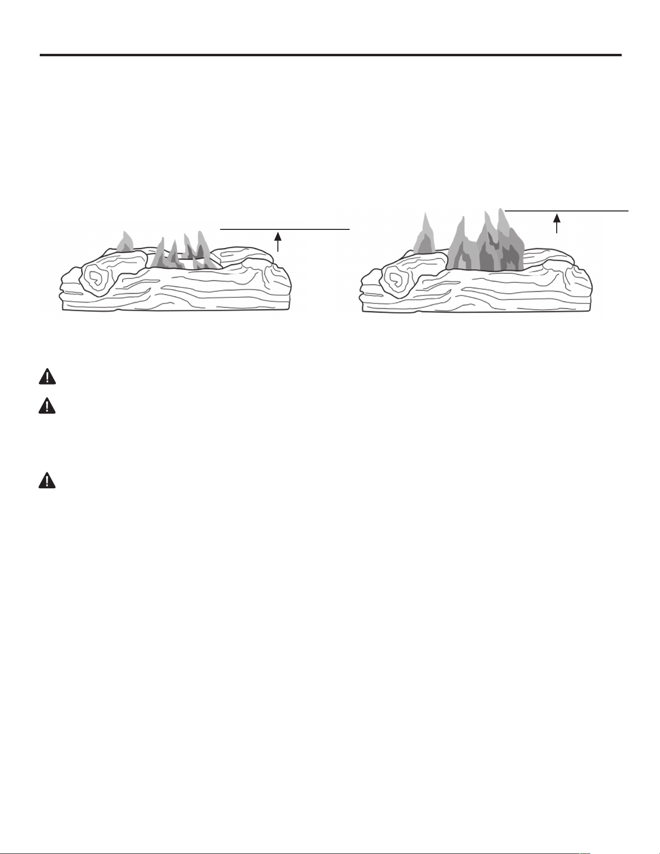
BURNER FLAME PATTERN
Figure 22 shows a correct burner ame pattern. Figure 23 shows an incorrect burner ame pattern.
The incorrect burner ame pattern shows sporadic, irregular ame tipping. The ame should not be
dark or have an orange/reddish tinge.
Note: When using the replace the rst time, the ame will be orange for approximately one hour until
the log cures.
If burner ame pattern is incorrect, as shown in Figure 23
• turn replace off (see To Turn Off Gas to Appliance, page 24).
• see Troubleshooting, page 34.
2-3 inches
above logs
6-12 inches
above logs
Fig. 22 - Correct Burner Flame Pattern Fig. 23 - Incorrect Burner Flame
Pattern
32
CARE AND MAINTENANCE
LOG SET
• If you remove the log set for cleaning, refer to pages 20 & 21, for placement instructions.
• Replace log set if broken or chipped (dime sized or larger).
CABINET
Air Passageways
Use a vacuum cleaner or pressurized air to clean.
Exterior
Use a soft cloth dampened with a mild soap and water mixture. Wipe the cabinet to remove dust.
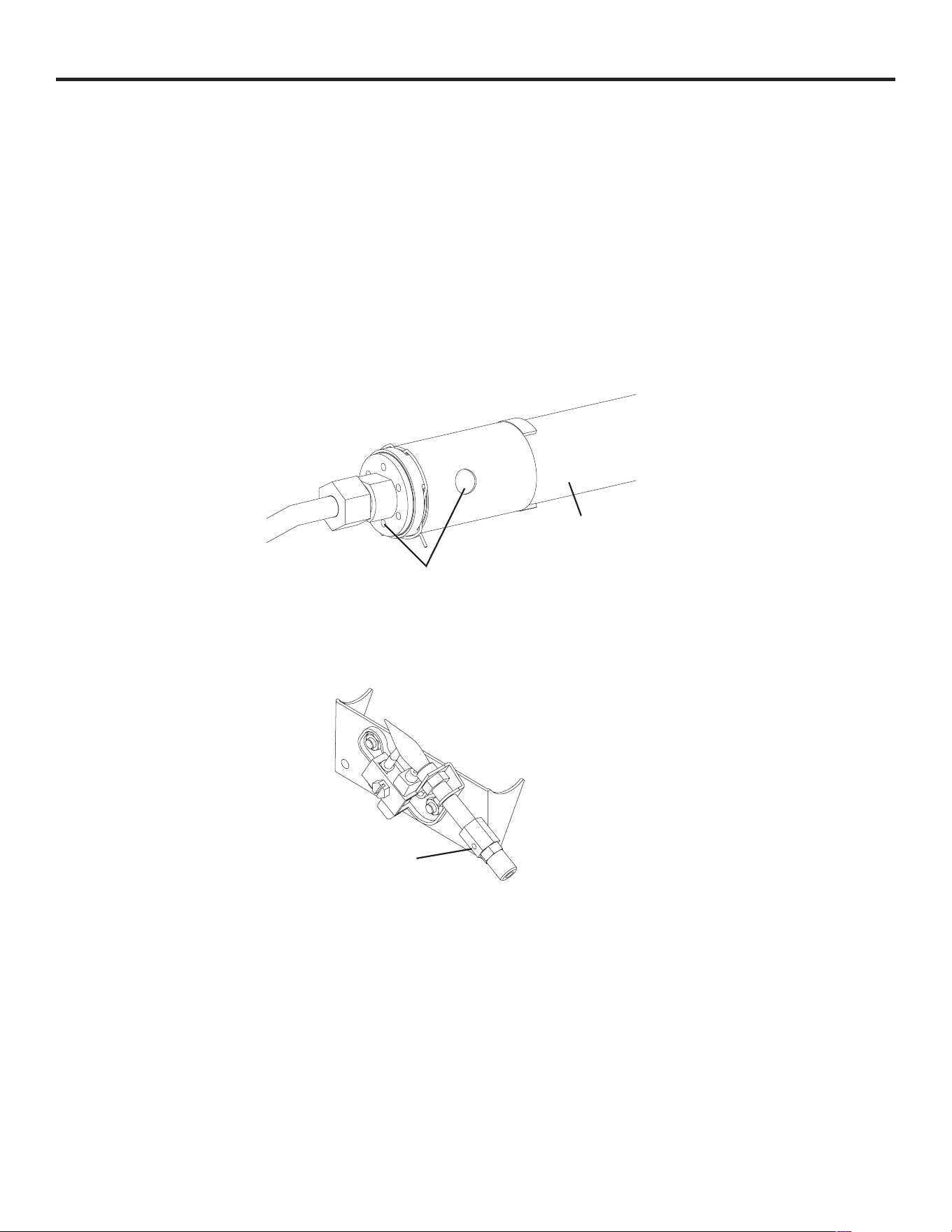
LP/NG Pilot Air Inlet Hole
Burner
Tube
Primary Air
Inlet Holes
Fig. 24 - Primary Air Inlet Slot on Burner Tube
1. Shut off unit including pilot. Allow unit to cool for at least 30 minutes.
2. Inspect burner, pilot and primary air inlet holes on orice holder for dust and dirt (See Fig. 24).
3. Blow air through the ports/slots and holes in the burner.
4. Check the orice holder located at the end of the burner tube again. Remove any large particles
of dust, dirt, lint or pet hair with a soft cloth or vacuum cleaner nozzle.
5. Blow air into the primary air holes on the orice holder.
6. In case any large clumps of dust have now been pushed into the burner repeat steps 3 and 4.
Clean the pilot assembly also. A yellow tip on the pilot ame indicates dust and dirt in the pilot
assembly. There is a small pilot air inlet hole about 2" from where the pilot ame comes out of the
pilot assembly (see Figures 34 or 35 depending on model). With the unit off, lightly blow air through
the air inlet hole. You may blow through a drinking straw if compressed air is not available.
Fig. 25 - Pilot Inlet Air Hole
33
TROUBLESHOOTING
WARNING: If you smell gas:
• Shut off gas supply.
• Do not try to light any appliance.
• Do not touch any electrical switch; do not use any phone in your building.
• Immediately call your gas supplier from a neighbor’s phone. Follow the gas supplier’s instructions.
• If you cannot reach your gas supplier, call the re department.
IMPORTANT: Operating heater where impurities in air exist may create odors. Cleaning supplies, paint, paint
remover, cigarette smoke, cements and glues, new carpet or textiles, etc., create fumes. These fumes may mix
with combustion air and create odors.
WARNING: Make sure that power is turned off before proceeding.
WARNING: Turn off and let cool before servicing. Only a qualied service person should service
and repair heater.
CAUTION: Never use a wire, needle, or similar object to clean ODS/pilot. This can damage ODS/ pilot unit.
PROBLEM POSSIBLE CAUSE CORRECTIVE ACTION
When ignitor button
is pressed in, there
is no spark at ODS/
pilot.
1. Ignitor electrode is
positioned wrong.
2. Ignitor electrode is broken.
3. Ignitor electrode is not
connected to ignitor cable.
4. Ignitor cable is pinched or
wet.
5. Damaged ignitor cable.
6. Bad piezo ignitor.
1. Replace electrode.
2. Replace electrode.
3. Replace ignitor cable
4. Free ignitor cable if pinched by any
metal or tubing. Keep ignitor cable dry.
5. Replace ignitor cable.
6. Replace piezo ignitor.
When ignitor button
is pressed in, there
is a spark at ODS/
pilot but no ignition.
1. Gas supply is turned off or
equipment shutoff valve is
closed.
2. Control knob not fully
pressed in while pressing
ignitor button.
3. Air in gas lines when
installed.
4. ODS / pilot is clogged.
5. Control knob not in PILOT
position.
6. Depleted gas supply (propane).
1. Turn on gas supply or open equipment
shutoff valve.
2. Fully press in control knob while
pressing ignitor button.
3. Continue holding down control knob.
Repeat igniting operation until air is
removed.
4. Clean ODS/pilot (see Care and
Maintenance, page 32) or replace
ODS/pilot assembly.
5. Turn control knob to PILOT position.
6. Contact local propane/LP gas company.
SERVICE HINTS
When Gas Pressure Is Too Low
• pilot will not stay lit
• burners will have delayed ignition
• replace will not produce specied heat
• for propane/LP units, propane/LP gas supply may be low
You may feel your gas pressure is too low. If so, contact your local natural or propane/LP gas supplier.

34
TROUBLESHOOTING
PROBLEM POSSIBLE CAUSE CORRECTIVE ACTION
ODS/pilot lights
but ame goes out
when control knob is
released.
1. Control knob is not fully
pressed in.
2. Control knob is not pressed
in long enough.
3. Equipment shutoff valve is
not fully open.
4. Thermocouple connection is
loose.
5. Thermocouple damaged.
6. Control valve damaged.
1. Press in control knob fully.
2. After ODS/pilot lights, keep control
knob pressed in 30 seconds.
3. Fully open equipment shutoff valve.
4. Hand tighten until snug, and then
tighten ¼ turn more.
5. Replace thermocouple.
6. Contact customer service.
Burner(s) does not
light afterODS/pilot
is lit.
1. Burner orice is clogged.
2. Burner orice diameter is
too small.
3. Inlet gas pressure is too low.
1. Clean burner orice (see Care and
Maintenance, page 32) or contact
customer service.
2. Contact customer service.
3. Contact your gas supplier.
Delayed ignition of
burner(s).
1. Manifold pressure is too low.
2. Burner orice is clogged.
1. Contact your gas supplier.
2. Clean burner (see Care and Mainte-
nance, page 32) or contact customer
service.
Burner backring
during combustion.
1. Burner orice is clogged or
damaged.
2. Burner is damaged.
3. Gas regulator is damaged.
1. Clean burner orice (see Care and
Maintenance, page 32 or contact
customer service.
2. Contact dealer or customer service.
3. Replace gas regulator.
High yellow ame
during burner
combustion
1. Not enough air.
2. Gas regulator is defective.
3. Inlet gas pressure is too low.
1. Check burner for dirt and debris. If found, clean
burner (see Care and Maintenance, page 32).
2. Replace gas regulator.
3. Contact your gas supplier.
Gas odor during
combustion.
1. Foreign matter between
control valve and burner.
2. Gas leak. (See Warning
Statement at top of page 34).
1. Take apart gas tubing and remove foreign
matter.
2. Locate and correct all leaks (see “Check-
ing Gas Connections,” page 22).
Heater produces a
clicking/ticking noise
just after burner is lit
or shut off.
1. Metal is expanding while
heating or contracting
while cooling.
1. This is common with most heaters. If
noise is excessive, contact qualied
service technician.

35
TROUBLESHOOTING
PROBLEM POSSIBLE CAUSE CORRECTIVE ACTION
White powder resi-
due forming within
burner box or on
adjacent walls or
furniture.
1. When heated, the vapors
from furniture polish, wax,
carpet cleaners, etc., turn
into white powder residue.
1. Turn heater off when using furniture
polish, wax, carpet cleaner or similar
products.
Heater produces
unwanted odors.
1. Heater is burning vapors
from paint, hair spray, glues,
etc. See IMPORTANT state-
ment, page 34.
2. Gas leak. See Warning
Statement, page 34.
3. Low fuel supply.
1. Ventilate room. Stop using odor
causing products while heater is
running.
2. Locate and correct all leaks (see
“Checking Gas Connections,” page 22).
3. Rell supply tank (Propane /LP models).
Heater shuts off
in use (ODS oper-
ates).
1. Not enough fresh air is
available.
2. Low line pressure.
3. ODS/pilot is partially
clogged.
1. Open window and/or door for
ventilation.
2. Contact local gas supplier.
3. Clean ODS/pilot (see Care and
Maintenance, page 32).
Gas odor exists
even when control
knob is in OFF posi-
tion.
1. Gas leak. See Warning
Statement at top of page 34.
2. Control valve is
defective.
1. Locate and correct all leaks (see
“Checking Gas Connections”, page 22).
2. Contact customer service.
Moisture/conden-
sation noticed on
windows.
1. Not enough combustion/
ventilation air.
1. Refer to “Air for Combustion and
Ventilation” requirements, page 9-11.
Slight smoke or
odor during initial
operation
Heater produces
a whistling noise
when burner is lit.
1. Residues from
manufacturing process.
1. Problem will stop after a few hours of
operation.
1. Turning control knob to high (5)
position when burner is cold.
2. Air in gas line.
3. Air passageways on
heater are blocked.
4. Dirty or partially clogged
burner orice.
1. Turn control knob to low (1) position and
let warm up for a minute.
2. Operate burner until air is removed from
line. Have gas line checked by local
propane/LP gas company.
3. Observe minimum installation
clearances (Fig. 6, page 12)
4. Clean burner (see Care and Maintenance,
page 32) or contact customer service.
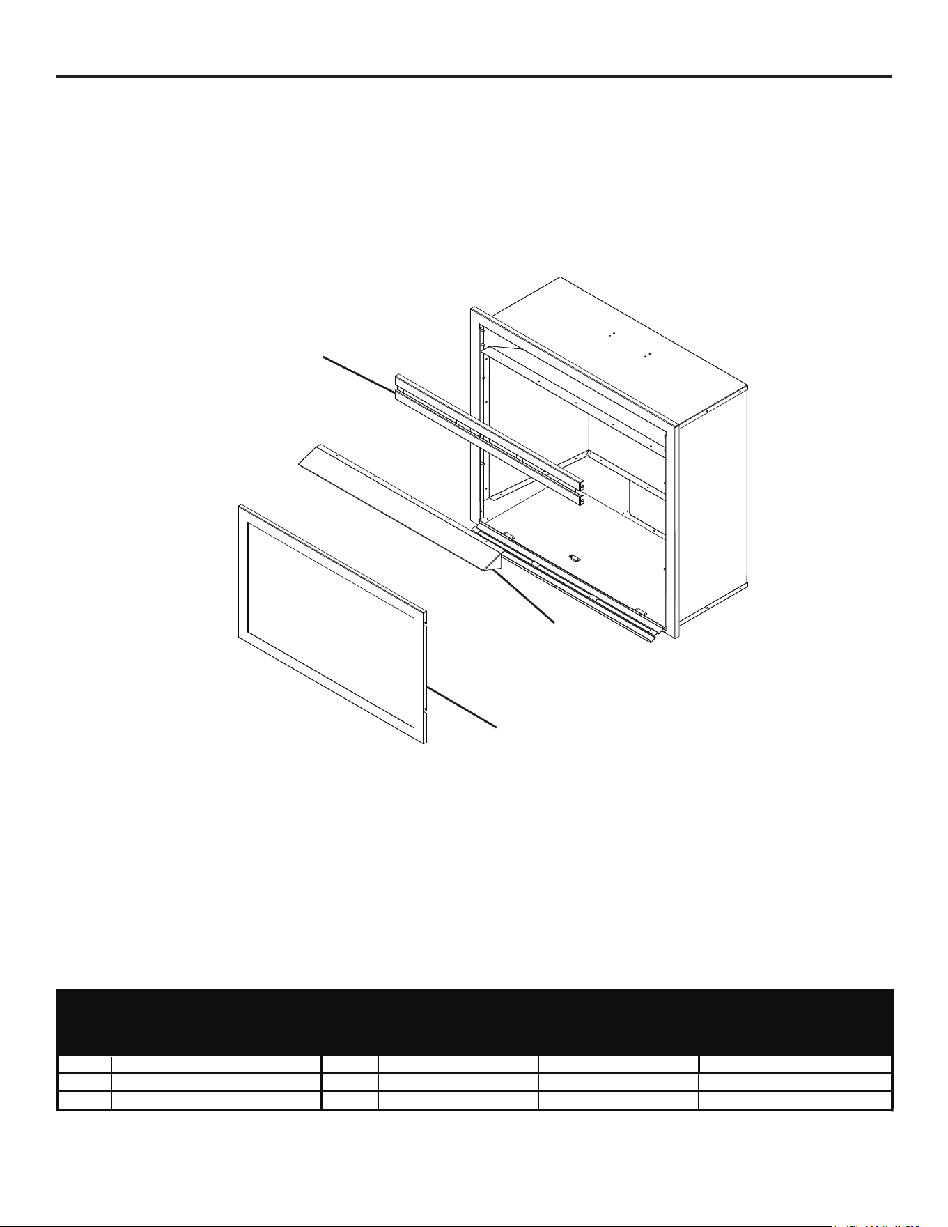
36
REPLACEMENT PARTS
For replacement parts, call our customer service department at 1-877-447-4768, 8:30 a.m. – 4:30 p.m.,
CST, Monday – Friday.
FIREBOX MODELS VFF-PH(20NGB)(20NG)(20NG-C1)(20NG-2T1),
VFF-PH(20LPB)(20LP)(20LP-C2)(20LP-2T2), VFF-PH(26NG)(26NG-T1)(26NG-2H1)
VFF-PH(26LP)(26LP-T2)(26LP-2H2), VFF-PH(32NGB)(32NG)(32NG-H1)(32NG-2C1),
VFF-PH(32LPB)(32LP)(32LP-H2)(32LP-2C2)
1
2
3
VFF-PH20NG/LP Series
1 Top Grille 1 700-S1014B 700-M1014B
2 Hood 1 700-S1012B 700-M1012B
3 Window Frame Assembly 1 700-AS1015 700-AM1015
ITEM
No.
DESCRIPTION QTY
PART NUMBER
700-L1014B
700-L1012B
700-AL1015
VFF-PH32NG/LP SeriesVFF-PH26NG/LP Series
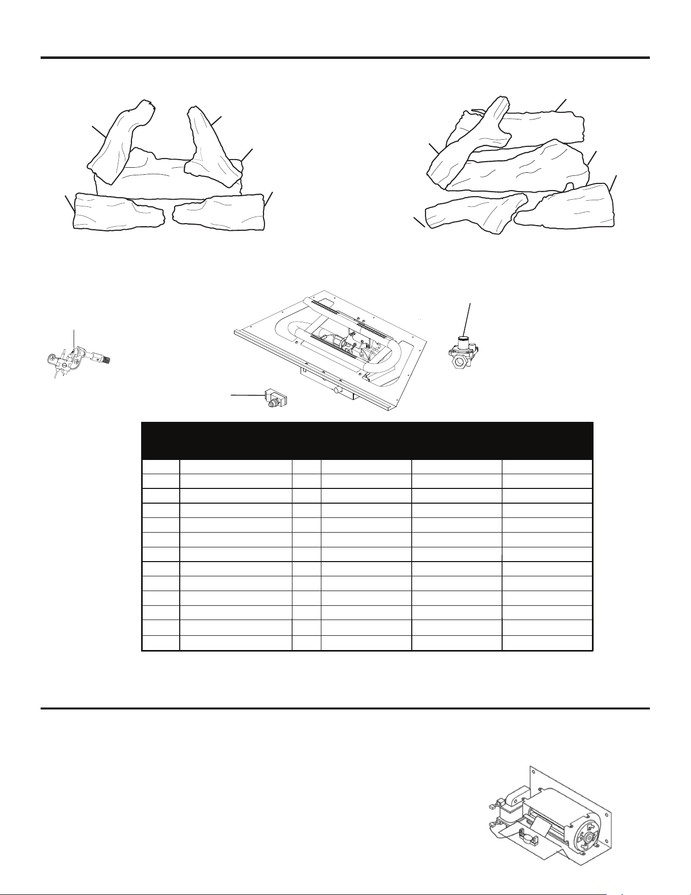
37
VFF-PH(32NGB)(32NG)(32NG-H1)(32NG-2C1)
VFF-PH(32LPB)(32LP)(32LP-H2)(32LP-2C2)
REPLACEMENT PARTS LIST
For replacement parts, call our customer service department at 1-877-447-4768, 8:30 a.m. – 4:30 p.m.,
CST, Monday – Friday.
2
ACCESSORIES
NOTICE: All accessories may not be available for all replace models.
THERMOSTAT-CONTROLLED BLOWER KIT - GFB100 For all models. Provides better heat
distribution. Makes replace
more efcient. Automatically turns off and on as needed.
VFF-PH20NG/LP Series VFF-PH26NG/LP Series VFF-PH32NG/LP Series
1 Log Set (complete) 1 700-S1018 700-M1018 700-L1018
1 - 1 Log 1 1 700-S1018-01 700-M1018-01 700-L1018-01
1 - 2
Log 2 1 700-S1018-02 700-M1018-02 700-L1018-02
1 - 3 Log 3 1 700-S1018-03 700-M1018-03 700-L1018-03
1 - 4 Log 4 1 700-S1018-04 700-M1018-04 700-L1018-04
1 - 5 Log 5 1 700-S1018-05 700-M1018-05 700-L1018-05
2 - 1
ODS Pilot - LP 1
Be3288e Be3288e Be3288e
2 - 2
ODS Pilot - NG 1 Be3289e Be3289e Be3289e
Regulator - LP
1
Regulator - NG
1
4
Ignitor Module 1 301-01015-06 301-01015-06 301-01015-06
ITEM
No.
DESCRIPTION
PART NUMBER
QTY
5
6
Remote Receiver
Thermostat Remote
1
1
-
-
-
-
80-05-102*
80-05-101*
GR-130A
GR-130
GR-130A
GR-130
GR-130A
GR-130
3 - 1
3 - 2
VFF-PH(20NGB)(20NG)(20NG-C1)(20NG-2T1)
VFF-PH(20LPB)(20LP)(20LP-C2)(20LP-2T2)
VFF-PH(26NG)(26NG-T1)(26NG-2H1)
VFF-PH(26LP)(26LP-T2)(26LP-2H2)
1-1
1-2
1-3
1-5
1-4
1-1
1-2
1-3
1-5
1-4
7
1
6
9
10
8
4
3
5
14
2
3
4
* Item/version not shown in exploded parts diagram

38
39
33
This limited warranty is extended to the original retail purchaser of this heater and warrants against any
2
2
two
two
years
years
40
34
GHP Group, Inc.
6440 W Howard St
Niles, IL 60714-3302
Tel: (877) 447-4768
www.ghpgroupinc.com
GHP Group, Inc.
6440 W Howard St
Niles, IL 60714-3302
