VERSION A0
March 13, 2024
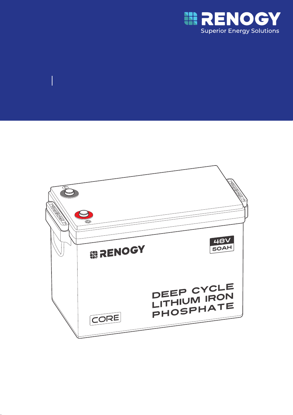
Deep Cycle Lithium Iron Phosphate Battery
RENOGY
Core LT (Low Temperature) Series
RBT4850LFPSH
USER MANUAL
48V 50Ah
Before Getting Started
The user manual provides important operation and maintenance instructions for Renogy Core
LT (Low Temperature) Series 48V 50Ah Deep Cycle Lithium Iron Phosphate Battery (hereinafter
referred to as battery).
Read the user manual carefully before operation and save it for future reference. Failure to
observe the instructions or precautions in the user manual can result in electrical shock, serious
injury, or death, or can damage the battery, potentially rendering it inoperable.
z
Renogy ensures the accuracy, sufficiency, and the applicability of information in the user
manual at the time of printing due to continual product improvements that may occur.
z
Renogy assumes no responsibility or liability for personal and property losses, whether
directly and indirectly, caused by the user’s failure to install and use the product in
compliance with the user manual.
z
Renogy is not responsible or liable for any failure, damage, or injury resulting from repair
attempts by unqualified personnel, improper installation, or inappropriate operation.
z
The illustrations in the user manual are for demonstration purposes only. Details may appear
slightly different depending on product revision and market region.
z
Renogy reserves the right to change the information in the user manual without notice. For
the latest user manual, visit renogy.com.
Disclaimer
Renogy Core LT (Low Temperature) Series 48V 50Ah Deep Cycle Lithium Iron Phosphate Battery
User Manual © 2024 Renogy. All rights reserved.
RENOGY
and
are registered trademarks of Renogy.
z
All information in the user manual is subject to copyright and other intellectual property
rights of Renogy and its licensors. The user manual may not be modified, reproduced, or
copied, in whole or in part, without the prior written permissions of Renogy and its licensors.
z
The registered trademarks in the user manual are the property of Renogy. The unauthorized
use of the trademarks is strictly prohibited.
Online Manual
User Manual

Symbols Used .................................................................................................................................... 1
Introduction ...................................................................................................................................... 1
Key Features ...................................................................................................................................... 1
SKU ..................................................................................................................................................... 1
What’s In the Box?.............................................................................................................................2
Required Tools & Accessories .........................................................................................................2
Get to Know Deep Cycle Lithium Iron Phosphate Battery ...........................................................3
Dimensions ........................................................................................................................................3
How to Size Battery Adapter Cables?.............................................................................................4
Fix the Battery to a Position (Optional) .........................................................................................4
Step 1. Plan a Mounting Site ............................................................................................................5
Step 2. Wear Insulating Gloves ........................................................................................................ 5
Step 3. Remove the Dust Cover ....................................................................................................... 6
Step 4. Check the Battery ...............................................................................................................6
Step 5. Run the Battery Adapter Cables Through the Insulating Sleeves ................................. 6
Step 6. Install Battery Terminals .................................................................................................... 7
Step 7. Install the Insulating Sleeves ............................................................................................. 7
Step 8. Connect the Battery to Other Devices ..............................................................................8
How to Connect Renogy Core Batteries in Parallel.......................................................................8
Calculate Voltage and Current in Parallel Connections .......................................................................8
Balance Batteries Prior to Connection .................................................................................................... 9
Parallel Connection — Installation Steps ............................................................................................... 10
Battery Cell Balancing ............................................................................................................................... 10
Charging/Discharging Parameter Settings ................................................................................ 10
Battery Charging and Discharging Logic......................................................................................11
Charging Logic .............................................................................................................................................11
Discharging Logic .......................................................................................................................................12
How to Estimate the Battery SOC? ............................................................................................... 12
Self-heating Function .................................................................................................................... 12
Battery Management System ....................................................................................................... 12
Troubleshooting.............................................................................................................................. 13
Specifications ................................................................................................................................. 14
General ......................................................................................................................................................... 14
Operation Parameters ............................................................................................................................... 15
Table of Contents

Maintenance & Storage .................................................................................................................. 15
Inspection .................................................................................................................................................... 15
Cleaning ....................................................................................................................................................... 15
Checking Voltage ....................................................................................................................................... 15
Storage ......................................................................................................................................................... 16
Important Safety Instructions ..................................................................................................... 16
General ......................................................................................................................................................... 16
Battery Safety ............................................................................................................................................. 16
Renogy Support .............................................................................................................................. 17

— 1 —
Symbols Used
The following symbols are used throughout the user manual to highlight important information.
WARNING: Indicates a potentially dangerous condition which could result in injury or
death.
CAUTION: Indicates a critical procedure for safe and proper installation and operation.
NOTE: Indicates an important step or tip for optimal performance.
Introduction
The Renogy Core LT (Low Temperature) Series 48V 50Ah Deep Cycle Lithium Iron Phosphate
Battery is designed for the drop-in replacement of deep-cycle lead-acid batteries with its smaller
size.
Weighing only half of the lead-acid counterparts, the battery can be safely discharged to 100%
Depth of Discharge (DOD), delivering twice the energy. Manufactured with automotive grade
battery cells, the battery features the highest safety standards and an extended 6000+ cycle life.
In addition, the Smart Battery Management System (BMS) provides comprehensive protection to
the battery.
Key Features
z
Unparalleled Performance
Features a greater energy density, a deeper discharge capability, a higher round-trip
efficiency, and a faster charging speed in a smallest size over counterparts in the market.
z
Uncompromising Quality
Ensures an exceptional lifespan with more than 6000 cycles (80% DOD), a continuous charge
current of 50A and a continuous discharge current of 50A, and a wide range of operating
temperatures with the automotive grade battery cells.
z
Reliable Protection Mechanisms
Designed with a sturdy internal structure for RV use, and includes multiple levels of protection
such as low temperature cut-off and precise balancing through the battery management
system.
z
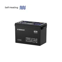
Intelligent Self-heating Function & More Stable Performance
The built-in heater operates automatically at at low temperatures to keep the battery
charging, assuring charging performance at low temperature and increasing battery lifespan.
z
Easy to Expand
It supports up to 16 batteries in parallel, delivering a maximum of 48V 800Ah at 38.4kWh.
SKU
Renogy Core LT (Low Temperature) Series
48V 50Ah Deep Cycle Lithium Iron Phosphate Battery
RBT4850LFPSH
— 2 —
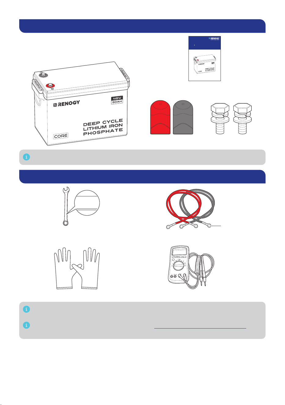
What’s In the Box?
VERSION A0
March 13, 2024
Deep Cycle Lithium Iron Phosphate Battery
RENOGY
Core LT (Low Temperature) Series
RBT4850LFPSH
USER MANUAL
48V 50Ah
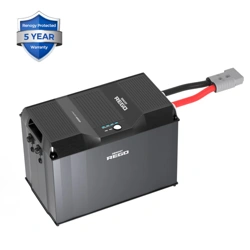
Renogy Core LT (Low Temperature) Series
48V 50Ah Deep Cycle
Lithium Iron Phosphate Battery × 1
User Manual × 1
Long Terminal Bolt × 2
Insulating Sleeve × 2
M8*1.25*20 mm
Make sure that all accessories are complete and free of any signs of damage.
Required Tools & Accessories
MultimeterInsulating Gloves
Wrench (9/16 inches)
Battery Adapter Cables × 2
M8
14mm
14mm
14mm
Prior to installing and configuring the battery, prepare the recommended tools,
components, and accessories.
For how to size battery adapter cables, refer to “How to Size Battery Adapter Cables?” in
this manual.
— 3 —
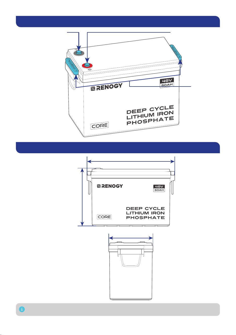
Get to Know Deep Cycle Lithium Iron Phosphate Battery
Positive Terminal (M8)Negative Terminal (M8)
Lift Handles
Dimensions
15.1 in (384 mm)
7.6 in (195 mm)
9.8 in
(248 mm)
Dimension tolerance: ±0.2 in (0.5 mm)
— 4 —
How to Size Battery Adapter Cables?
Use appropriately sized Battery Adapter Cables (sold separately) based on expected load. Refer to
the table below for copper cable ampacities with different gauge sizes.
Cable Gauge Size Ampacity Cable Gauge Size Ampacity
14 AWG (2.08 mm²) 35A 2 AWG (33.6 mm²) 190A
12 AWG (3.31 mm²) 40A 1 AWG (42.4 mm²) 220A
10 AWG (5.25 mm²) 55A 1/0 AWG (53.5 mm²) 260A
8 AWG (8.36 mm²) 80A 2/0 AWG (67.4 mm²) 300A
6 AWG (13.3 mm²) 105A 4/0 AWG (107 mm²) 405A
4 AWG (21.1 mm²) 140A
The above values are from the NEC Table 310.17 for copper cables rated at 194°F (90°C),
operating at an ambient temperature of no more than 86°F (30°C). Cables longer than
13 feet (4000 mm) may require thicker gauge wires to prevent excessive voltage drop in
undersized wiring.
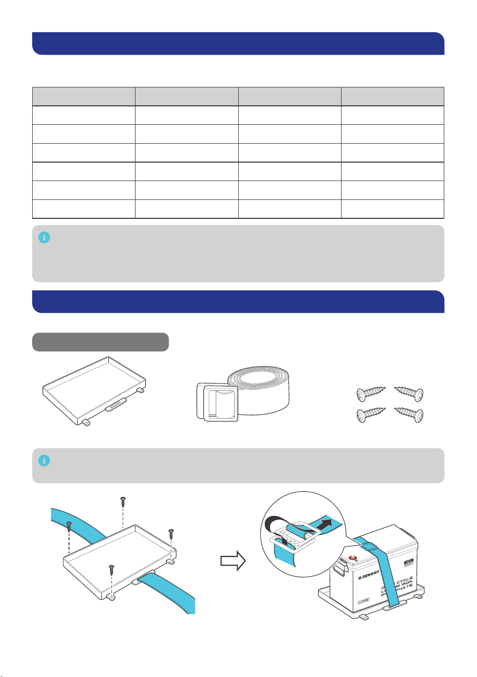
Fix the Battery to a Position (Optional)
Securing the battery prevents damage to the battery from loose cables and bumps.
Recommended Components
Battery Tray Tie Down Strap Mounting Screws × 4
Alternative mounting methods are allowed to meet the requirements of specific
applications.
— 5 —
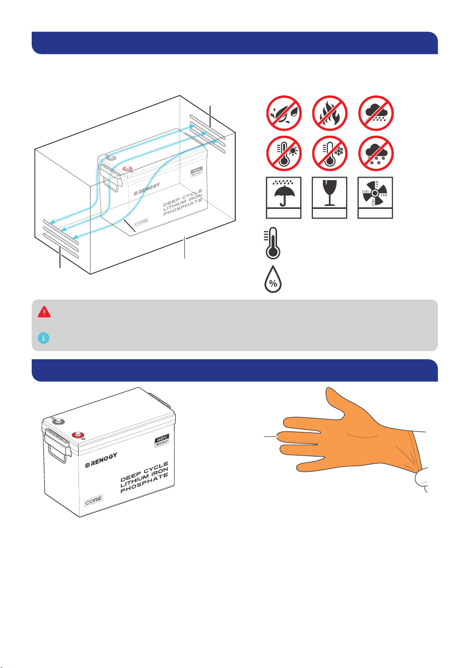
Step 1. Plan a Mounting Site
For optimal battery performance, it is recommended to install the battery in a clean, cool, and dry
location, free from any accumulation of water, oil, or dirt. Accumulation of such materials on the
battery can lead to current leakage, self-discharge, and even short-circuiting.
KEEP DRY FRAGILE VENTILATION
Charge: -4°F–131°F / -20°C–55°C
Discharge: -4°F–140°F / -20°C–60°C
10%–95%
Vent
Vent
Enclosed space
Air
cross-flow
Sufficient air flow must be provided to prevent excessive heat build-up and to minimize
temperature variation between the connected batteries.
This user manual takes a battery as an example to illustrate how to install the battery.
Step 2. Wear Insulating Gloves
Insulating Gloves
— 6 —
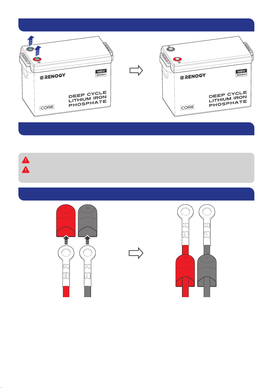
Step 3. Remove the Dust Cover
Step 4. Check the Battery
Inspect the battery for any visible damage including cracks, dents, deformation, and other visible
abnormalities. All connector contacts shall be clean, free of dirt and corrosion, and dry.
Do not touch the exposed electrolyte or powder if the battery is damaged.
If uncovered electrolyte or powder contacts your skin or eyes, flush it out immediately with
plenty of clean water and seek medical attention.
Step 5. Run the Battery Adapter Cables Through the Insulating Sleeves
— 7 —
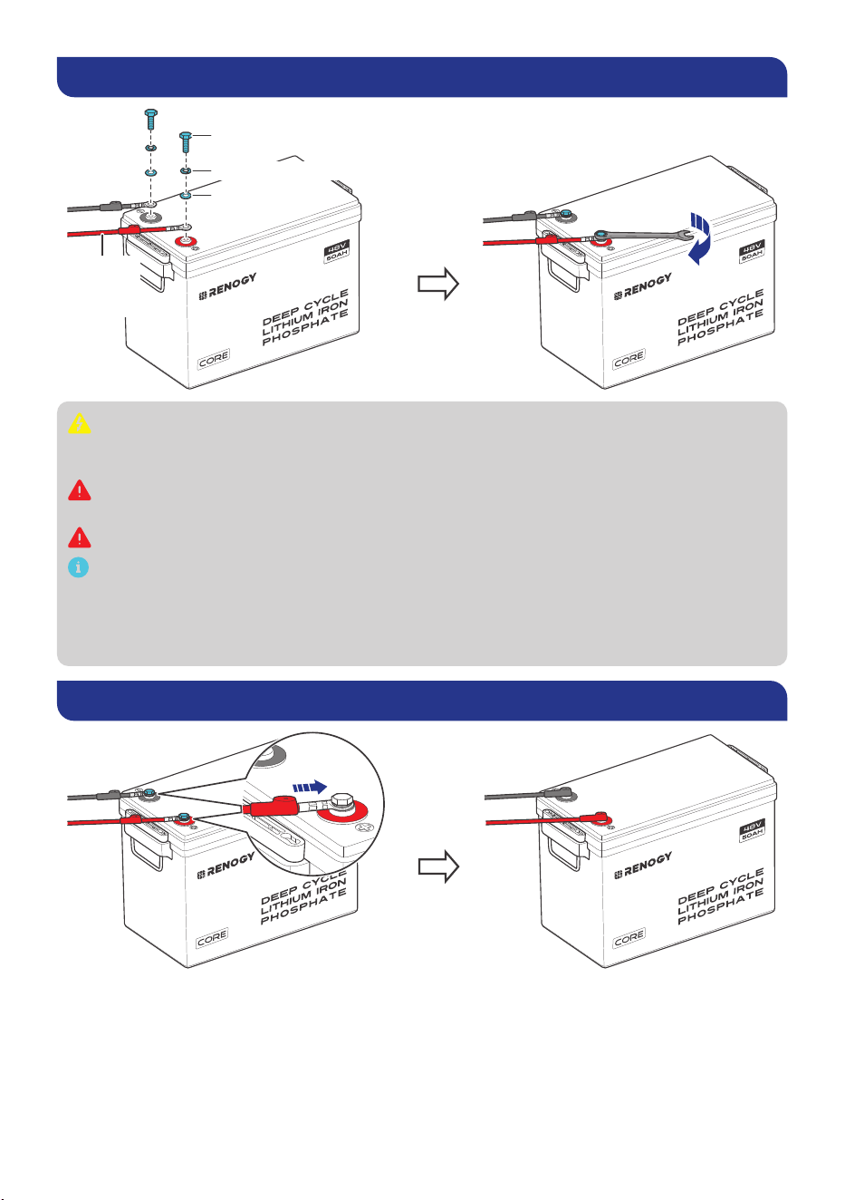
Step 6. Install Battery Terminals
10 N·m
Battery
Adapter
Cable
Spring Washer
Long Terminal Bolts
Flat Washer
Ensure the cable lug and the top surface of the terminal are in contact, and place the
washers on top of the lug. Do not place the washers between the battery terminal and the
cable lug to avoid high resistance and excessive heating.
Avoid short-circuiting the battery terminals to prevent irreversible damage to the system
and battery caused by current bursts.
Verify polarity before wiring to avoid irreversible battery damage due to polarity reversal.
To ensure safe and reliable operation of the system, please follow the manufacturer’s
recommended torque specifications when securing cable connections. Over-tightening
can result in terminal breakage, while loose connections can lead to terminal meltdown or
fire. When securing multiple cable lugs on a single battery terminal, use the included Long
Terminal Bolts.
Step 7. Install the Insulating Sleeves
— 8 —
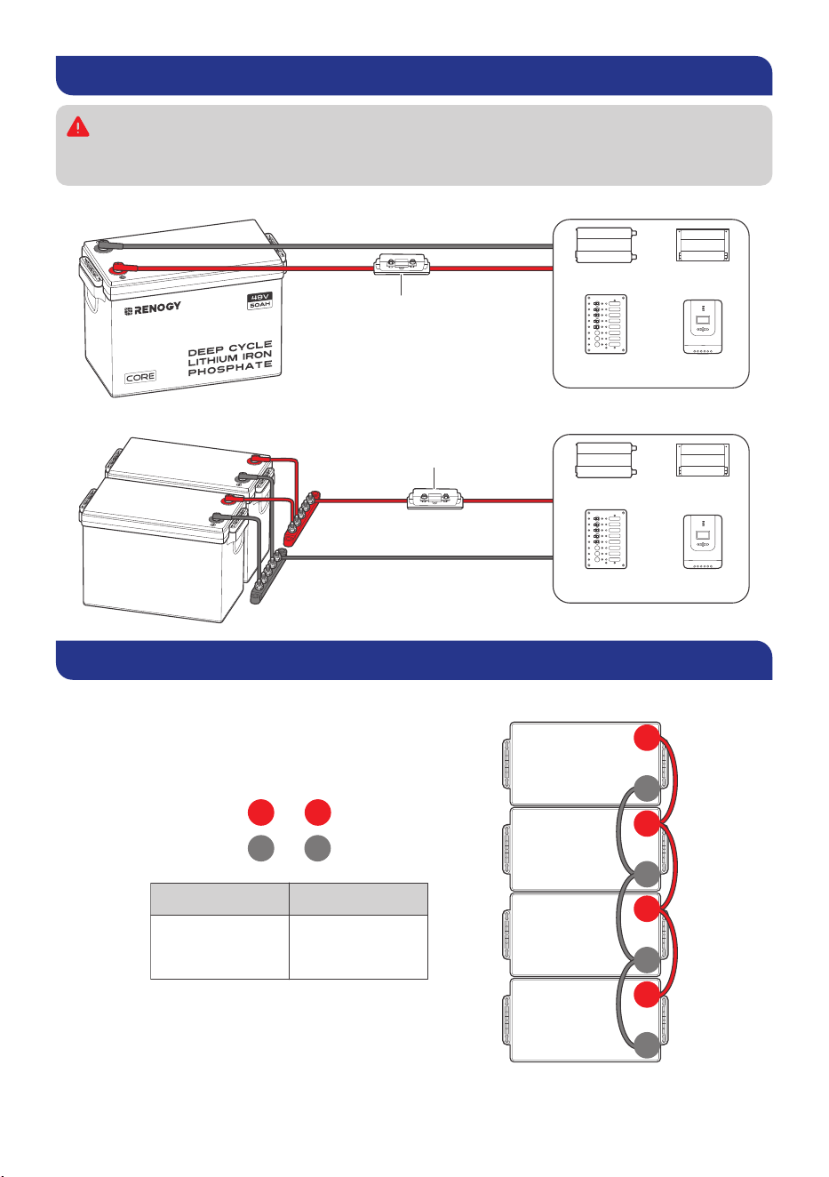
Step 8. Connect the Battery to Other Devices
Please use circuit breakers, fuses, or disconnects appropriately sized by a certified
electrician, licensed installers, or regional code authorities to protect all electrical
equipment.
█
For a Single Battery
Battery Fuse
Inverter DC-DC
Converter
DC Distribution
Panel
Charge
Controller
█
For Batteries in Parallel
Battery Fuse
Inverter DC-DC
Converter
DC Distribution
Panel
Charge
Controller
How to Connect Renogy Core Batteries in Parallel
Calculate Voltage and Current in Parallel Connections
to
to
+ +
- -
48V 200Ah
Parallel Connection
System Voltage
48V
System current
Sum of the
individual
battery currents
48V
50Ah
48V
50Ah
48V
50Ah
48V
50Ah
+
-
+
-
+
-
+
-
— 9 —
Do not connect batteries with different chemistries, rated capacities, nominal voltages,
brands, or models in parallel or in series. This can result in potential damage to the batteries
and the connected devices, and can also pose safety risks.
Avoid connecting batteries that have been purchased for more than half a year. Over time,
batteries can degrade and their performance may decrease, which can affect their ability
to deliver reliable power and may lead to safety hazards.
The cables between each connected battery should be of equal length to ensure that all
batteries can work equally together.
You can connect up to 16 batteries in parallel.
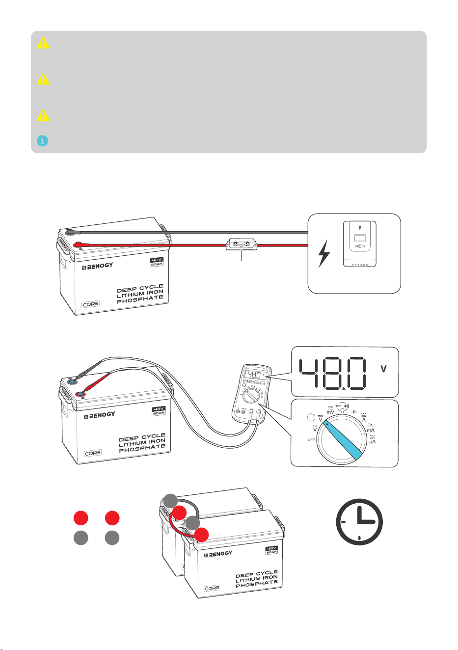
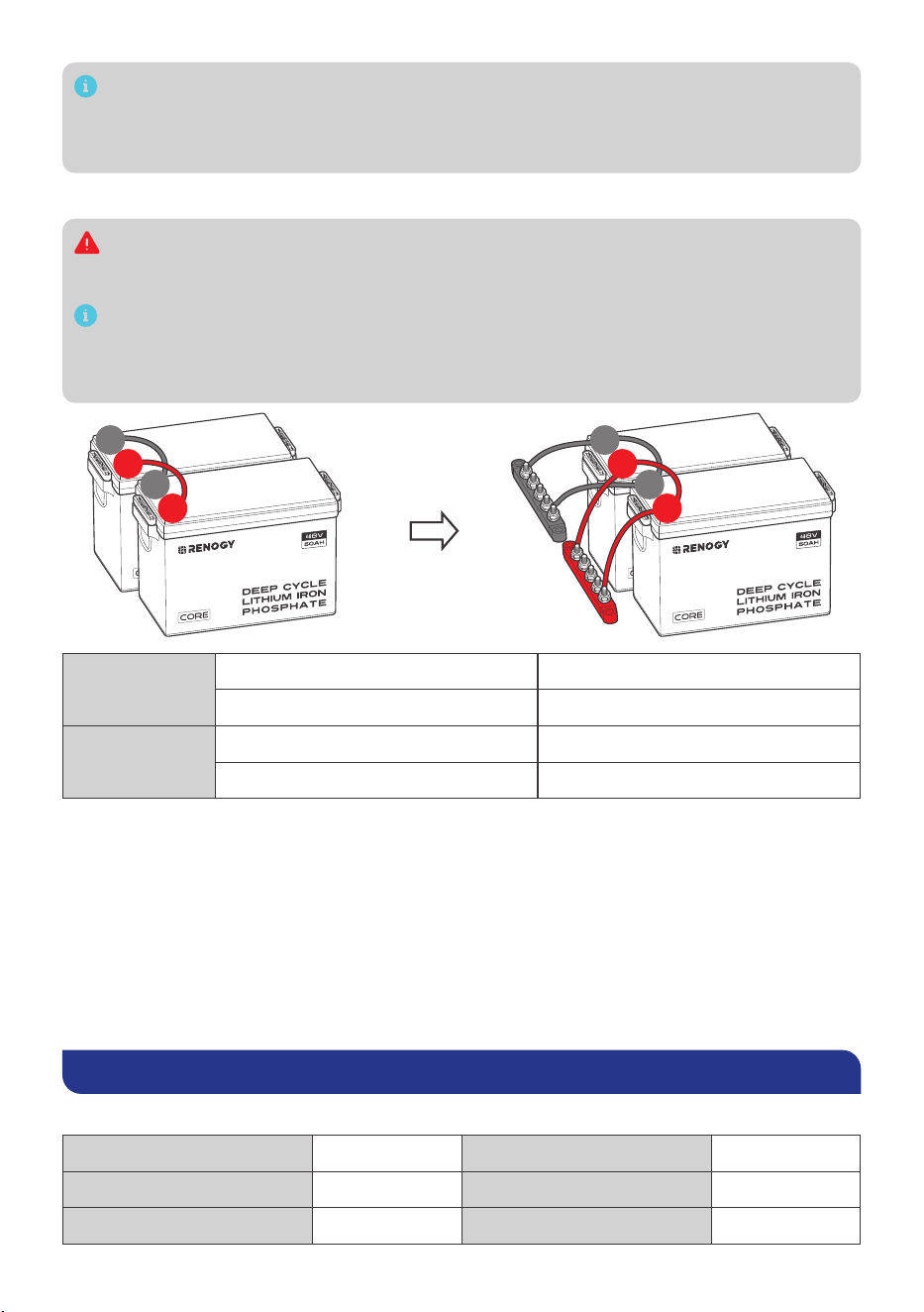
Balance Batteries Prior to Connection
Before connecting batteries in parallel, it is important to balance them to reduce voltage
differences and optimize their performance. Follow these three steps:
Step 1: Charge each battery individually to its full capacity using a suitable charger.
Battery Fuse
Charge
Controller
Step 2: Use a voltmeter to measure the voltage of each battery. It is best to keep the voltage
difference of each battery less than 0.2V.
Step 3: Connect all the batteries in parallel and allow them to rest together for 12 to 24 hours.
12~24h
to
to
+ +
- -
+
+
-
-
— 10 —
It is recommended to periodically rebalance the battery voltages every six months when
connecting multiple batteries as a battery system. Slight voltage differences can occur
among batteries over time due to factors like battery chemistry, capacity, temperature, and
usage patterns.
Parallel Connection — Installation Steps
You can choose suitable busbars in parallel connections. Busbars help handle high currents
and are typically arranged in a parallel or stacked configuration to distribute electrical
power efficiently.
Note that the cable connection methods provided below are for reference purposes only,
as the optimal approach may vary depending on the specific situation. It is essential to
consider various factors, such as the cable size, equipment used, and environmental
conditions.
+
+
-
-
+
+
-
-
2P
Battery System 48V 100Ah
Energy 4800Wh
16P
Battery System 48V 800Ah
Energy 38400Wh
Battery Cell Balancing
The battery employs bypass circuit to maintain the balance between each battery cell group.
Each battery cell group is connected with a bypass resistor and a switch in parallel. During the
charging process, if the highest-voltage battery cell group reaches the set balancing starting
voltage and the voltage difference between the highest-voltage and the lowest-voltage battery
cell group exceeds the set voltage difference, the switch connected to the highest-voltage
battery cell group will be closed to shunt the charge current around the highest-voltage battery
cell group through the bypass resistor until the voltage difference drops below the set value. To
avoid excessive energy loss, the battery cell balancing is only performed during the charging
process.
Charging/Discharging Parameter Settings
█
Charge
Charge/Boost Voltage 54.0V Boost Return Voltage 49.5V
Bulk/Absorption Voltage 54.0V Overvoltage Disconnect 56.3V
Bulk/Absorption Voltage 54.0V / Disabled Overvoltage Reconnect 53.3V
— 11 —
█
Discharge
Low Voltage Reconnect 47.3V Undervoltage Warning 45.0V
Undervoltage Shutdown 42.0V
The parameters in the table are applicable to 48V (15 cells) battery packs.
Battery Charging and Discharging Logic
The battery may be received at a partial state of charge (SOC) depending on the time between
manufacturing and shipping. It is crucial to fully charge the battery before its initial use. In case
the battery shuts off due to low SOC, promptly disconnect it from loads and charge it to prevent
irreversible damage. Follow the instructions in this user manual for proper charging and usage to
ensure optimal battery performance and longevity.
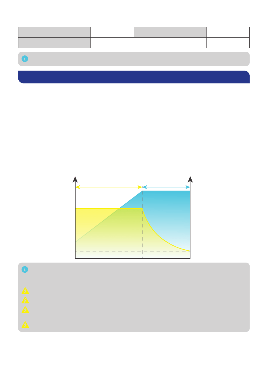
Charging Logic
The standard charging process for the battery involves charging at a constant current of 50A until
the battery voltage reaches 54V, followed by charging at a constant voltage of 54V while tapering
the charge current. The charging process is considered complete when the charge current is less
than 2.5A (also known as tail current).
The standard charging process typically takes 1.5 hours and requires battery temperatures to
be between 32°F and 131°F (0°C and 55°C) for safe charging. Leaving the battery on float will
continue to balance the battery cells without damaging the battery.
Constant Current Constant Voltage
U/VI/A
Current
Voltage
50A
54V
2.5A
Lithium batteries are compatible with various charging methods, including MPPT charge
controller, AC charger, and DC-DC charger. The crucial parameter setting for these chargers
is to set the charge voltage, boost voltage, or bulk voltage at 54V (±0.2V).
Do not overcharge or overdischarge the battery.
Do not discharge the battery at high temperatures above 140°F (60°C).
Only charge the battery with a battery charger or charge controller that is compatible with
lithium iron phosphate batteries.
Do not exceed the maximum continuous charge current (50A) of the battery.
— 12 —
Discharging Logic
During standard discharging, the battery is discharged at a constant current of 50A until the
voltage drops to 42V. To ensure safe discharging, the battery temperature should be between
-4°F (-20°C) and 131°F (60°C).
To ensure safe and optimal battery usage, it is recommended to pair the battery with
discharge equipment that features a low voltage disconnect (LVD) function.
Do not connect large loads to the battery when it is running low.
Do not exceed the maximum continuous discharge current (50A) of the battery.
How to Estimate the Battery SOC?
The SOC values listed below are estimated based on the resting voltage when the battery is at
rest for 30 minutes, not in charging or discharging state.
SOC Open Circult Voltage SOC Open Circult Voltage
100% 51.0V 30% 48.4V
99% 50.3V 20% 48.0V
90% 49.5V 14% 47.6V
70% 49.1V 9% 47.2V
40% 48.8V 0% 42.0V
The table above is for reference only because slight variations in battery voltage may occur
among different batteries.
Self-heating Function
The normal operation of the self-heating function requires a stable charge current greater
than 3.5A for each battery in the parallel battery bank. The self-heating function will start at
optimal performance once the battery temperature drops below 32°F (0°C) and stop operating
automatically once the battery temperature rises above 41°F (5°C) with a full power of 200W.
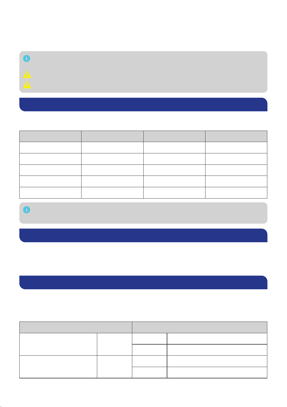
Battery Management System
The battery is equipped with a Battery Management System (BMS) that provides warnings and
protections against overvoltage, undervoltage, overcurrent, short circuit, high temperature, and
low temperature conditions. Refer to the table below for the triggering and recovery conditions of
each warning and protection.
Battery Operating Status Condition (For Reference Only)
Battery Cell Overvoltage Protection
Trigger Battery Cell Voltage ≥ 3.65V
Recover Battery Cell Voltage ≤ 3.40V
Battery Cell Undervoltage Protection
Trigger Battery Cell Voltage ≤ 2.50V
Recover Battery Voltage ≥ 3.25V

— 13 —
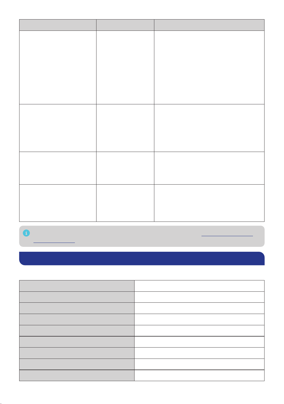
Battery Operating Status Condition (For Reference Only)
Charge High Temperature Protection
Trigger Battery Temperature ≥ 131°F (55°C)
Recover Battery Temperature ≤ 122°F (50°C)
Discharge High Temperature Protection
Trigger Battery Temperature ≥ 140°F (60°C)
Recover Battery Temperature ≤ 131°F (55°C)
Charge Low Temperature Protection
Trigger Battery Temperature ≤ 32°F (0°C)
Recover Battery Temperature ≥ 41°F (5°C)
Charge Overcurrent Protection
Trigger Charge Current ≥ 55A
Recover
Discharge Current ≥ 1A
or
Recover automatically after 60s
Discharge Overcurrent
Primary
Protection
Trigger Discharge Current ≥ 60A
Recover
Charge Overcurrent ≥ 1A
or
Recover automatically after 60s
Secondary
Protection
Trigger Discharge Current ≥ 100A
Recover
Charge Overcurrent ≥ 1A
or
Recover automatically after 60s
Short Circuit Protection
Trigger Discharge Current ≥ 600A
Recover Remove Short Circuit
Troubleshooting
Problem Possible Causes Solution
z
The battery is unable
to be activated with
a charge/discharge
current greater than 1A
z
The battery is activated
at resting voltage below
42V
Severe battery
overdischarge due
to self-discharge or
parasitic loads
Revive the battery with a battery charger
or charge controller featuring lithium
battery activation or force charging.
The battery shuts off due to
undervoltage protection.
The battery voltage
drops below the
preset threshold
Disconnect the battery from loads, and
charge the battery with a current greater
than 1A as soon as possible.
— 14 —
Problem Possible Causes Solution
The battery cuts off the
charging current due to
overvoltage protection
The battery voltage
exceeds the preset
threshold during
charging.
1. Disconnect the battery from the
charging source.
2. Reduce charge voltage by 0.2V to 0.4V
for 6 hours.
3. Attempt to fully charge the battery
again with the correct voltage setting. If
the problem persists with a lithium iron
phosphate compatible charging source
and correct voltage setting, repeat the
above steps.
The battery temperature
gets too high/low during
operation and triggers high/
low temperature protection
The battery
temperature exceeds
the preset threshold.
1. Disconnect the battery from the
charging source or loads.
2. Cool down/Warm up the battery.
3. The battery recovers from high/low
temperature protection automatically
and continues operating.
The battery is shorted
and triggers short circuit
protection.
Short circuit occurs
in the battery.
1. Remove the short circuit as soon as
possible
2. Charge the battery with a current
greater than 1A.
Charge/Discharge over-
current protection is
triggered due to too high
current passing through the
battery.
Excessive current
flows through the
battery during
charging or
discharging.
Disconnect the battery from the charging
source or loads as soon as possible.
For further assitance, contact Renogy technical support service at https://www.renogy.
com/contact-us.
Specifications
General
Battery Cell Type Lithium Iron Phosphate
Rated Capacity (0.5C, 25°C) 50Ah
Nominal Voltage 48V
Voltage Range 42.0V to 55.5V
Cycle Life (0.5C, 25°C) 6000 Cycles (80% DOD)
Dimension 15.1 × 7.6 × 9.8 in / 384 × 195 × 248 mm
Weight 51.4 lbs / 23.3 kg
Connection Method Parallel (16P)
Terminal Bolt Size M8 x 1.25 x 15 mm
— 15 —
Recommended Terminal Torque 88.5 inch·lbs to 106.2 inch·lbs / 10 N·m to 12 N·m
Protection Rating IP65
Certification MSDS, UN38.3, FCC, CE, PSE, and UKCA
Operation Parameters
Charge Voltage 54V
Maximum Continuous Charge Current 50A
Maximum Continuous Discharge Current 50A
Peak Discharge Current 100A@5s
Charge Temperature Range -4°F to 131°F / -20°C to 55°C
Discharge Temperature Range -4°F to 140°F / -20°C to 60°C
Storage Temperature Range -13°F to 149°F / -25°C to 65°C
Operation Relative Humidity 10% to 95%
Maintenance & Storage
Inspection
Please perform regular inspections following the steps below:
z
Examine the external appearance of the battery. The housing and terminals of the battery
shall be clean, dry, and free of corrosion.
z
Check battery cables and connections. Replace any damaged cables and tighten any loose
connections.
In certain application scenarios, corrosion may occur around the terminals. Corrosion
can cause increased resistance and poor contact. It is recommended to regularly apply
insulation grease to each terminal. Insulation grease can form a moisture-resistant seal
and protect the terminals from corrosion.
Cleaning
Please clean the battery at regular intervals following the steps below:
z
Disconnect the battery from the system.
z
Clear the leaves and debris from the battery.
z
Clean the battery with a soft, lint-free cloth. The cloth can be dampened with water or mild
soap and water if the battery is extremely dirty.
z
Dry the battery with a soft, lint-free cloth.
z
Keep the area around the battery clean.
z
Reconnect the battery to the system.
Checking Voltage
Please check the battery voltage periodically to assess battery health. If the battery is unable
to be activated with a charge/discharge current greater than 1A or the battery is activated with
a resting voltage below 37.5V, the battery may have been severely overdischarged due to self-
discharge or parasitic loads. Please stop using the battery until the fault can be corrected and the
battery can be charged.

— 16 —
Storage
Please follow the tips below to ensure that the battery emerges from storage in a good condition:
z
Charge the battery to 30% to 50% SOC.
z
Disconnect the battery from the system.
z
Store the battery in a well-ventilated, dry, clean area with temperatures between -13°F (-25°C)
and 149°F (65°C).
z
Do not expose the battery to direct sunlight, moisture, or precipitation.
z
Handle the battery carefully to avoid sharp impacts or extreme pressure on the battery
housing.
z
Charge the battery at least once every 3 to 6 months to prevent it from overdischarge.
z
Fully charge the battery when it is taken out of storage.
Important Safety Instructions
The manufacturer accepts no liability for any damage caused by:
z
Force majeure including fire, typhoon, flood, earthquake, war, and terrorism.
z
Intentional or accidental misuse, abuse, neglect or improper maintenance, and use under
abnormal conditions.
z
Improper installation, improper operation, and malfunction of a peripheral device.
z
Contamination with hazardous substances or radiation.
z
Alterations to the product without express written consent from the manufacturer.
General
z
Wear proper protective equipment and use insulated tools during installation and operation.
Do not wear jewelry or other metal objects when working on or around the battery.
z
Keep the battery out of the reach of children.
z
Do not dispose of the battery as household waste. Comply with local, state, and federal laws
and regulations and use recycling channels as required.
z
In case of fire, put out the fire with a FM-200 or CO2 fire extinguisher.
z
Do not expose the battery to flammable or harsh chemicals or vapors.
z
Clean the battery regularly.
z
It is recommended that all cables should not exceed 10 meters because excessively long
cables result in a voltage drop.
z
The cable specifications listed in the quick guide account for critical, less than 3% voltage
drop and may not account for all configurations.
z
Do not expose the battery to strong electrostatic fields, strong magnetic fields, or radiation.
Battery Safety
z
Please keep the battery away from water, heat sources, sparks, and hazardous chemicals.
z
Do not puncture, drop, crush, burn, penetrate, shake, strike, or step on the battery.
z
Do not open, dismantle, repair, tamper with, or modify the battery.
z
Do not touch any terminals or connectors.
z
Please make sure any battery charger or charge controller has been disconnected before
working on the battery.
z
Do not connect or disconnect terminals from the battery without first disconnecting loads.
z
Do not place tools on top of the battery.
z
Please use suitable handling equipment for safe transportation of the battery.
z
Do not insert foreign objects into the positive and negative terminals of the battery.
— 17 —
Renogy Support
To discuss inaccuracies or omissions in this quick guide or user manual, visit or contact us at:
renogy.com/support/downloads
contentservice@renogy.com
Questionnaire Investigation
To explore more possibilities of solar systems, visit Renogy Learning Center at:
renogy.com/learning-center
For technical questions about your product in the U.S., contact the Renogy technical support
team through:
renogy.com/contact-us
1(909)2877111
For technical support outside the U.S., visit the local website below:
Canada ca.renogy.com China www.renogy.cn
Australia au.renogy.com Japan renogy.jp
South Korea kr.renogy.com Germany de.renogy.com
United
Kingdom
uk.renogy.com Other Europe eu.renogy.com

— 18 —
FCC Statement
This device complies with Part 15 of the FCC Rules. Operation is subject to the following two
conditions:
(1) This device may not cause harmful interference, and
(2) This device must accept any interference received, including interference that may cause
undesired operation.
This equipment has been tested and found to comply with the limits for a Class B digital device,
pursuant to Part 15 of the FCC Rules. These limits are designed to provide reasonable protection
against harmful interference in a residential installation. This equipment generates uses and can
radiate radio frequency energy and, if not installed and used in accordance with the instructions,
may cause harmful interference to radio communications. However, there is no guarantee that
interference will not occur in a particular installation. If this equipment does cause harmful
interference to radio or television reception, which can be determined by turning the equipment
off and on, the user is encouraged to try to correct the interference by one or more of the
following measures:
(1) Orient or relocate the receiving antenna.
(2) Increase the separation between the equipment and receiver.
(3) Connect the equipment into an outlet on a circuit different from that to which the receiver is
connected.
(4) Consult the dealer or an experienced radio/TV technician for help.
FCC Radiation Exposure Statement
This equipment complies with FCC radiation exposure limits set forth for an uncontrolled
environment. This equipment should be installed and operated with minimum distance 20cm
between the radiator & your body.
Renogy aims to empower people around the world through education and distribution of
DIY-friendly renewable energy solutions.
Renogy Power Plus allows you to stay in the loop with upcoming solar energy innovations,
share your experiences with your solar energy journey, and connect with like-minded
people who are changing the world in the Renogy Power Plus community.
We intend to be a driving force for sustainable living and energy independence.
In support of this eort, our range of solar products makes it possible for you to minimize
your carbon footprint by reducing the need for grid power.
Renogy Empowered
Live Sustainably with Renogy
Did you know? In a given month, a 1 kW solar energy system will...
Save 170 pounds of coal from being burned
Save 300 pounds of CO2 from being released into the atmosphere
Save 105 gallons of water from being consumed
@Renogy Solar @Renogy@renogyocial
Renogy Power
PLUS
Renogy reserves the right to change the contents of this manual without notice.
RENOGY.COM