Loading ...
Loading ...
Loading ...

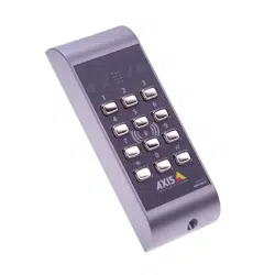
AXIS A4011-E Reader
Wire Area
NONO
NO
TICETICE
TICE
Each wire shall have an area that corresponds to an conductor gauge range of
AWG 28–16 (CSA) or AWG 22–14 (cUL/UL). Select cables in compliance with your local
regulations.
AWG
Diameter mm (in)
Area mm
2
28–16
0.321–1.29 (0.0126–0.0508)
0.0810–1.31
22–14
0.644–1.63 (0.0253–0.0641)
0.326–2.08
Tampering Alarm
The tampering alarm switch and tampering alarm sensor can toggle between an open and closed
circuit. When the reader is removed from the surface it is attached to, or when the frontplate is
removed, an alarm event is sent to the door controller. In the door controller, the alarm event can
be used to trigger an action. For information, see the door controller’s User Manual.
DIP Switches
The reader can be congured through eight DIP switches that are located on the right side of the
circuit board. To change the conguration, remove the frontplate, and then ip the DIP switches
as required. For information about card formats and reader feedback, see the door controller’s
User Manual.
DIP Default setting Function
1
OFF
Address value 1
2
OFF
Address value 2
3
OFF
Address value 4
4
OFF
Key beep: beep at keystrokes and major/minor signal
at invalid/valid card
5
OFF Card beep: beep at card read
6
OFF
n/a
7
OFF
Light on: keypad always lit
8
OFF
Light code: keypad lits when the indication for PIN code
is activated
9
Loading ...
Loading ...
Loading ...