Loading ...
Loading ...
Loading ...
-18-
Model W1843 (For Machines Mfd. Since 3/17)
SETUP
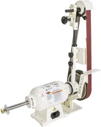
5. Slide the assembled arm brackets onto the right-
hand arbor with the arm bracket bushing facing
out, as shown in Figure 10, then secure it with the
remaining (3)
1
⁄4"-20 x
1
⁄2" cap screws.
6. Move the machine to the selected mounting surface,
and use the eight holes in the base of the motor
assembly and the pivot arm bracket assembly as a
template for drilling the mounting holes.
7. Loosen the three cap screws of the pivot arm
bracket assembly (see Figures 8–9 on Page.17),
then use the mounting hardware you have chosen to
firmly secure the motor assembly and the bracket
assembly in place.
Note: Before fully tightening the mounting
hardware, make sure that the three cap screws and
four set screws of the arm bracket assembly are
loose. This will allow the mounting bracket to lay
flat on the mounting surface.
8. Tighten the four set screws in the pivot arm bracket
assembly (see Figures 8–9.on Page.17) just until you
feel resistance. This will keep the two parts of the
assembly stable during operation.
9. Fully tighten the three cap screws on the pivot arm
bracket assembly.
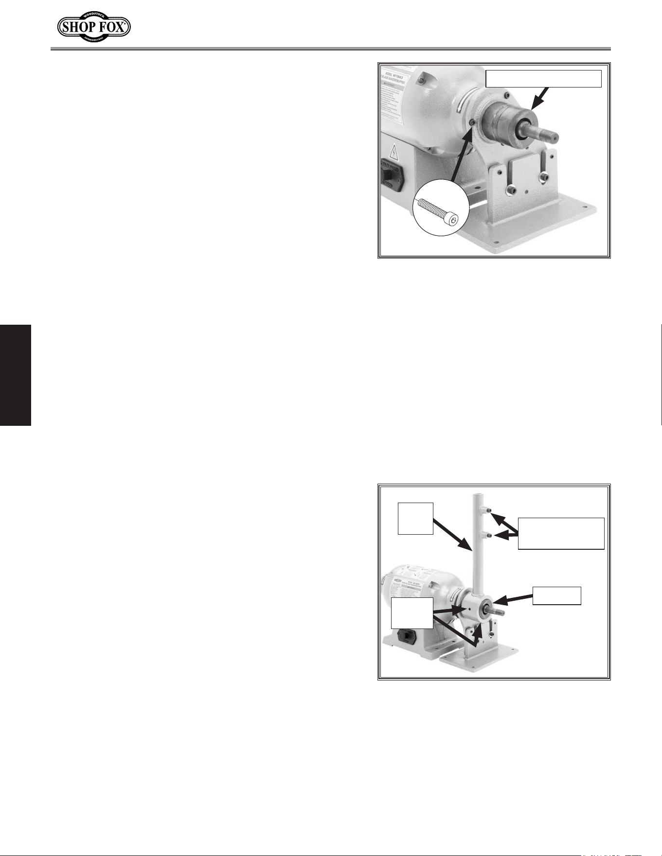
10. Back out the two set screws in the round end of the
pivot arm, slide the arm onto the bracket bushing so
that the platen bracket cap screws are facing to the
right, as shown in Figure 11, then tighten the set
screws to hold the pivot arm in place.
Note: The pivot arm and bushing are designed so
that the set screws tighten into the grooved surface
of the bushing. This keeps the pivot arm from
sliding off the bushing when using the tilt feature.
Figure 10. Pivot arm bracket assembly
installed onto the motor assembly.
x 3
Arm Bracket Bushing
Figure 11. Pivot arm installed.
Bushing
Platen Bracket
Cap Screws
Pivot
Arm
Set
Screws
Loading ...
Loading ...
Loading ...