
INSTRUCTION MANUAL
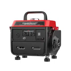
1200W 2 Stroke Portable Generator
Model # DB5010
Fuel mix ratio: 50:1
Have product questions or need technical support? Please scan the QR code to enter our official
website and contact us!
Website: www.powersmartusa.com
Toll free: 1-872-314-0005
M-F 9-5 EST
Email: support@amerisuninc.com , [email protected]
Website
(872)314-0005, Mon-fri 9-5 EST

2

3
CONTENTS
Technical data..................................................................................................
3
Introduction….................................................................................................
4
Safety information...........................................................................................
4
General safety procedures...............................................................................
5
Important safety instructions….......................................................................
6
Knowing your generator..................................................................................
7
Generator preparation......................................................................................
8
Starting the generator......................................................................................
10
Stopping the generator.....................................................................................
12
Using the generator.........................................................................................
.13
Maintenance....................................................................................................
.15
Storage & transport procedures…...................................................................
17
Troubleshooting...............................................................................................
18
Wiring diagram................................................................................................
Exploded view & parts list..............................................................................
20
Warranty..........................................................................................................
2
TECHNICAL DATA
1200W 2 Stroke Generator
Engine type: 2 stroke, single cylinder with forced air cooling system
Spark plug: F5TC
Spark plug gap: 0.7-0.8 mm (0.028-0.031 in)
Spark plug torque: 1/2-3/4 turn after gasket contacts base or 15 ft.lb
Displacement: 71 cc
Fuel tank capacity: 1.1 gallon/ 87 octaneminimum mixed with 2 stroke oil
Fuel and 2 stroke oil mix ratio 50:1
Lubrication system: Splash lubrication
AC Rated wattage: 1000W
AC Surge wattage: 1200W
AC Rated voltage: 120V
AC Rated amperage: 8.3A
Frequency: 60Hz
Phase: Single
DC Voltage: 12V
Dimensions(L x W x H):
16x14x13.8 inch
Runtime on 50%load: 5 hour
Weight:
39 lb.
Model#DB5010
2
1
3

In order to answer questions and solve problems in the most efficient and speedy manner, contact
Customer Service at (872) 314-0005, Mon-Fri 9am-5pm EST or
Email: support@amerisuninc.com ,


7
10
KNOWING YOUR GENERATOR
Use the illustrations below to become familiar with the locations and functions of the various components
and controls of this generator.
4 5 6 7 8 9
3
13
12
2
11
1
1
Air Cleaner – a removable,
cleanable, sponge-like element that
limits the amount of dirt pulled into
the engine.
8
DC Terminal
2
AC Circuit Rest Button – Reset
button that protects the generator
from AC outlet overload.
9
DC Circuit Reset Button – Reset button
that protects the generator from DC outlet
overload.
3
120 Volt AC Receptacle – To
connect electrical devices that run
on 120 Volt, 60 Hz, single phase,
AC current.
10
Ground Terminal – Connect grounding
wires here to properly ground unit.
4
Fuel Tank
11
Recoil Starter – Pull-cord for starting
engine.
5
Fuel Cap – Access to the fuel tank
for adding fuel.
12
Choke Lever – Adjusts the amount of air
let into then engine.
6
Carrying Handle – for easy
transport.
13
Fuel Valve
– Allows fuel to enter engine.
7
Engine Switch – Used to start/stop
engine.

The following section describes steps necessary to prepare the generator for use. If after reading this
section, you are unsure about how to perform any of the steps please call (872)
314
- 0005 Mon-Fri 9-5,
EST for customer service. Failure to perform these steps properly can damage the generator or shorten
its life.

9
Do not smoke near generator.
Always operate on a firm, level surface.
Always turn generator off before refueling. Allow generator to cool for at least 2 minutes before
removing fuel cap. Loosen cap slowly to relieve pressure in tank.
Do not overfill fuel tank. Gasoline may expand during operation. Do not fill to the top of the tank.
Allow for expansion.
Always check for spilled fuel before operating. Clean up any spilled fuel before starting.
Empty fuel tank before storing or transporting the generator.
Before transporting, turn fuel valve to off position and disconnect spark plug wire.
1.
Be sure generator is outdoors and in a well ventilated area.
2.
Clean the area around the fuel fill cap and remove the fuel fill cap.
3.
Using the approved red gasoline container with the gasoline and oil mixture, slowly add the fuel to
the tank. DO NOT overfill the fuel tank. Leave space for expansion.
4.
Replace the fuel cap and wipe up any spills.
Failure to properly ground the generator can result in electrocution.
Ground the generator by tightening the grounding nut on the front control panel against a
grounding wire. A generally acceptable grounding wire is a No. 12 AWG (American Wire
Gauge) stranded copper wire. This grounding wire should be connected at the other end to a copper,
brass, or steel-grounding rod that is driven into the earth. Wire and grounding rods are not included in
generator contents.
Grounding codes can vary by location. Contact a local electrician to check the area codes.
Grounding Nut
This generator may emit highly flammable and explosive gasoline vapors, which can cause
severe burns or even death if ignited. A nearby open flame can lead to explosion even if not directly in
contact with gasoline.
Do not operate near open flame.
•
•
•
•
•
•
•
•
•
WARNING:
Step 4-GROUND THE GENERATOR
WARNING:
Step 3-FILLING THE FUEL TANK
NOTE: After completing the above preparation, the generator is ready to be started.

10
STARTING THE GENERATOR
Before starting the generator, make sure you have read and performed the steps in the “Generator
Preparation” section of this manual. If you are unsure about how to perform any of the steps in this
manual, please call (871) 314-000
5, Mon-Fri 9-5 EST or email: support@amerisuninc.com /
for customer service.
DANGER: CARBON MONOXIDE.
Using a generator indoors CAN KILL YOU IN MINUTES.
Generator exhaust contains carbon monoxide (CO). This is a poison gas you cannot see or smell. If you
can smell the generator exhaust, you are breathing CO. Even if you cannot smell the exhaust, you may be
breathing CO.
NEVER use a generator inside homes, garages, crawlspaces, or other partly enclosed areas. Deadly
levels of carbon monoxide ca
n build up in these areas. Using a fan or opening windows and doors does
NOT supply enough fresh air.
ONLY use a generator outside and far away from windows, doors, and vents. These openings can pull in
generator exhaust. Even if you use a generator correctly, CO may leak into the home. ALWAYS use a
battery-powered or battery-backup CO alarm in the home.
If you start to feel sick, dizzy, or weak after the generator has been running, move to fresh air RIGHT
AWAY. See a doctor. You may have carbon monoxide poisoning.
WARNING: This generator produces powerful voltage, which can result in electrocution.
ALWAYS ground the generator before using it (see the “Ground the Generator” portion of th
e
“Generator Preparation” section).
•
Generator should only be plugged into electrical devices, either directly or with an extension cord.
NEVER connect to a building electrical system without a qualified electrician. Such connections
must comply with local electrical laws and codes. Failure to comply can create a back-feed, which
may result in serious injury or death to utility workers.
•
Use a ground fault circuit interrupter (GFCI) in highly conductive areas such as metal decking or steel
work. GFCIs are available in-line with some extension cords.
•
Do not use in rainy or wet conditions.
•
Do not touch bare wires or receptacles (outlets).
•
Do not allow children or non-qualified persons to operate.
CAUTION: Disconnect all electrical loads from the generator before attempting to start.

11
High Altitude Operation from 1640 feet to 7000 feet
At high altitude, the standard carburetor air-fuel mixture will be too rich. Performance will decrease and
fuel consumption will increase. A very rich mixture will also foul the spark plug and cause hard starting.
Operation at an altitude that differs from that at which this engine was certified, for extended periods of
time, may increase emissions.
The fuel system on this Engine or Equipment may be influenced by operation at higher altitudes. It must
install an altitude kit at altitudes from 1640ft. to 7000ft. above sea level. Kits should be installed by a
qualified individual.
WARNING: To prevent serious injury from fire: Follow the kit procedures in a well-ventilated
area away from ignition sources. If the engine is hot from use, shut the engine off and wait for it
to cool before proceeding.
NOTICE: The warranty may be void if necessary adjustments are not made for high altitude use.
NOTICE:
Even with carburetor modification, engine horsepower will decrease in high altitude. The
effect of altitude on horsepower will be greater than this if no carburetor modification is made.
STARTING THE ENGINE
OFF
ON
4. Open the Fuel Valve.(See Picture 1)
To start the generator, perform the following steps:
1. Unplug all electrical devices from the generator during ignition. Otherwise it
will be difficult for the engine to start.
2. Check that the generator is properly grounded (Refer to “GROUND THE
GENERATOR”).
3. Check the oil and fuel levels.
Picture 1
Picture 2
Picture 3
Picture 4
Picture 5
5. To start a cold engine, move the Choke to the START position.
To restart a warm engine, leave the Choke in the RUN position.(See Picture 2)
START RUN
ON
7. Grip the Starter Handle of the Engine loosely and pull it slowly
several times to allow the gasoline to flow into the Engine’s carburetor.
Then pull the Starter Handle gently until resistance is felt. Allow Cable
to retract fully and then pull it quickly. Repeat until the engine starts.(See Picture 4)
Note: Do not let the Starter Handle snap back against the engine.Hold it as
it recoils so it doesn't hit the engine.
IMPORTANT: If engine fails to start, repeat step 7. NOTE: After repeated
failed attempts to start the engine, please consult the troubleshooting guide
before attempting again.
8. Allow the Engine to run for several seconds. Then, if the Choke lever is in
the START position, move the Choke Lever very slowly to its RUN position.(See Picture 5)
Note: Moving the Choke Lever too fast could stall the engine.
IMPORTANT: Allow the engine to run at no load for five minutes after each
start-up so that the engine can stabilize.
Break-in Period:
a. Breaking-in the engine will help to ensure proper equipment and engine operation.
b. The break-in period will last about 25 hours of use.DO NOT exceed 75% of the
Generator’s rated capacity during this period.
•Change the engine fuel/oil mixture after this period.Under normal operating
conditions subsequent maintenance follows the schedule explained in the
Maintenance section.
START RUN
6. Turn the Engine Switch on.(See Picture 3)

12
Altitude kit replacement
1. Turn off the engine.
2. Close the fuel valve.
3. Place a bowl under the fuel cup to catch any spilled fuel.
4. Using a 10mm wrench, take off the fixing bolt and bolt seal (5)
from the body of the carburetor.
5. Remove the fuel cup (4) and seal (3).
6. Take off main jet (2).
7. Replace the main jet (altitude kit supplied ) with suitable one applying to altitude height.
8. Reassemble the fuel cup seal , fuel cup , bolt seal and bolt . Tighten in place.
9. Commissioning. Make sure generator works correctly after installation.
WARNING:
Wipe up any spilled fuel and allow excess to evaporate before starting engine. To
prevent fire, do not start the engine while the smell of fuel hangs in the air.
STOPPING THE GENERATOR
TO STOP THE GENERATOR
WARNING: Allow the generator to cool for several minutes before touching areas that
become hot during use.
CAUTION: Allowing gasoline to sit in the fuel tank for long periods of time can make it difficult to start
the generator in the future. Never store the generator for extended periods of time with fuel in the fuel
tank. Refer to Generator Storage Section.
Part # Description Qty
022010600103 Main jet
1
OFF
1. When finished using the appliance/tool, turn it off and unplug it from the AC Outlet on the Generator.
Picture 1
Picture 2
Picture 3
2. To stop the engine in an emergency, turn the Engine Switch off.
3. Under normal conditions, use the following procedure:
a. Remove all electrical load devices from the Generator.(See Picture 1)
b. Turn the Engine Switch off.(See Picture 2)
c. Close the Fuel Valve.(See Picture 3)

13
USING THE GENERATOR
WARNING: When this generator is used on a building’s wiring system, the generator must be installed
by a qualified electrician and connected to a transfer switch as a separately derived system in accordance
with the National Electrical Code, NFPA 70. The generator shall be connected to a transfer switch that
switches all conductors other than the equipment grounding conductor. The frame of the generator shall
be connected to an approved grounding electrode.
For power outages, permanently installed stationary generators are better suited for providing backup
power to the home. Even a properly connected portable generator can become overloaded. This may
result in overheating or stressing the machine’s components, possibly leading to a generator failure.
Before connecting electrical devices, allow the generator to run for a few minutes to stabilize the speed
and voltage output.
CAUTION: Become familiar with the markings on the panel before connecting electrical devices.
AC Usage
Connect electrical devices running on AC current according to their wattage requirements. The chart
below shows the rated and surge wattage of the generator.
Model Rated Wattage Surge Wattage
DB5010
1000W 1200W
The rated (running) wattage is the wattage the generator can produce on a continuous basis.
The surge wattage is the maximum amount of power the generator can produce for an extremely short
period of time (seconds). Many electrical devices such as refrigerators require short bursts of extra power
in addition to the rated wattage listed by the device to start their motors. The surge wattage ability of the
generator covers this extra power requirement.
The total running wattage requirement of the electrical devices connected to the generator should not
exceed the rated wattage of the generator itself. To calculate the total wattage requirement of the
electrical devices you plan to connect, find the rated (or running) wattage of each device. This number
should be listed somewhere on the device or in its instruction manual. If this wattage cannot be found,
calculate it by multiplying the Voltage requirement by the Amperage drawn:
Watts = Volts x Amperes
If these specifications are not available, estimate the wattages requirement of the device by using the
chart in next page.
When the rated wattage requirement of each electrical device has been determined, add these numbers to
find the total rated wattage needed. If this number exceeds the rated wattage of the generator, DO NOT
connect all these devices. Select a combination of electrical devices, which have a total rated wattage
lower than or equal to the rated wattage of the generator.
CAUTION: The generator can run at its surge wattage capacity for only a short time. Connect electrical
devices requiring a rated (running) wattage equal to or less than the rated wattage of the generator. Never

14
connect devices requiring a rated wattage equal to the surge wattage of the generator. This can trip the
circuit protectors (circuit breakers).
Tool or appliance Rated watts Additional surge watts
Electric water heater (40 Gal) 4000 0
Hot plate
2500
0
Radial arm saw
2000
2000
Electric stove (each element) 1500-2800 0
Circular saw
1500
1500
Air compressor (1 HP) 1500 3000
Window air conditioner 1200 1800
Miter saw
1200
1200
Microwave
1000
0
Well water pump
1000
1000
Reciprocating saw 960 1040
Sump pump 800 1200
Refrigerator freezer
800
1200
Furnace blower 800 1300
Computer 800 0
Electric drill
600
900
Television 500 0
Deep freezer 500 500
Garage door opener
480
0
Stereo 400 0
Box fan
300
600
Clock radio
300
0
Security system
180
0
DVD player
100
0
Common light bulb 75 0
Estimated wattage requirements of common electrical devices
Note: The above wattage figures are estimates. Check the wattage listed on the electrical device before
consulting this chart. Once the electrical devices that will be powered by the generator have been
determined, connect these devices.
Once you have determined what electrical devices you will be powering with the generator, connect these
devices according to the following procedure:
1.
Plug in each electrical device with the device turned off. NOTE: Be sure to attach appliances to the
correct receptacles (outlets).
2.
Push in the circuit reset buttons to the “on” position (NOTE: They may be already pushed in which is
the “on” position).
3.
Start each appliance/device one at a time. Do not overload the capacity of the generator.
CAUTION: Do not connect 50Hz loads to the generator.
SOME NOTES ABOUT POWER CORDS
Long or thin cords can drain the power provided to an electrical device by the generator. When using
such cords, allow for a slightly higher rated wattage requirement by the electrical device. See below for
recommended cords based on the power requirement of the electrical device.

1. Clean fuel tank, strainer
and carburetor
2. Clean carbon build-up
from combustion chamber
Replace fuel line if
necessary

16
AIR CLEANER MAINTENANCE
Routine maintenance of the air cleaner helps maintain proper airflow to the carburetor. Occasionally
check that the air cleaner is free of excessive dirt. Refer to Recommended Maintenance Schedule in last
page. For air cleaner detail:
1.
Undo the 2 bolts holding the air cleaner cover in place.
2.
Remove the sponge-like elements from the casing.
3.
Wipe the dirt from inside the empty air cleaner casing
4.
Wash the sponge-like elements in household detergent and warm
water. Allow to dry.
5.
Drip the sponge-like element in clean engine oil, squeeze outextra
oil and reinsert into the casing.
6.
Attach the air cleaner cover with the 2 bolts.
Air Cleaner Cover
CAUTION: running the engine with dirty, damaged or missing air cleaner element will cause the engine
to wear out prematurely.
SPARK PLUG MAINTENANCE
The spark plug is important for proper engine operation. A good spark plug should be intact, free of
deposits, and properly gapped. Refer to Recommended Maintenance Schedule. To inspect the spark plug:
1.
Remove spark plug boot. Be careful not to tear insulation or wire.
2.
Unscrew the spark plug from the engine using the spark plug wrench provided. There is limited space
for the wrench to turn. Use both rows of holes in the spark plug wrench to gain leverage to loosen the
plug.
3.
Visually inspect the spark plug for cracks or excessive electrode wear. Replace as necessary.
4.
Measure the plug gap with a wire gauge. The gap should be 0.7 to 0.8 mm (0.028-0.031 in).
5.
If re-using the spark plug, use a wire brush to clean any dirt from around the spark plug base then
re-gap the spark plug.
6.
Screw the spark plug back into the spark plug hole using the spark plug wrench. Do not over-tighten
spark plug. Recommended tightening of spark plug is ½ to ¾ of a turn after spark plug gasket contacts
spark plug hole. Reinstall the spark plug boot.
DRAINING THE FUEL TANK
Clean fuel tank each year or before storing the generator for extended periods of time. To drain the fuel
tank and carburetor:
1.
Turn the fuel valve to the “OFF” position.
2.
Remove the fuel line between the fuel valve and carburetor. Caution: A small amount of fuel may
leak from the hose during removal.
3.
Attach a fuel line (not included with the generator) to the exposed end of the fuel valve.
4.
Position fuel line into an appropriate container and open the fuel valve allowing fuel to flow into the
container.
5.
Once fuel is drained, shut off the fuel valve.
6.
Start and run the engine until fuel runs out.
7.
Store the emptied gasoline in a suitable place.
CAUTION: Do not store fuel for more than 3 months.

17
STORAGE & TRANSPORT PROCEDURES
CAUTION: Never place any type of storage cover on the generator while it is still hot.
If the generator is being stored for short periods of time (30 to 60 days), add stabilized fuel to the fuel tank
until full. NOTE: Filling the tank reduces the amount of air in the tank and helps reduce deterioration of
fuel. Run the engine for 2 – 3 minutes allowing stabilized fuel mixture to circulate through the carburetor.
When storing the generator for extended periods of time:
•
Drain the fuel tank (see “Draining the Fuel Tank” in the “Maintenance” section).
•
Change oil.
•
Do not obstruct any ventilation openings.
•
Keep the generator in a cool dry area.
When transporting generator:
•
Drain the fuel tank if possible (see “Draining the Fuel Tank” in the “Maintenance” section).
•
Keep the generator upright. Never place the generator side down. Doing so will make it difficult to
start.

18
Engine will not start
FUEL RELATED:
1. No fuel in tank or fuel valve
closed.
2. Choke not in START position,
cold engine.
3. Gasoline with more than 10%
ethanol used. (E15, E20, E85,
etc.)
4. Low quality or deteriorated,
old gasoline/oil mixture.
5. Dirty fuel passageways.
6. Carburetor needle stuck.
Fuel can be smelled in the air.
7. Too much fuel in chamber.
This can be caused by the
carburetor needle sticking.
8. Clogged Fuel Filter.
FUEL RELATED:
1. Fill fuel tank with 87+ octane stabilizer-treated
unleaded gasoline/oil mixture and open fuel valve.
2. Move Choke to START position.
3. Clean out ethanol rich gasoline from fuel system.
Replace components damaged by ethanol. Use fresh
87+ octane stabilizer-treated unleaded gasoline/oil
mixture only.
Do not use gasoline with more than 10% ethanol
(E15, E20, E85, etc.).
4. Use fresh 87+ octane stabilizer-treated unleaded
gasoline/oil mixture.
Do not use gasoline with more than 10% ethanol
(E15, E20, E85, etc.).
5. Clean out passageways using fuel additive. Heavy
deposits may require further cleaning.
6. Gently tap side of carburetor float chamber with
screwdriver handle.
7. Turn Choke to RUN position. Remove spark plug and
pull the start handle several times to air out the
chamber. Reinstall spark plug and set Choke to
START position.
8. Replace Fuel Filter.
IGNITION (SPARK) RELATED:
1. Spark plug cap not connected
securely.
2. Spark plug electrode wet or
dirty.
3. Incorrect spark plug gap.
4. Spark plug cap broken.
5. Incorrect spark timing or faulty
ignition system.
IGNITION (SPARK) RELATED:
1. Connect spark plug cap properly.
2. Clean spark plug.
3. Correct spark plug gap.
4. Replace spark plug cap.
5. Have qualified technician diagnose/repair ignition
system.
COMPRESSION RELATED:
1. Cylinder not lubricated.
Problem after long storage
periods.
2. Loose or broken spark plug.
(Hissing noise will occur when
trying to start.)
3. Loose cylinder head or
damaged head gasket.
(Hissing noise will occur when
trying to start.)
COMPRESSION RELATED:
1. Pour tablespoon of oil into spark plug hole. Crank
engine a few times and try to start again.
2. Tighten spark plug.
If that does not work, replace spark plug.
If problem persists, may have head gasket problem, see
#3.
3. Tighten head.
If that does not remedy problem, replace head gasket.
Problem Possible Causes Probable Solutions
Engine misfires 1. Spark plug cap loose.
2. Incorrect spark plug gap or
damaged spark plug.
3. Defective spark plug cap.
4. Old or low quality gasoline/oil
mixture.
5. Incorrect compression.
1. Check wire connections.
2. Re-gap or replace spark plug.
3. Replace spark plug cap.
4. Use only fresh 87+ octane stabilizer-treated
unleaded gasoline/oil mixture.
Do not use gasoline with more than 10% ethanol
(E15, E20, E85, etc.).
5. Diagnose and repair compression. (Use Engine will
not start: COMPRESSION RELATED section.)
TROUBLESHOOTING

Engine stops
suddenly
1. Fuel tank empty or full of
impure or low quality
gasoline/oil mixture.
2. Defective fuel tank cap
creating vacuum,
preventing proper fuel flow.
3. Faulty magneto.
4. Disconnected or improperly
connected spark plug cap.
1. Fill fuel tank with fresh 87+ octane stabilizer-treated
unleaded gasoline/oil mixture.
Do not use gasoline with more than 10% ethanol
(E15, E20, E85, etc.).
2. Test/replace fuel tank cap.
3. Have qualified technician service magneto.
4. Secure spark plug cap.
Engine stops when
under heavy load
1. Dirty air filter
2. Engine running cold.
1. Clean element.
2. Allow engine to warm up prior to operating
equipment.
Engine knocks 1. Old or low quality gasoline/oil
mixture.
2. Engine overloaded.
3. Incorrect spark timing, deposit
buildup, worn engine, or other
mechanical problems.
1. Fill fuel tank with fresh 87+ octane stabilizer-treated
unleaded gasoline/oil mixture.
Do not use gasoline with more than 10% ethanol
(E15, E20, E85, etc.).
2. Do not exceed equipment’s load rating.
3. Have qualified technician diagnose and service
engine.
Engine backfires 1. Impure or low quality
gasoline/oil mixture.
2. Engine too cold.
3. Incorrect timing.
1. Fill fuel tank with fresh 87+ octane stabilizer-treated
unleaded gasoline/oil mixture.
Do not use gasoline with more than 10% ethanol
(E15, E20, E85, etc.).
2. Use cold weather fuel additives to prevent backfiring.
3. Check engine timing.
Attached device
Generator runs but
doesn’t support all
electrical devices
connected.
doesn’t have power
1. Device not plugged in
1.Generator is overloaded.
properly.
2. Circuit Breaker tripped.
3. Bad connecting wires/cables.
6. Product needs service.
1. Turn off and unplug the device,
Perform these steps:
1. Turn off all electrical devices.
2. Unplug all electrical devices.
3. Turn off generator.
4. Wait several minutes.
5. Restart generator.
6. Try to connect fewer electricalloads
to the generator.
1.Short in one of the connected
devices.
1.Try disconnecting any faulty or short-circuited
electrical loads.
1.Air cleaner is dirty. 1.Clean or replace air cleaner.
then plug it back in again and turn on.
2. Turn off and unplug device, Wait for 2 minutes and
move the circuit breaker button to the "ON" position,
Plug in device and turn on.
3. If you are using an extension cord, try a different one.
4. Capacitance is broken
4. Replace Capacitance
5. Bad electrical device
connected to generator
5. Try connecting a different device.
6. Have product repaired.
Attached device
begins to operate
abnormally
1. Problem with device.
1. Immediately unplug device.
Have device repaired by a qualified technician, or
replace device.
Problem Possible Causes Probable Solutions
Follow all safety precautions whenever diagnosing or servicing the generator or engine.
19

20
WIRING DIAGRAM

21
EXPLODED VIEW AND PARTS LIST

22
Item STOCK # DESCRIPTION QTY Item STOCK # DESCRIPTION QT
Y
1
DB5010-001
3
44 DB5010-044 Cylinder head
1
2
DB5010-002
2
45 DB5010-045 Cylinder gasket
1
3
DB5010-003
7
46 DB5010-046 First piston ring
1
4
DB5010-004
3
47 DB5010-047 Second piston ring
1
5
DB5010-005
1
48 DB5010-048 Piston
1
6
DB5010-006
1
49 DB5010-049 Piston pin
1
7
DB5010-007
2
50 DB5010-050 Right crankcase
1
8
DB5010-008
1
51 DB5010-051 Clamp
1
9
DB5010-009
1
53 DB5010-052 Recoil starter assembly
1
10
2
54 DB5010-053 Flange nut M10*1.25
1
11
4
52 DB5010-054 Flywheel
1
12
2
55 DB5010-055 Bolt M6x16
2
13
1
56 DB5010-056 Ignition coil assembly
1
15
1
57 DB5010-057 Flange bolt M6x45
4
14
1
58 DB5010-058 Nut M6
4
16
1
59 DB5010-059 Absorber
4
17
1
60 DB5010-060 Bolt M6x40
1
18
2
61 DB5010-061 Compression spring
1
19
1
62 DB5010-062 Supporting plate
1
20
1
63 DB5010-063 Roller bearing 14x10x13
1
21
1
64 DB5010-064 Intake valve gasket
1
22
2
65 DB5010-065 Intake valve assembly
1
23
1
66 DB5010-066 Flange bolt M6x18
4
24
1
67 DB5010-067 Stub AM6x60
2
25
2
68 DB5010-068 Intake gasket
1
26
1
69 DB5010-069 Carburetor
1
27
2
70 DB5010-070 Carburetor gasket B
1
28
4
71 DB5010-071 Control panel
1
29
1
72 DB5010-072 Carburetor gasket A
1
30
2
73 DB5010-073 Fuel tank
1
31
1
74 DB5010-074 Fuel switch
1
32
1
75 DB5010-075 Fuel filter
1
33
2
76 DB5010-076 Fuel cup
1
34
2
77 DB5010-077 Fuel tank cap
1
35
1
78 DB5010-078 Carrying handle
1
36
2
37
1
80 DB5010-080 Bolt M6x30
2
38
2
81 DB5010-081 Capacitor
1
39
2
82 DB5010-082 Screw ST4.2x14
1
40
2
83 DB5010-083 Tension spring
1
41
1
84 DB5010-084 Rod link
1
42
1
85 DB5010-085 Governor spring
1
43
1
Flange bolt M6x80
Flange bolt M6x10
Spring washer 6
Washer 6
Breaker
Tarpaulin
Bolt M3x16
DC receptacle
Rear cover
DB5010-010 Washer 3
DB5010-011 Spring washer 3
DB5010-012 Nut M3
DB5010-013 Flange bolt M8x160
DB5010-014 Muffler
DB5010-015 Muffler gasket
DB5010-016 Alternator rotor
DB5010-017 Alternator stator
DB5010-018 Oil seal 20x30x7
DB5010-019 Left crankcase
DB5010-020 Governor arm
DB5010-021 Oil seal 6x12x4
DB5010-022 Bearing 6004
DB5010-023 Governor shaft
DB5010-024 Governor fork
DB5010-025 Bolt M3x8
DB5010-026 Hole circlip 42
DB5010-027 Pin 10x7x14
DB5010-028 Flange bolt M6x16
DB5010-029 Collar bush
DB5010-030 Stub AM6x50
DB5010-031 Weight comp
DB5010-032
DB5010-033 Circlip
Crankshaft assembly
DB5010-034 Flange bolt M6x16
DB5010-035 CDI winding
DB5010-036 Flange bolt M6*12 10 79 DB5010-079 Washer 6
DB5010-037 Head cover
DB5010-038 Bolt M6x18
DB5010-039 Stub AM6x100
DB5010-040 Flange bolt M6x105
DB5010-041 Spark plug
DB5010-042 Cylinder cap
DB5010-043 Cylinder cap gasket

23
TWO (2) YEARS LIMITED WARRANTY
PowerSmart is committed to building tools that are dependable for years. Our warranties are consistent with our
commitment and dedication to quality.
TWO (2) YEARS LIMITED WARRANTY OF POWER SMART PRODUCTS FOR HOME USE.
PowerSmart (“Seller") warrants to the original purchaser only, that all PowerSmart consumer power tools will be
free from defects in material or workmanship for a period of two (2) years from date of purchase. Ninety (90) days
for all PowerSmart Products, if the tool is used for professional or commercial use.
SELLER’S SOLE OBLIGATION AND YOUR EXCLUSIVE REMEDY under this Two (2) Years Limited
Warranty and, to the extent permitted by law, any warranty or condition implied by law, shall be the repair or
replacement of parts, without charge, which are defective in material or workmanship and which have not been
misused, carelessly handled, or misrepaired by persons other than Seller or Authorized Service Center. To make a
claim under this Limited Warranty, you must return the entire power tool product; transportation prepaid, to
PowerSmart Include a legible copy of the original receipt, which lists the date of purchase (month and year) and the
name of the company purchased from.
THIS LIMITED WARRANTY DOES NOT APPLY TO ANY ACCESSORY ITEMS INCLUDED WITH THE
TOOL SUCH AS CIRCULAR SAW BLADES OTHER RELATED ITEMS OR TO ANY REPLACEMENT
PARTS LISTED UNDER MAINTENANCE.
ANY IMPLIED WARRANTIES SHALL BE LIMITED IN DURATION TO TWO (2) YEARS FROM DATE OF
PURCHASE. SOME STATES IN THE U.S. AND SOME CANADIAN PROVINCES DO NOT ALLOW
LIMITATIONS ON HOW LONG AN IMPLIED WARRANTY LASTS, SO THE ABOVE LIMITATION MAY
NOT APPLY TO YOU.
IN NO EVENT SHALL SELLER BE LIABLE FOR ANY INCIDENTAL OR CONSEQUENTIAL DAMAGES
(INCLUDING BUT NOT LIMITED TO LIABILITY FOR LOSS OF PROFITS) ARISING FROM THE SALE
OR USE OF THIS PRODUCT. SOME STATES IN THE U.S. AND SOME CANADIAN PROVINCES DO NOT
ALLOW THE EXCLUSION OR LIMITATION OF INCIDENTAL OR CONSEQUENTIAL DAMAGES, SO
THE ABOVE LIMITATION OR EXCLUSION MAY NOT APPLY TOYOU.
THIS LIMITED WARRANTY GIVES YOU SPECIFIC LEGAL RIGHTS, AND YOU MAY ALSO HAVE
OTHER RIGHTS WHICH VARY FROM STATE TO STATE IN THE U.S., PROVINCE TO PROVINCE IN
CANADA AND FROM COUNTRY TO COUNTRY.
For questions / comments, technical assistance or repair parts –
Please call toll free at: 1-872-314-0005
(M-F 9am – 5pm EST)
SAVE YOUR RECEIPTS. THIS WARRANTY IS VOID WITHOUT THEM.