1
INSTRUCTION MANUAL
1500W Inverter Generator
Model # PS55
Have product questions or need technical support? Please scan the QR code to enter our official website
and contact us!
Website:www.powersmartusa.com
Toll free: 1-800-791-9458 M-F 9-5 EST
Email: [email protected]
Website

2

3
CONTENTS
Technical data…….……………………………………………………… 3
Introduction…….………………………………………………………… 4
Safety information…….………………………………………………..... 4
General safety rules ……....……………………………………………… 5
Important safety instructions……………………………………………... 6
Symbols………………………………………………………………….. 7
Knowing your generator…………………………………………………. 8
Generator preparation…………………………………………………..... 11
Starting the generator………....………………………………………… 15
Using the generator……………………………………………………... 16
Stopping the generator…………………………………………………... 17
Maintenance……………………………………………………………... 17
Storage & transport procedures…………………………………………. 21
Troubleshooting…………………………………………………………. 22
Wiring diagram…………………………………………………………. 23
Exploded view & parts list……………………………………………… 24
Warranty statement……………………………………………………… 28
TECHNICAL DATA
1500W Inverter Generator Model#PS55
Engine type: 4 stroke, OHV, single cylinder with forced
air-cooling system
Start type: Manual
Phase: Single
Rated wattage: 1000 W
Starting wattage: 1500 W
Rated voltage: 120 V
Rated current: 8.3 A
Rated frequency: 60 Hz
Displacement: 56 cc
Continue Running Time: 4 hours
Spark plug gap: 0.6-0.8 mm (0.024-0.031 in.)
Fuel tank capacity: 0.74 Gallon
Engine Oil capacity: 9.47 Fl.oz
USB output voltage: 5V
Package dimensions(L x W x H): 13.2x12.9x12 inches
Weight: 26.5 lbs
4
INTRODUCTION
Thank You for Purchasing a PowerSmart® Product. This manual provides information regarding the safe
operation and maintenance of this product. Every effort has been made to ensure the accuracy of the
information in this manual. PowerSmart® reserves the right to change this product and specifications at any
time without prior notice.
Please keep this manual available to all users during the entire life of the generator.
This manual contains special messages to bring attention to potential safety concerns, generator
damage as well as helpful operating and servicing information. Please read all the information
carefully to avoid injury and machine damage.
QUESTIONS? PROBLEMS?
Please contact our Customer Service Dept. with any questions and/or comments, either by Email:
help solve any issues that you might encounter.
NOTICE REGARDING EMISSIONS
Engines that are certified to comply with U.S. EPA emission regulations for SORE (Small Off Road
Equipment), are certified to operate on regular unleaded gasoline, and may include the following emission
control systems: (EM) Engine Modifications and (TWC) Three-Way Catalyst (if so equipped).
SAFETY INFORMATION
Before operating this generator, read and observe all warnings, cautions, and instructions on the
generator and in this Owner’s Manual.
NOTE: The following safety information is not meant to cover all possible conditions and situations that
may occur. Read the entire Owner’s Manual for safety and operating instructions. Failure to follow
instructions and safety information could result in serious injury or death.
This safety alert symbol is used to identify safety information about hazards that can result in personal
injury.
A signal word (DANGER, WARNING, or CAUTION) is used with the alert symbol to
indicate the likelihood and the potential severity of injury. In addition, a hazard symbol may
be used to represent the type of hazard.
DANGER Indicates a hazard, which, if not avoided, will result in death or serious injury. WARNING
Indicates a hazard, which, if not avoided, could result in death or serious injury. CAUTION Indicates a
hazard, which, if not avoided, might result in minor or moderate injury. CAUTION when used without
the alert symbol, indicates a situation that could result in damage to the
engine or generator.
5
GENERAL SAFETY RULES
For any questions regarding the hazard and safety notices listed in this manual or on the product, please
call (800) 791-9458, Mon-Fri 9-5 EST before using the generator. Please read and understand the
instructions in this manual before starting the engine or attempting to operate this unit.
DANGER: CARBON MONOXIDE
Using a generator indoors CAN KILL YOU IN MINUTES. Generator exhaust contains carbon monoxide
(CO). This is a poison gas you cannot see or smell. If you can smell the generator exhaust, you are
breathing CO. But even if you cannot smell the exhaust, you could be breathing CO.
NEVER use a generator inside homes, garages, crawlspaces, or other partly enclosed areas. Deadly levels of
carbon monoxide can build up in these areas. Using a fan or opening windows and doors does NOT
supply enough fresh air. ONLY use a generator outside and far away from windows, doors, and vents.
These openings can pull in generator exhaust.
Even if you use a generator correctly, CO may leak into the home. ALWAYS use a battery-powered or
battery-backup CO alarm in the home. If you start to feel sick, dizzy, or weak after the generator has been
running, move to fresh air RIGHT AWAY. See a doctor. You may have carbon monoxide poisoning.
WARNING: The exhaust from this product contains chemicals known to the State of
California to cause cancer, birth defects, or other reproductive harm.
WARNING: This generator may emit highly flammable and explosive gasoline vapors,
which can cause severe burns or even death if ignited. A nearby open flame can lead to
explosion even if it isn’t directly in contact with gasoline.
Do not operate near open flame.
Do not smoke near generator.
Always operate on a firm, level surface.
Always turn generator off before refueling. Allow generator to cool for at least 2 minutes before
removing fuel cap. Loosen cap slowly to relieve pressure in tank.
Do not overfill fuel tank. Gasoline may expand during operation. Do not fill to the top of the tank.
Allow for expansion.
Always check for spilled fuel before operating.
Empty fuel tank before storing or transporting the generator.
WARNING: This generator produces powerful voltage, which can result in electrocution.
ALWAYS ground the generator before using it (see the “Generating set ground” portion of
the “GENERATOR PREPARATION” section).
Generator should only be plugged into electrical devices, either directly or with an extension cord.
NEVER connect to a building electrical system without a qualified electrician. Such connections must
comply with local electrical laws and codes. Failure to comply can create a back-feed, which may result in
serious injury or death to utility workers.
Use a ground fault circuit interrupter (GFCI) in highly conductive areas such as metal decking or
steel work. GFCIs are available in-line with some extension cords.
Do not use in rainy conditions.
Do not touch bare wires or receptacles (outlets).
Do not allow children or non-qualified persons to operate.
6
WARNING: This generator produces heat when running. Temperatures near exhaust can
exceed 150℉ (65℃).
Do not touch hot surfaces. Pay attention to warning labels on the generator identifying hot parts of the
machine.
Allow generator to cool down after use before touching engine or areas of the generator that become hot
during use.
CAUTION: Misuse of this generator can damage it or shorten its life.
Only use generator for its intended purposes.
Operate only on dry, level surfaces.
Allow generator to run for several minutes before connecting electrical devices.
Shut off and disconnect any malfunctioning devices from generator.
Do not exceed the wattage capacity of the generator by plugging in more electrical devices than the unit
can handle.
Do not turn on electrical devices until after they are connected to the generator.
Turn off all connected electrical devices before stopping the generator.
Turn the engine switch to “OFF” position when the engine is not running.
IMPORTANT SAFETY INSTRUCTIONS
SAVE THESE INSTRUCTIONS – This manual contains important instructions for the PowerSmart®
1500W generator that should be followed during installation and maintenance of the generator.
Generators vibrate in normal use. During and after the use of the generator, inspect both the generator as
well as extension and power supply cords for damage resulting from vibration. Have damaged items
repaired or replaced as necessary. Do not use plugs or cords that show signs of damage such as broken or
cracked insulation.
For power outages, permanently installed stationary generators are better suited for providing backup
power to the home. Even a properly connected portable generator can become overloaded. This may
result in overheating or stressing of the components, possibly leading to a generator failure.
WARNING: If this generator is used as a supply for a building’s wiring system, the generator
must be installed by a qualified electrician and connected to a transfer switch as a separately
derived system in accordance with the National Electrical Code, NFPA 70. The generator
shall be connected to a transfer switch that switches all conductors excluding the equipment grounding
conductor. The frame of the generator shall be connected to an approved grounding electrode.
7
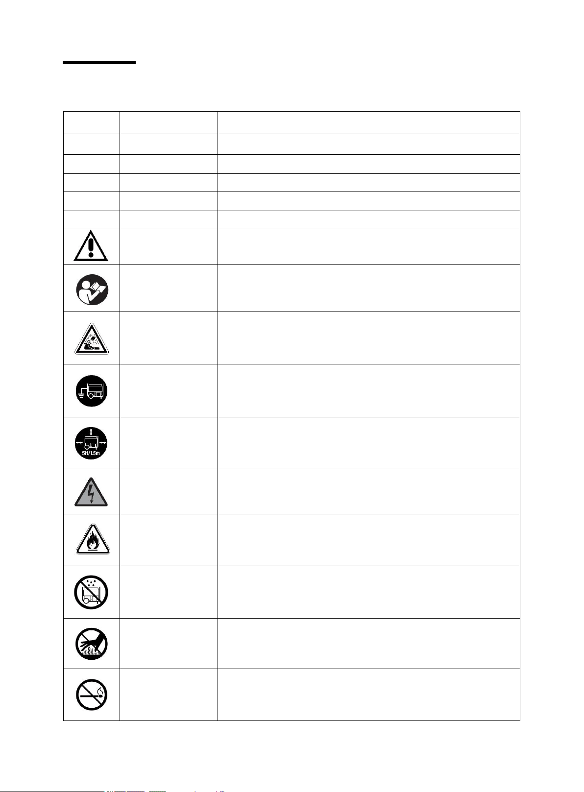
SYMBOLS
Some of the following symbols may be used on this product. Please study them and learn their meaning.
Proper interpretation of these symbols will allow you to operate the product better and safer.
SYMBOL
NAME
DESIGNATION/EXPLANATION
V
Volts
Voltage
A
Amperes
Current
Hz
Hertz
Frequency (cycles per second)
W
Watts
Power
MIN
Minutes
Time
Safety Alert
Precautions that involve your safety.
Read the user’s
manual
To reduce the risk of injury, user must read and understand user’s
manual before using this product.
Carbon monoxide
hazard
Never operate the generator in an enclosed area. Engine exhause
contains carbon monoxide. Only operate the generator outside
and away from windows, doors and vents.
Ground
Consult with local electrician to determine grounding
requirements before operation.
Clearance
Keep all objects at least 5 feet (1.5m) from generator. Heat from
the muffler and exhaust gas can ignite combustible objects.
Electric shock alert
Beware of electric shock hazard.
Fire/Explosion
Fuel and its vapors are extremely flammable and explosive. Fire
or explosion can cause severe burns or death. Keep generator at
least 5 feet (1.5m) from all objects to prevent combustion.
Wet conditions
alert
Do not expose to rain or use in damp locations.
Hot Surface
To reduce the risk of injury or damage, avoid contact with any hot
surface.
Open Flame Alert
Fuel and its vapors are extremely flammable and explosive. Keep
fuel away from smoking, open flames, sparks, pilot lights, heat,
and other ignition sources.
8
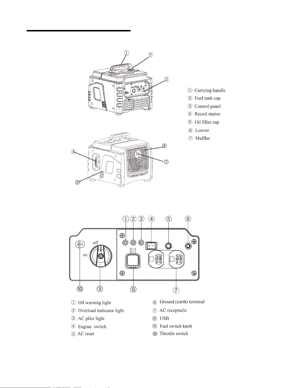
KNOWING YOUR GENRATOR
Use the illustrations below to become familiar with the locations and functions of the various components
and controls of this generator
.
Control Panel
9
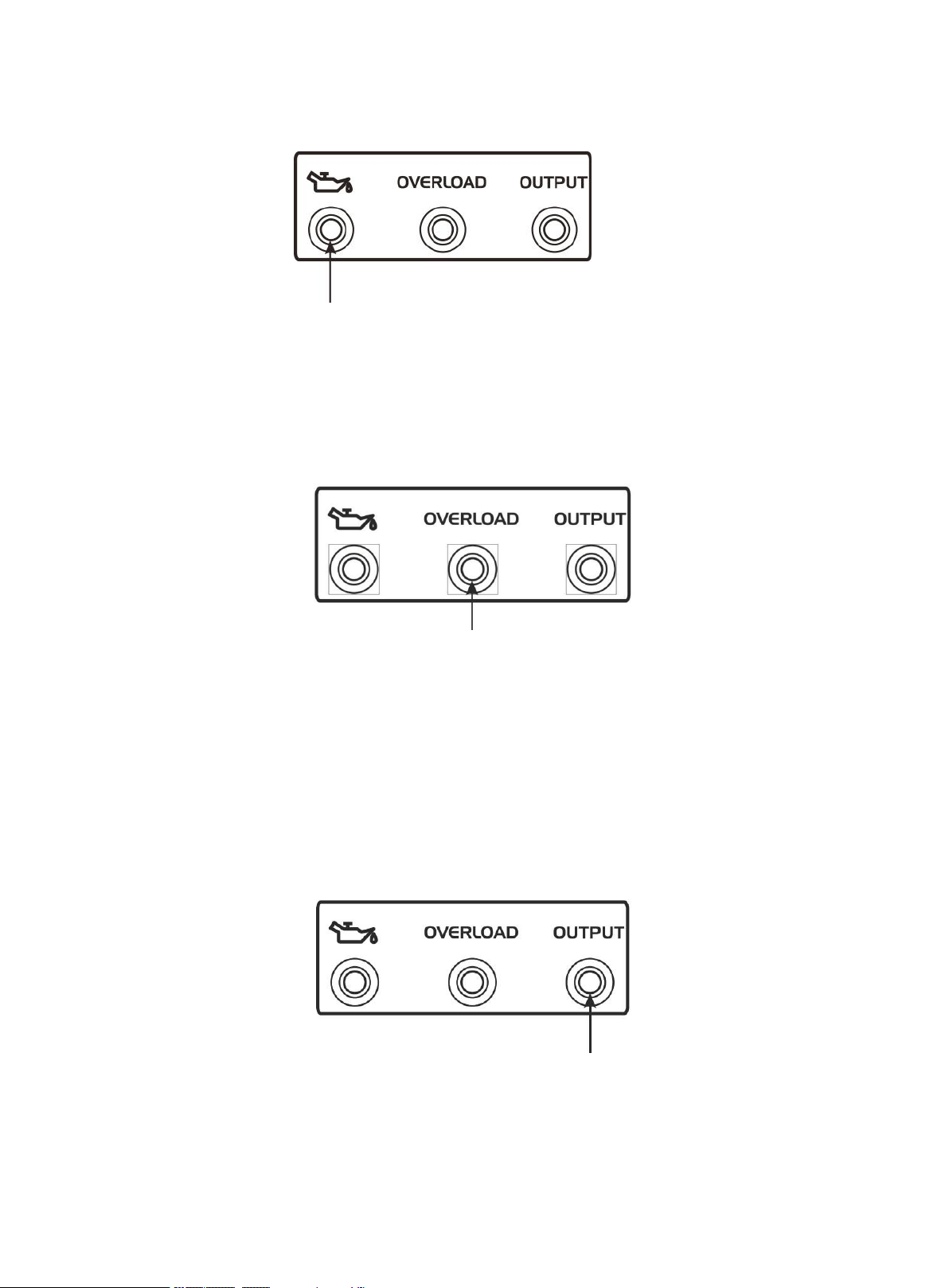
Oil warning light (red)
When the oil level falls below the lower level, the oil warning light comes on and then the engine stops
automatically. Unless you refill with oil, the engine will not start again.
Tip: If the engine stalls or does not start, turn the engine switch to "ON" and then pull the recoil starter.
If the oil warning light flickers for a few seconds, the engine oil is insufficient. Add oil and restart.
Overload indicator (red)
When the overload indicator is on, it indicates that the generating set is overload and then the AC
protector works. It will stop the output of generating set to protect the electric equipment and the
generating set itself. At this time, the running indicator (green) is off and the overload indicator (red) is on,
but the engine is still in running state.
When the generating set has no output and the overload indicator is on, please take the following steps:
1. Lower the total power of the connected electric devices to the rated output range of generating set.
2. Check the air intake for impurities and check the control parts for abnormal situation. Handle
immediately if necessary.
3. Press the reset button.
Running indicator (green)
The output indicator lights up when generating set starts and has normal output.
Note: If engine flames out or fails to start, turn the combination switch to “RUN” position and then pull
the recoil starter. If the oil alarming lamp lights up, it shows lack of oil. Please add appropriate oil and
restart the engine.
10
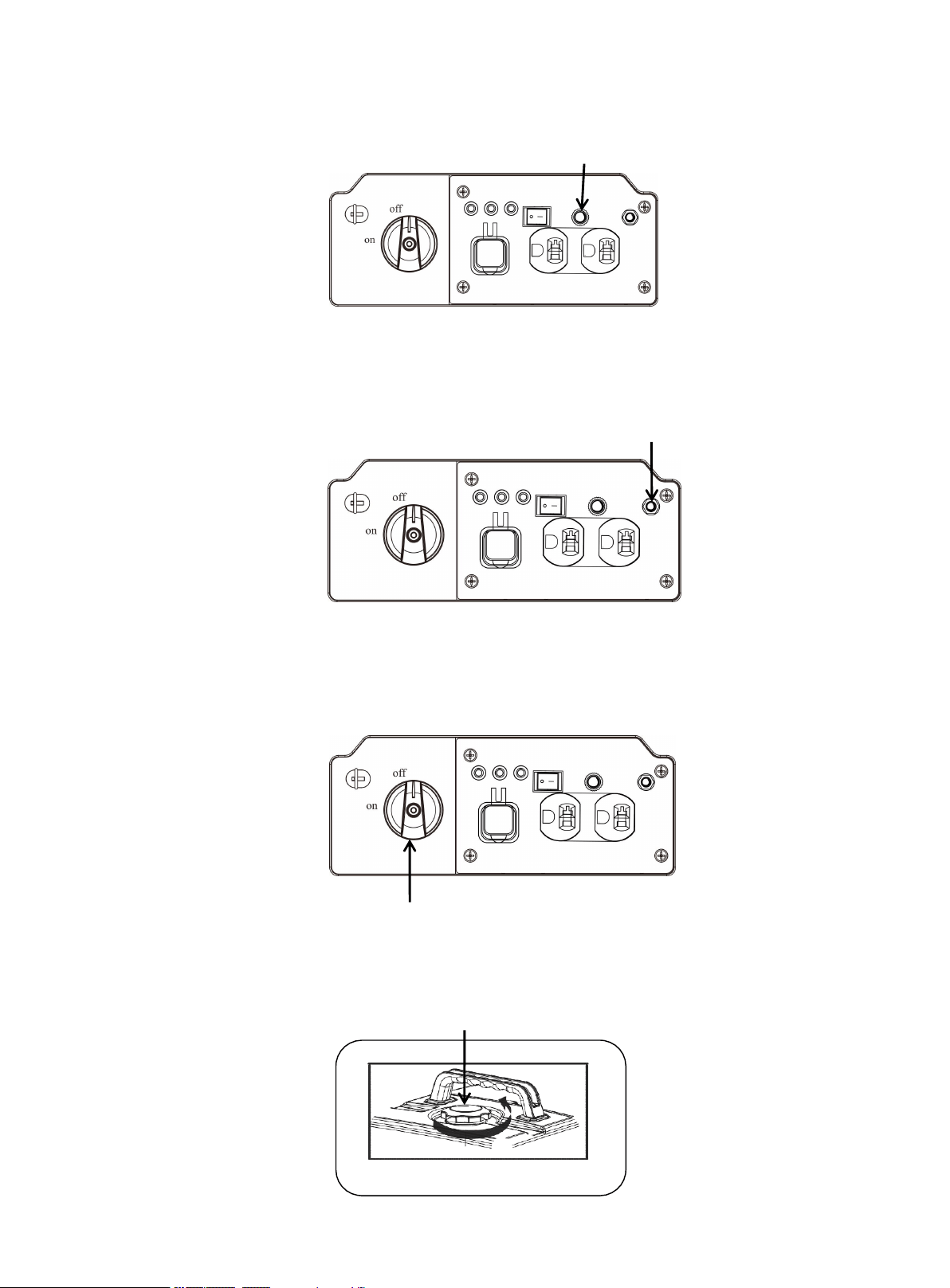
Reset button
The reset button is used to restore output if an overload occurs. To restore output, reduce the loads and
press the rest button.
Grounding terminal
The grounding terminal is designed to prevent electric shock by connecting it to the grounding wire. The
generating set must be properly grounded before operation.
Fuel switch knob (ON&OFF)
OFF: Fuel is switched off, the engine will not run.
ON: Fuel is switched on, the engine can start.
Fuel tank cap
Remove the fuel tank cap by rotating it anticlockwise.
Fuel switch knob
Ground(earth)terminal
AC reset
Fuel tank cap
11
GENERATOR PREPARATION
The following section describes steps necessary to prepare the generator for use. If after reading this section,
you are unsure about how to perform any of the steps please call (800) 791-9458 Mon-Fri 9-5 EST for
customer service. Failure to perform these steps properly can damage the generator or shorten its lifespan.
Unpacking
Unpack the generator and all its parts. Do not discard the carton or any packaging until the generator is
completely assembled.
1. Operating Location
Only use OUTSIDE and place the generating set in a well-ventilated area.
Only operate the generating set on a flat, level surface and in a clean, dry operating environment.
Allow two feet clearance on all side of the generating set while operating it outdoors.
Operate in specified area, if any problem on applicable occasion, please consult the authorized local
dealers. In some areas, generating set must be registered with the local utility. Generating set used to
construction sites may be subject to additional rules and regulations.
DANGER: The exhaust of the generating set contains carbon monoxide, using engine indoors
CAN KILL YOU! NEVER use inside any building or any kind of enclosure, EVEN IF doors
and windows are open. Place the generating set in a well-ventilated and clean area. Note the wind direction
and air current when place the generating set.
High altitude
This generating set may require a high altitude carburetor kit to ensure correct operation at high altitudes.
Consult the authorized local dealer for high altitude kit information if you always operate your engine at
altitudes above 5,000 feet (1,500 meters).
CAUTION: Even with carburetor modification, generating set horsepower will decrease about
3.5% for each 1,000 feet (300 meters) increase in altitude. The effect of altitude on
horsepower will be greater than this if no carburetor modification is made.
Operation the engine at altitude below 5,000 feet (1,500 meters) with modified carburetor may cause the
generating set to overheat and result in serious engine damage. Please restore factory specifications of the
carburetor at the dealer when using the engine in a low altitude area.
2. Operating Condition
Check for loose or damaged parts, signs of oil or fuel leaks, and any other condition that may affect proper
operation. Repair or replace all damaged or defective parts immediately.
WARNING: Failing to correct problem(s) before operation could result in property damage,
serious injury or DEATH.
Clean the dirt or foreign objects on the surface around exhaust and air intake of generator. DO NOT move or
tip the generating set during operation. Use generating set only for intended uses. If you have questions
about intended use, ask your local dealer
12
3. Operating Condition
Check for loose or damaged parts, signs of oil or fuel leaks, and any other condition that may affect proper
operation. Repair or replace all damaged or defective parts immediately.
WARNING: Failing to correct problem(s) before operation could result in property damage,
serious injury or DEATH.
Clean the dirt or foreign objects on the surface around exhaust and air intake of generator. DO NOT move or
tip the generating set during operation. Use generating set only for intended uses. If you have questions
about intended use, ask your local dealer.
4. Engine oil check
WARNING: This engine is not filed with oil before send out to the factory. User must add the
proper amount of oil before operating the generator for the first time. Any attempt to crank or
start the engine before it has been properly filled with the recommended type and amount of
oil may result in engine damage and void your warranty.
The oil capacity (rated) of the engine crankcase is 9.47 fl. oz.
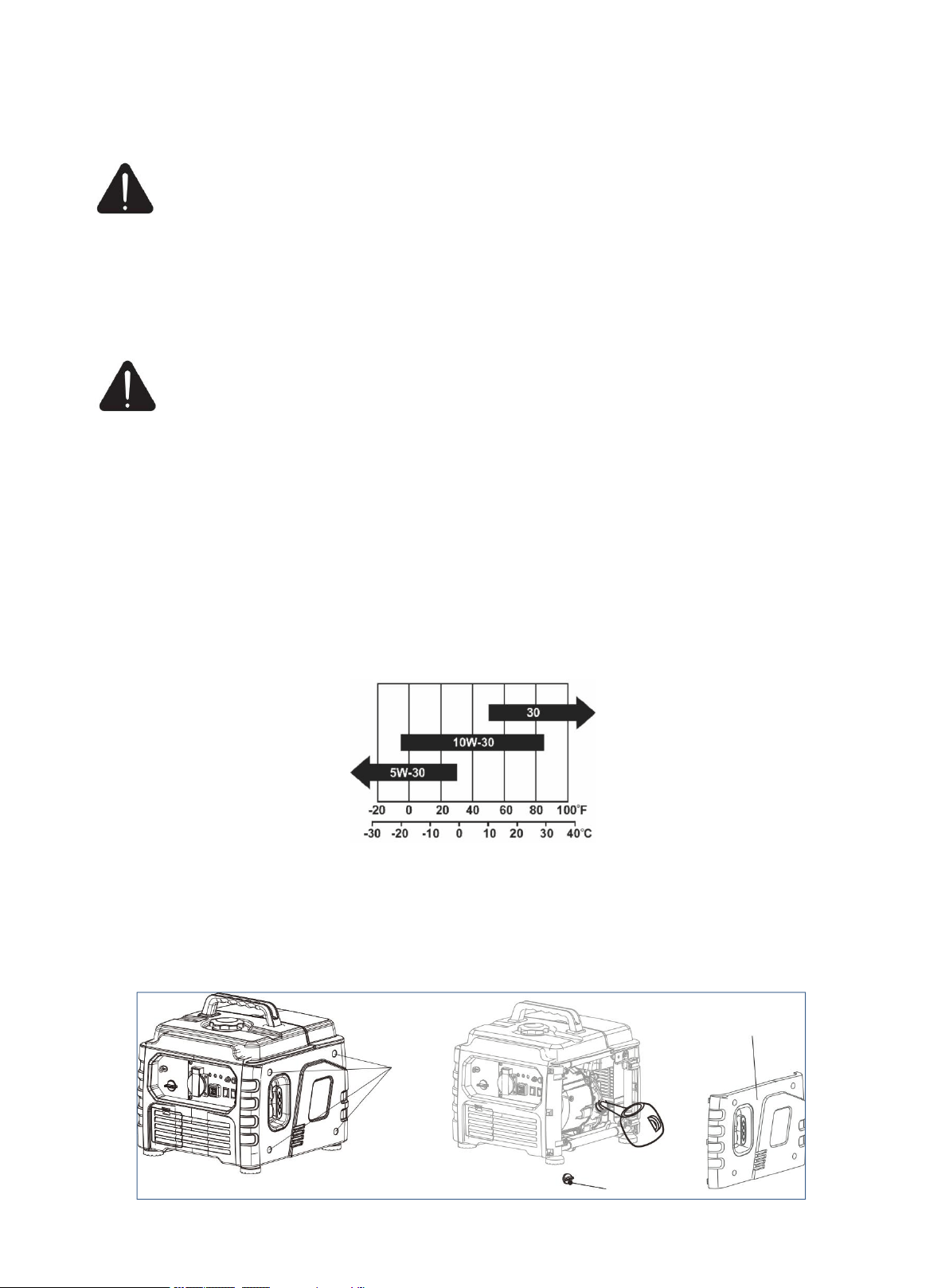
ENGINE OIL RECOMMENDATIONS
Only use 4-stroke engine oil of SJ,SL or equivalent level which are in accordance with or higher than API
standard.
Check the API label on oil bottle or other container, and make sure the “SJ,SL” or equivalent level letter is
in the label.
SAE 10W-30 is recommended for general, all-temperature use. Other viscosities shown in the chart may
be used when the average temperature in your area is within the indicated range.
Ambient Temperature
Place the engine on a level surface with engine stopped. Check the engine oil level. Remove four screws.
Remove the maintenance cover, then remove the filler cap.
Screws
Cover
Filler cap
13
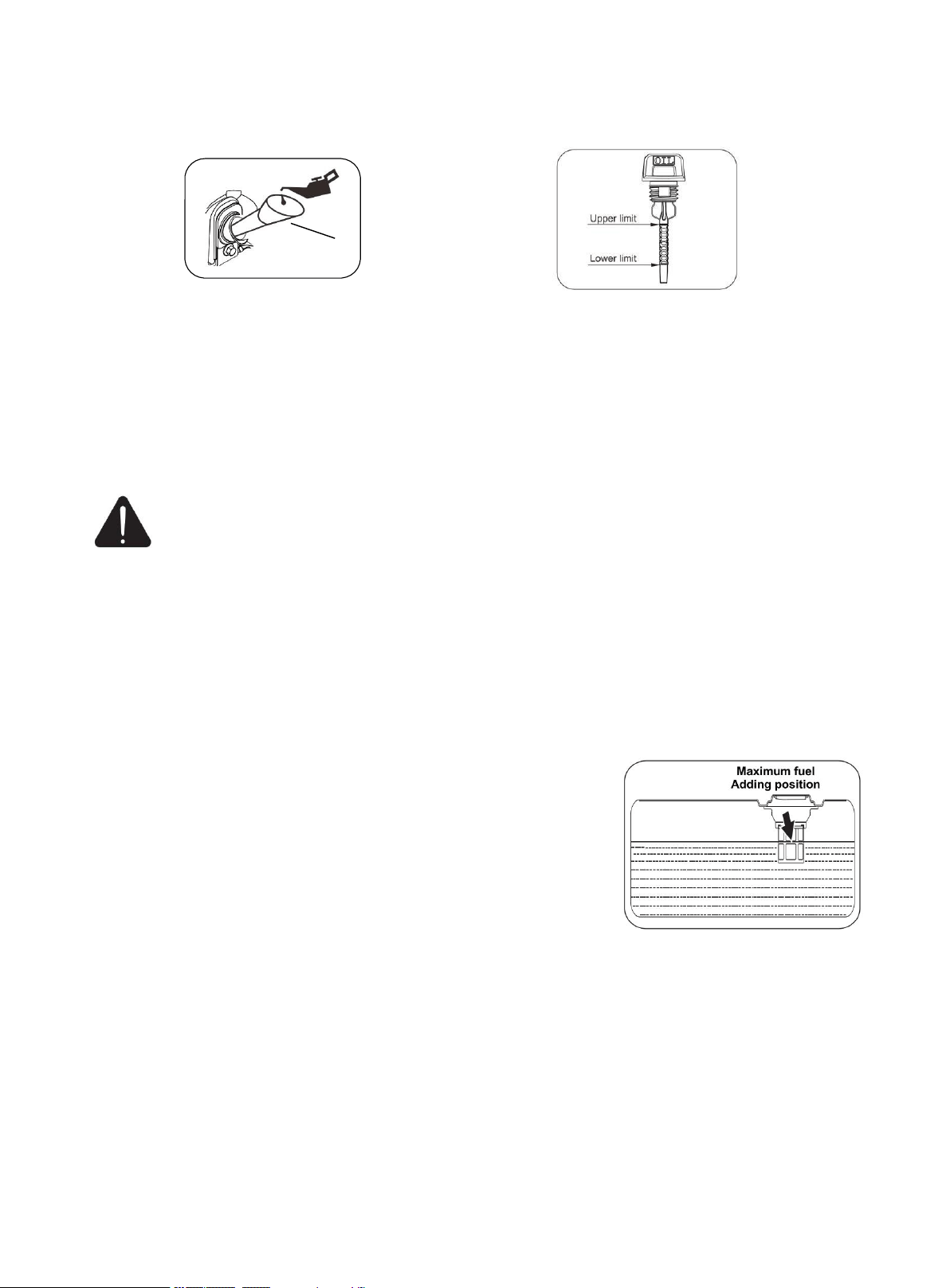
Install dipstick into hole, rest on oil fill neck, DO NOT thread cap into hole. Fill the specified amount
of the recommended engine oil, and then install and tighten the oil filler cap.
Install the cover and tighten the screws.
CAUTION: Operate generator only on a level surfaces. The engine is equipped with a low oil sensor
(applicable types) that will automatic stop the engine when the oil level falls below the safe limit. To
avoid the inconvenient of an unexpected shutdown, fill to the upper limit and check the oil level
regularly.
5. Generating set fuel check
WARNING: This generator may emit highly flammable and explosive gasoline vapors,
which can cause severe burns or even death if ignited. A nearby open flame can lead to
explosion even if not directly in contact with gasoline.
With the engine stopped, check the fuel level. Refill the fuel tank if necessary. Use clean, fresh, regular
unleaded gasoline with a minimum octane rating of 87. Do not mix oil with gasoline. Always wipe up any
spilled fuel.
To add gasoline, follow these steps:
1. Make sure the generator stopped and it is on a level surface.
2. Unscrew fuel cap and set aside.
NOTE: The fuel cap may be tight and hard to unscrew.
3. Slowly add unleaded gasoline to the fuel tank. Be sure not to fill
above the upper limit mark. Always allow room for fuel expansion.
4. The capacity of the fuel tank is 2.8L.
NOTE: Do not fill the fuel tank to the very top. Gasoline will
expand and spill over during use even with the fuel cap in place.
Reinstall fuel cap and wipe clean any spilled gasoline with a dry cloth.
IMPORTANT:
Do not fill tank indoors.
Do not fill tank when the engine is running or hot.
Never use an oil/gasoline mixture.
Never use old gasoline.
Avoid getting dirt or water into the fuel tank.
Gasoline can age in the tank and make starting difficult. Never store generator for extended periods
of time with fuel in the tank or the carburetor.
Turn the fuel cock off and drain the fuel from the carburetor.
Dipstick

14
CATION:
Never use engine or carburetor cleaner products in the fuel tank or permanent damage may occur.
It is important to prevent gum deposits from forming in essential fuel system parts, such as the
carburetor, fuel filter, fuel hose or tank during storage. Also, experience indicates that
alcohol-blended fuels (called gasohol, ethanol or methanol) can attract moisture, which leads to
separation and formation of acids during storage.
Acidic fuel can damage the fuel system of the generating set while in storage. Be sure to review the
instruction given in “Storage” section.
Gasoline/ Alcohol Blends: up to 10% alcohol, 90% unleaded gasoline by volume is approved as a
fuel. Other gasoline/alcohol blends are not approved.
Effects of old, stale or contaminated fuel are not warrantable.
Allow the generating set to cool for at least two minutes before removing fuel cap when adding fuel.
Loose the fuel cap slowly to relieve any pressure in the tank.
6.Generating set grounding
DANGER: Failure to properly ground the generator can result in electrocution.
The generator must be properly connected to an appropriate ground. It helps prevent electrical
shock if a ground fault condition exists in the generating set or in connected electrical devices, especially
when the unit is equipped with a wheel kit. Proper grounding also helps dissipate static electricity,
which often builds up in ungrounded devices.
A ground terminal has been provided on the generating set. For remote grounding, connect of a length of
heavy gauge(4mm
2
) copper wire between the generating set ground terminal and a copper rod driven into
the ground.
Local electrical codes may also require proper grounding of the unit. We strongly recommend that you
consult with a qualified electrician for grounding requirements in your area.
ELECTRICAL DEVICES
Disconnect all electrical devices from the generator and switch off the AC circuit breaker before start the
engine.
The generator may be hard to start with electrical devices.
The connected electrical equipment must not exceed the maximum limit of the generator. Please refer to
the specification table for details.
NOTE: After completing the above preparation, the generator is ready to be started.
15
STARTING THE GENERATOR
CAUTION: Disconnect all electrical loads from the generator before attempting to start.
Pull the starter handle 6-8 times to prefill fuel system before initial operation or removal from long term
storage. Failure to do so could result in bad starting experience.
1. Perform generator preparation (see page. 11) and remove all loads.
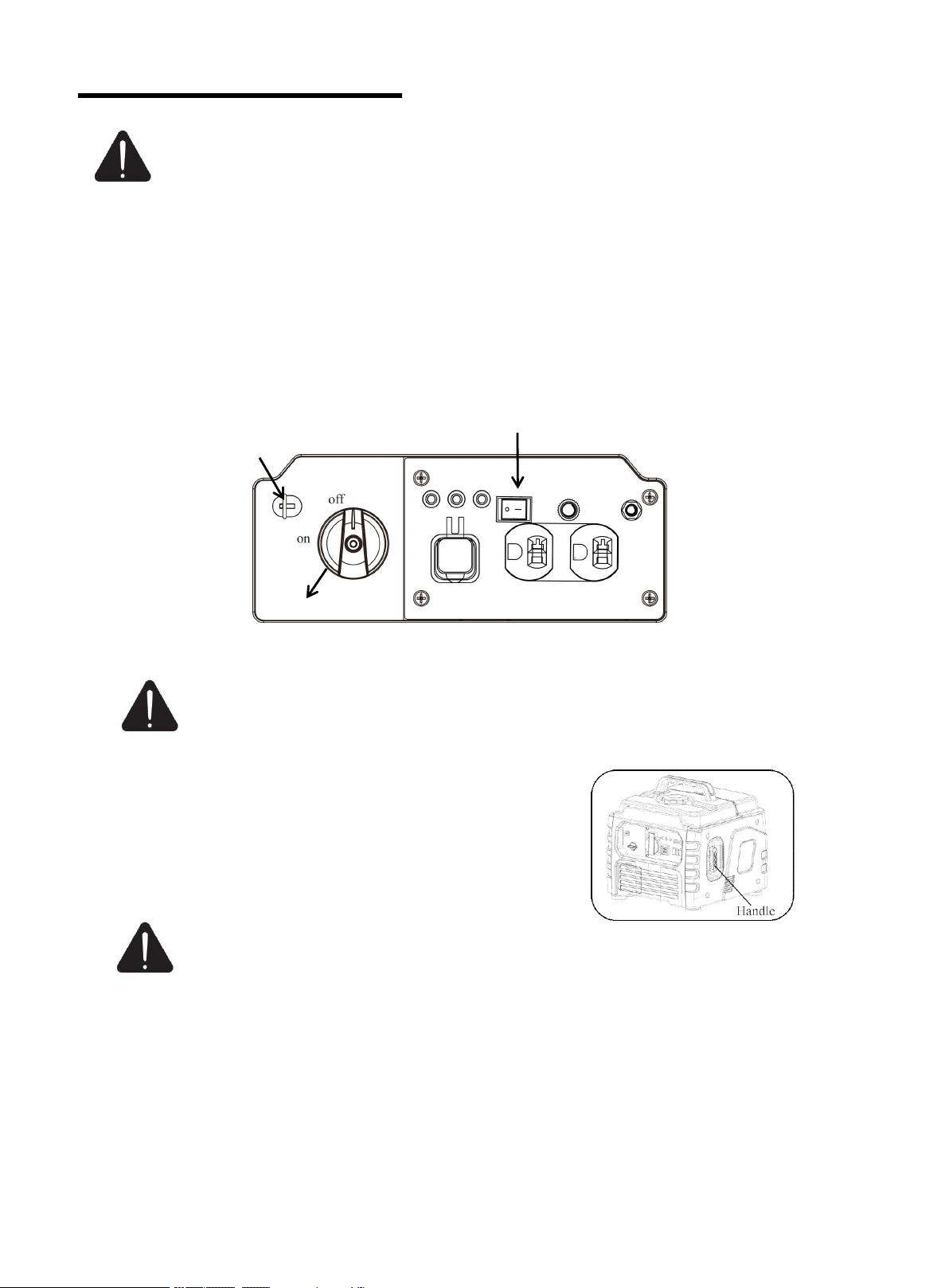
2. Cold start
Turn the engine switch to “ON”.
Pull the chock out.
Turn the fuel switch knob to “ON”
3. Manual start
WARNING: Check starter cord conditions before operating. Have it replaced
immediately by local authorized dealer if cord is frayed.
When starting engine, grasp the recoil starter handle and pull slowly
until resistance is felt. Then pull rapidly to avoid kickback. When
pulling the recoil starter, firmly grasp the carrying handle to avoid
tumble of generating set.
WARNING: KICKBACK
Rapid retraction of the starter cord will pull hand and arm towards the engine faster than you can let go.
Unintentional startup can result in entanglement, traumatic amputation or laceration. Broken bones,
fractures, bruises or sprains could result.
Engine Switch
Chock
Fuel Switch Knob
16
USING THE GENERATOR
WARNING: It is prohibited to start or close the generating set when the output terminal of
generating set is connected to an electric device is in “ON” state.
CONNECT TO ELECTRICAL DEVICES
1. Inspect power cord for damage before using. There is a hazard of electrical shock from crushing,
cutting or heat damage.
2. Make sure that the generating set has been properly grounded. If the electric devices require
grounding, the generating set must ground.
3. Make sure that the electric devices are in “OFF” position.
4. Allow the engine to stabilize and warm up for a few minutes after starting.
5. Connect and start the electric devices.
6. Turn off all electric devices and disconnect them from the generating set.
7. If the generating set supplies for several loads or electric devices, start the smallest one first and the
largest one last.
DANGER: If connected devices overheat, turn them off and disconnect them from
generating set.
Electrical Shock
To reduce the risk of electrical shock, DO NOT use electrical cords that are worn, frayed, bare or
otherwise damaged. DO NOT touch bare wires or receptacles. DO NOT handle generating set or
electrical cords while standing in water, while barefoot, or while hands or feet are wet.
LOADING CAPACITY
WARNING: Do not overload the generating set.
Exceeding the generating set’s capacity can
damage the generating set and/or electric devices connected
to it.
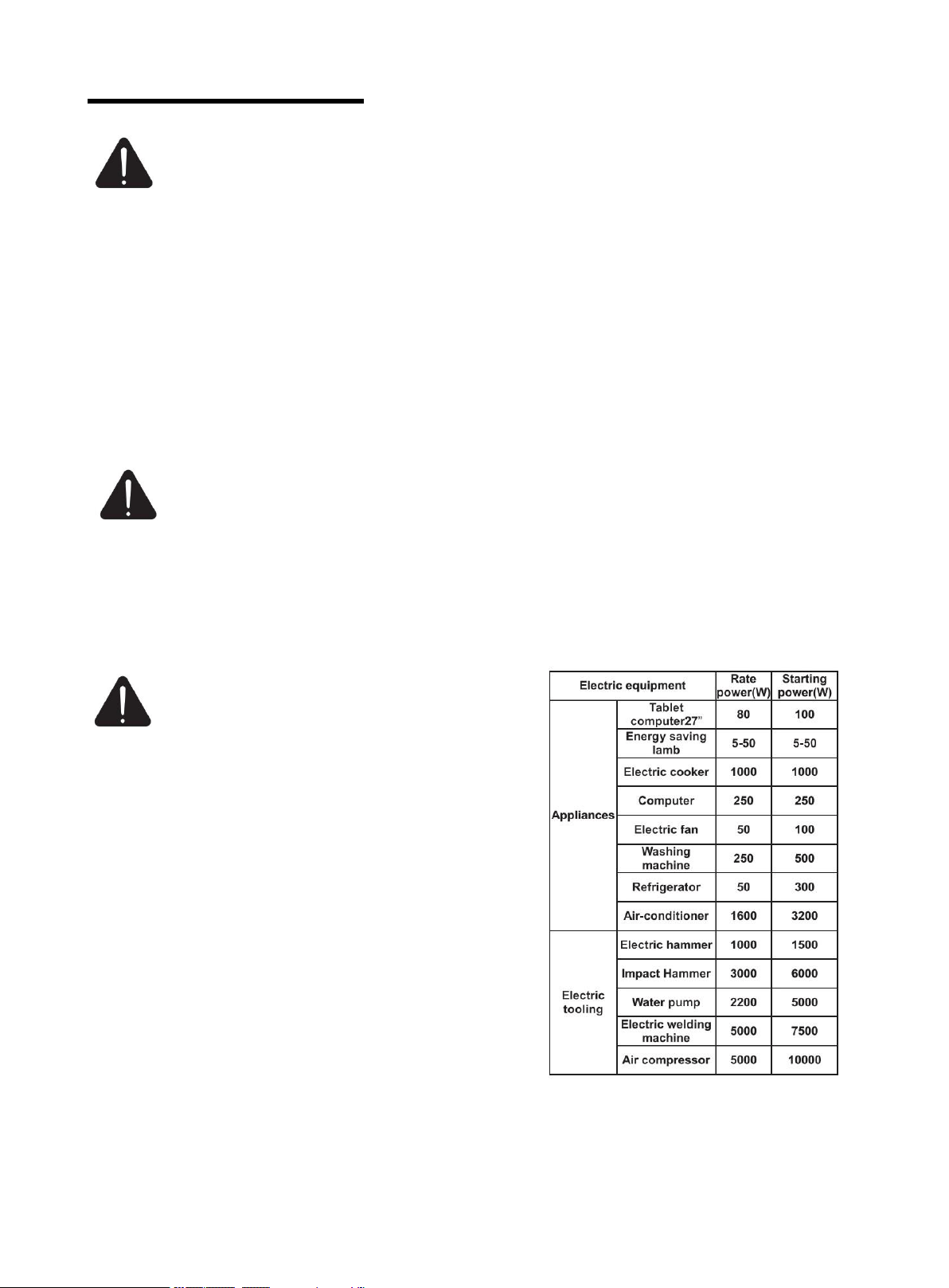
You must make sure your generating set can supply enough
rated (running) and (starting) watts for the electrical devices
at the same time. Follow these simple steps to calculate the
running and starting watts necessary for your purposes.
1. Count the electrical devices you will power at the same
time.
2. The amount of power you need to run with the devices is
the total rated (running) watts of these items.
3. Starting power is the power needed shortly when electric
devices start. Since not all devices start at the same time,
starting power can be estimated by the maximum power of
all devices plus the total power counted in step 2.
Wattage Reference Chart
17
WARNING: It is necessary to equip with circuit protector or switch to isolate the generating set
from the electric utility when the generating set is mainly used for backup. Failure to isolate the
generating set from the power utility may result in injury or death to electric utility workers and damage to
the generating set due to back feed of electrical energy.
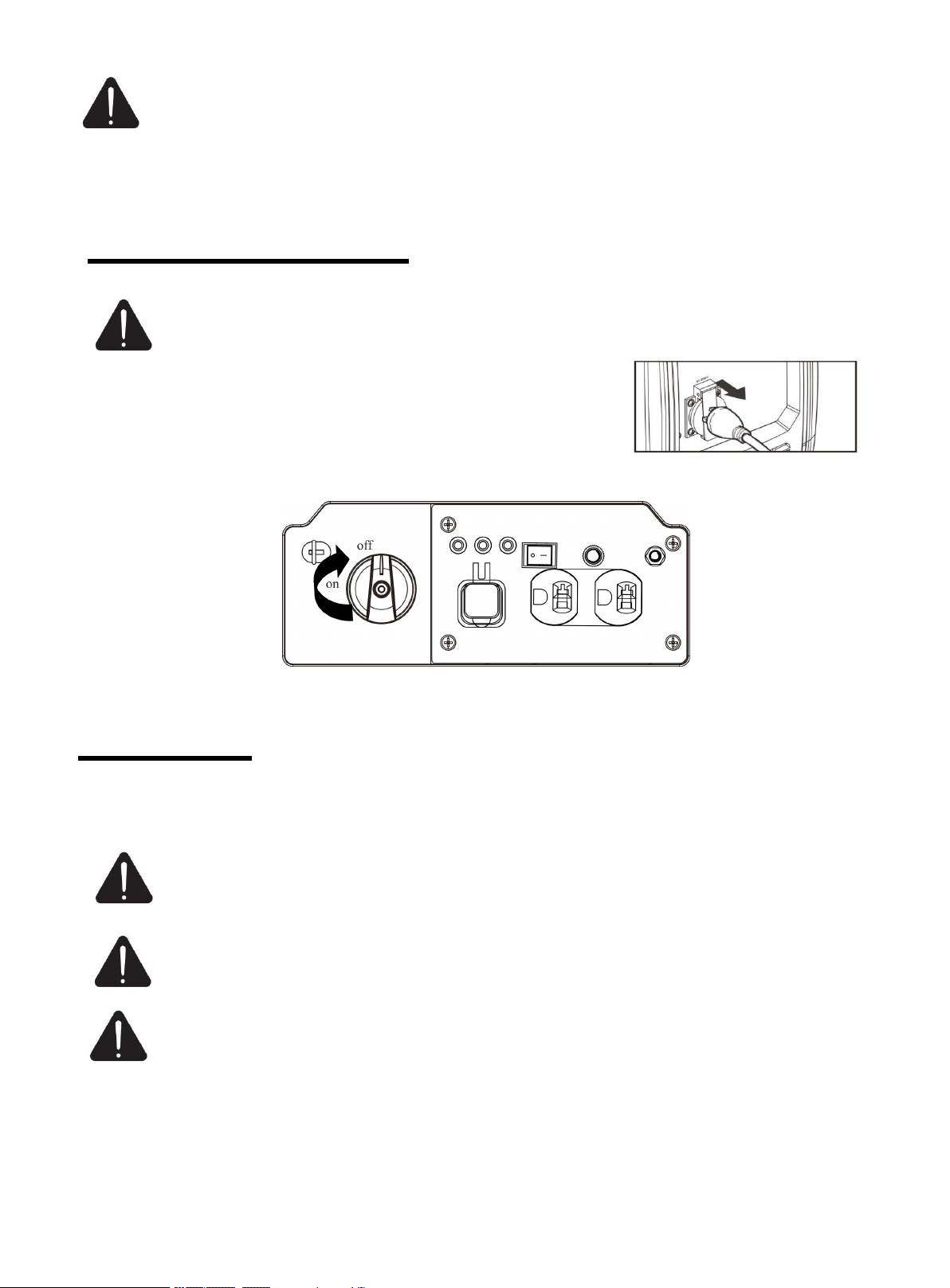
STOPPING THE GENERATOR
WARNING:Never stop the engine with electrical devices connected and with the connected
devices turn “ON”.
1. Remove the connectors of all electric equipment from the generating
set panel.
2. Turn the Fuel switch to “OFF” position, the generator stops operation.
MAINTENANCE
It is the operator’s responsibility to complete all scheduled maintenance in a timely manner. Correct any
issue before operating the generating set. Always follow the inspection and maintenance
recommendations and schedules in this manual.
WARNING: Improper maintenance or failure correct a problem before operation can cause a
malfunction and result in property damage, serious injury or DEATH. Improper maintenance
will void your warranty.
DANGER: Accidental starts can cause severe injury or death. Remove the spark plug cap and
ground generating set before performing any service.
WARNING: The filter element may contains PAHs, PAHs are harmful for your health. Please
wear gloves for protection during air filter maintenance.
18
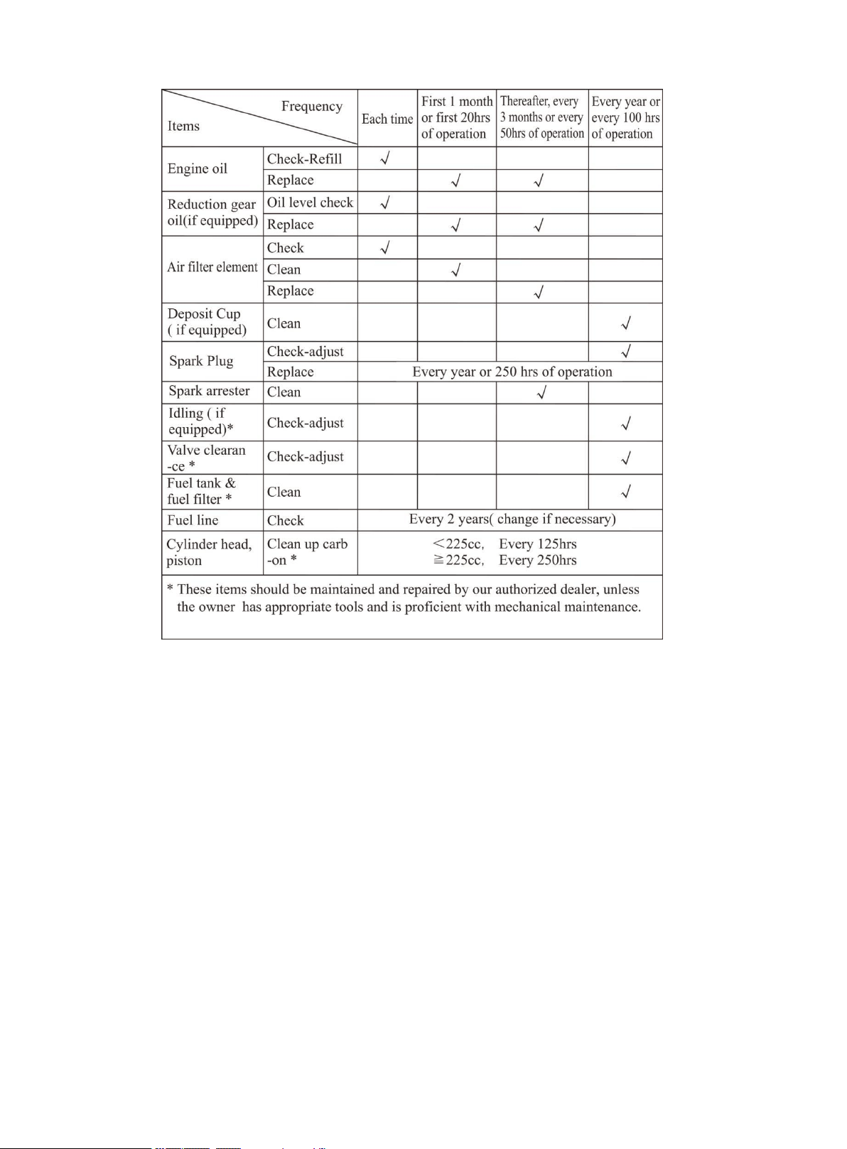
MAINTENANCE SCHEDULE
Stop the generating set before serving, disconnect all electric devices and battery (If equipped),and cool
down the generating set completely.
Serve the generating set in a clean, dry and flat area, so that no accident would happen during the serving.
Please make the wheel in brake state to stop accidental movement of generating set.
Follow the service intervals indicated in the chart below. Service your generating set more frequently
when operating in adverse conditions.
Contact your local authorized service dealer for your generating set or engine maintenance needs.
NOTICE
If the gasoline engine frequently works under high temperature or heavy load, change the oil every 25
hours.
If the engine frequently work under dusty or other severe circumstances, clean the air filter element
every 10 hours; If necessary, change the air filter element every 25 hours.
If maintenance period and the exact time(hour), the one which comes first should govern.
If you have missed the scheduled time to maintain your engine, do it as soon as possible.
19
GENERATING SET MAINTENANCE
WARNING: Never clean the generator when it is running! Never use water to clean the
generating set. Water can enter the generating set through the cooling slots and damage the
generating set windings.
WARNING: Do not modify the generator in any way. Do not tamper with governed speed.
Generator supplies correct rated frequency and voltage when running at factory set. Tampering
with the factory set governor will void your warranty.
Make certain that the generator is kept clean and stored properly.
Use a damp cloth to clean exterior surfaces of the generating set. Use a soft brush to clean the dirt and
oil.
Use an air compressor (25 PSI) to clear dirt and debris from the generating set.
Inspect all air vents and cooling slots to ensure that they are clean and unobstructed.
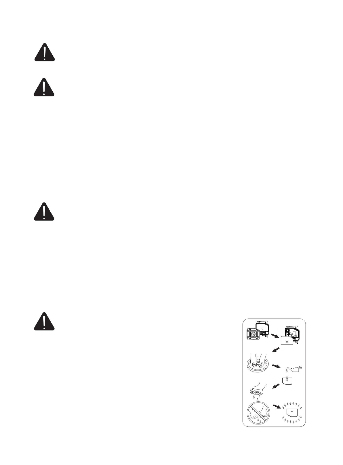
ENGINE MAINTENANCE
Changing the oil
WARNING: Change the oil when the engine is warm form operation. The oil can reach up to
140
℃
under that condition. Careful operation should be taken to prevent burns.
1. Place the machine on a level surface which is 300mm higher than the ground.
2. Remove the right cover.
3. Place the waste oil box on the ground.
4. Remove the oil dipstick, and tilt the machine to pour the oil.
5. Add recommended oil to the upper limit.
6. Fully tighten the dipstick.
7. Properly dispose of any used oil at an approved waste management facility.
8. Reinstall the oil maintenance cover.
AIR FILTER
WARNING: Do not run the engine without the air filter, or
serious danger can result.
Routine maintenance of the air cleaner helps maintain proper
airflow to the carburetor. Occasionally check that the air cleaner is free of
excessive dirt.
1. Remove the air filter maintenance cover.
2. Loose the filter fix clamp and remove the cover of the air filter.
3. Remove the foam filter element.
4. Wash in liquid detergent and warm water.
5. Squeeze thoroughly dry in a clean cloth.
6
. Saturate in clean engine oil.
7. Squeeze in a clean , absorbent cloth to remove all excess oil.
8. Assemble the filter element onto the filter unit.
9. Assemble the filter fix clamp.
10. Reinstall the air filter maintenance cover.
20
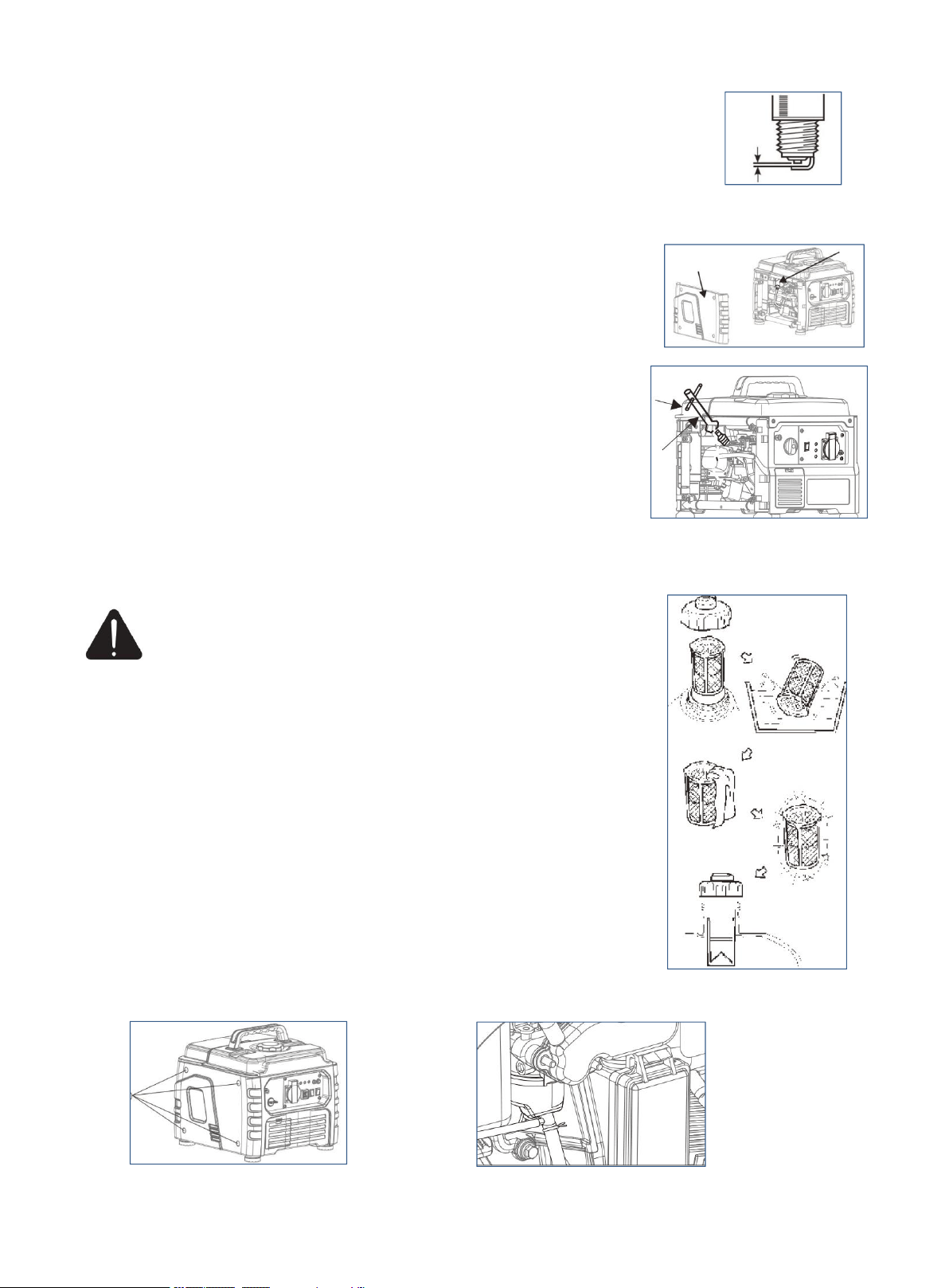
SPARK PLUG
Spark plug gap : 0.6mm-0.8mm(0.024-0.031 in). Spark plug tighten torque:
12.5N.m
The spark plug is important for proper engine operation. A good spark plug should be intact, free of
deposits, and properly gapped. Refer to Recommended Maintenance Schedule. To inspect the spark plug:
1. Clean any dirt from the spark plug cap and spark plug base.
2. Remove the cap (a) and the spark plug cap (b), Insert the tool through the
hole from the outside of the cover.
3. Insert the handlebar (c) into the tool (d) and turn it counterclockwise to
remove the spark plug.
4. Check for discoloration and remove the carbon. The porcelain insulator
around the center electrode of spark plug should be a medium-to-light tan
color.
CAUTION: Only use recommended spark plug or equivalent. Do not use spark plugs that have
improper heat range.
FUEL TANK FILTER
WARNING: Never use the gasoline while smoking or in the
vicinity of an open flame.
1. Remove the fuel tank cap and filter.
2. Clean the filter with gasoline.
3. Wipe the filter and install it.
4. Install the fuel tank cap.
Be sure the fuel tank cap is tightened securely.
FUEL FILTER
1.Remove the screws, take the cover down and drain the fuel.
2. Hold and move up the clamp, take off the hose from the tank.
3.Take out the fuel filter.
4. Clean the filter with gasoline.
5.Dry the filter and put it back into tank.
6.Install the hose and clamp, then open the fuel valve to check whether it is leak.
7. Install the cover and tighten the screws.
a
Screws
b
c
d

21
STORAGE & TRANSPORT PROCEDURES
STORAGE
WARNING: Gasoline is highly flammable and extremely explosive. Empty the fuel tank
and shut off fuel valve before storing or transporting this generating set.
The generating set should be started at least once every 2 weeks and allowed to run for at
least 20 minutes. Follow the instructions below for longer term storage if the generating set will be
out of service for 2 months or more.
Allow the generating set to cool completely before storage.
Clean the generating set according to instruction in maintenance section.
Drain all fuel completely from the fuel tank, fuel hose and carburetor to prevent gum from forming.
Turn off the fuel supply at the fuel valve.
Change the oil.
Reattach the spark plug.
Remove the spark plug and pour about 15ml of oil into the cylinder.Crank the engine slowly
to distribute the oil and lubricate the cylinder.
Store the unit in a clean, dry area out of direct sunlight.
TRANSPORT
To prevent fuel spillage when transporting or during temporary storage, the generating set should be
secured upright in its normal operating position, with the engine switch OFF. The combination switch
should be in the “stop” position and knob of the fuel cap should be turned to the “OFF” position.
When transporting:
Do not overfill the tank.
Do not operate the generating set while it is on vehicle. Take the generating set off the vehicle and
use it in a well-ventilated place. Avoid a place exposed to direct sunlight when putting the generating set
on a vehicle. If the generating set is left in an enclosed vehicle for many hours, high temperature inside
the vehicle could cause fuel to vaporize resulting in a possible explosion.
Do not drive on a rough road for an extended period with the generating set on a rough road, drain the
fuel from the generating set beforehand.
22
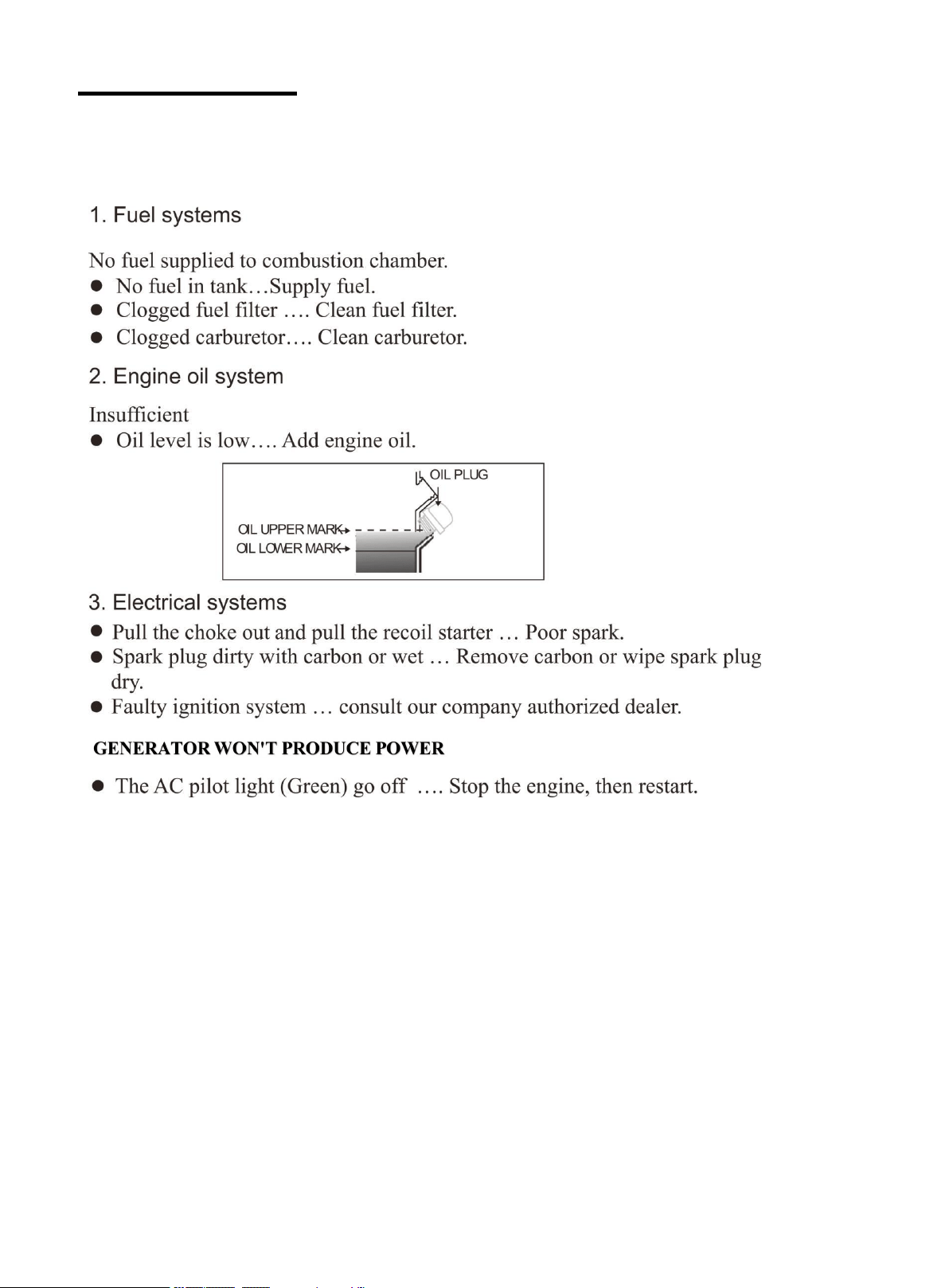
TROUBLESHOOTING
ENGINE WON’T START
23
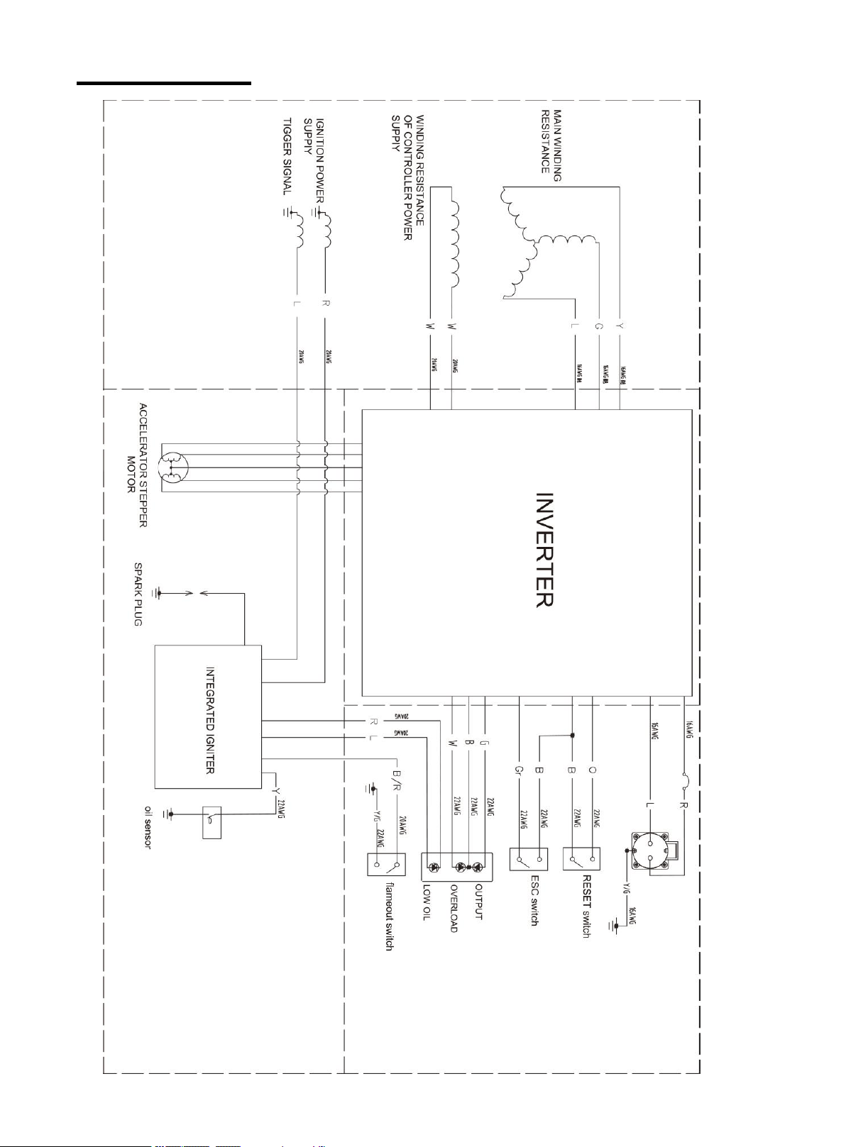
WIRING DIAGRAM
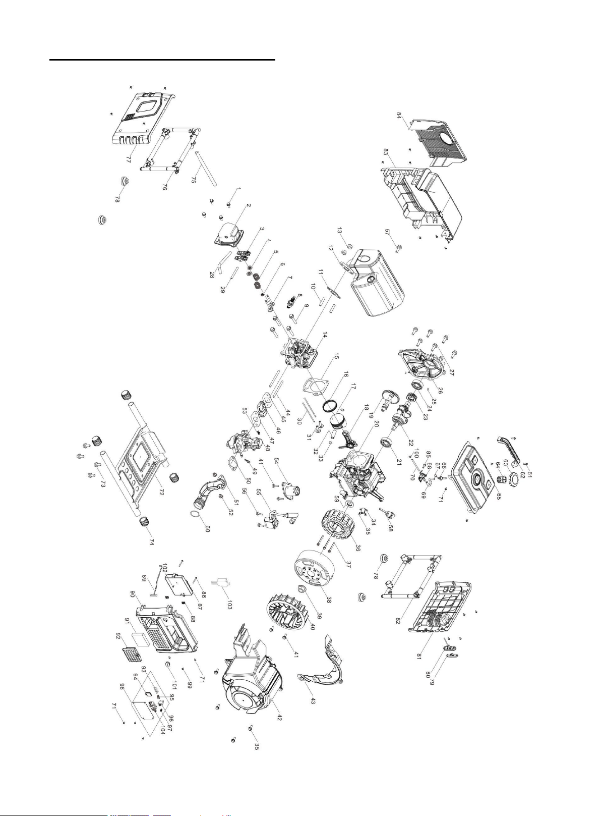
24
EXPLODED VIEW & PARTS LIST

25
Generator parts list
Item
Stock#
Description
Qty
1
PS55-001
BOLT
4
2
PS55-002
COVER SUBASSEMBLY, CYLINDER HEAD
1
3
PS55-003
ROCKER SUBASSEMBLY, VALVE
2
4
PS55-004
SEAT, VALVE SPRING
2
5
PS55-005
SPRING, VALVE
2
6
PS55-006
GUIDE, SEAL
1
7
PS55-007
VALVES SET
1
8
PS55-008
PLUG, SPARK
1
9
PS55-009
BOLT
4
10
PS55-010
STUD BOLT
2
11
PS55-011
GASKET, EXHAUST OUTLET
1
12
PS55-012
MUFFLER ASSY.
1
13
PS55-013
HEXAGON NUT
2
14
PS55-014
HEAD SUBASSEMBLY, CYLINDER
1
15
PS55-015
GASKET, CYLINDER HEAD
1
16
PS55-016
RING ASSY, PISTON
1
17
PS55-017
PISTON
1
18
PS55-018
ROD, CONNECTING
1
19
PS55-019
CAMSHAFT ASSY.
1
20
PS55-020
CRANKCASE SUBASSEMBLY.
1
21
PS55-021
DEEP GROOVE BALL BEARING
1
22
PS55-022
CRANKSHAFT ASSY.
1
23
PS55-023
GEAR, TIMING DRIVE
1
24
PS55-024
DEEP GROOVE BALL BEARING
1
25
PS55-025
POSITION PIN - TYPE A
2
26
PS55-026
COVER, CRANKCASE
1
27
PS55-027
BOLT
6
28
PS55-028
TUBE, BREATHER
1
29
PS55-029
SHAFT, VALVE ROCKER
1
30
PS55-030
LIFTER SUBASSEMBLY, VALVE
2
31
PS55-031
TAPPET, VALVE
2
32
PS55-032
PIN, PISTON
1
33
PS55-033
CLIP, PISTON PIN
2
34
PS55-034
TRIGGER ASSY.
1
35
PS55-035
BOLT
6
36
PS55-036
STATOR SUBASSEMBLY, MAGNETO
1
37
PS55-037
HEXAGON SOCKET FLANGE FACE BOLT -
SMALL SERIES
3
38
PS55-038
CASE SUBASSEMBLY, MAGNETO ROTOR
1
39
PS55-039
HEXAGON NUT WITH FLANGE
1
40
PS55-040
IMPELLER
1
41
PS55-041
BOLT
4
42
PS55-042
MANUAL STARTING ASSEMBLY
1
43
PS55-043
SHIELD, CRANKCASE REAR
1
44
PS55-044
STUD BOLT (BM=2D)
2
45
PS55-045
GASKET, CARBURETOR INSULATOR
1
46
PS55-046
PLATE, CARBURETOR INSULATOR
1
47
PS55-047
CARBURETOR SEAL GASKET
1

26
48
PS55-048
CARBURETOR ASSY.
1
49
PS55-049
STRAINER
,
FUEL
1
50
PS55-050
AIR CLEANER SEAL GASKET
1
51
PS55-051
AIR CLEANER INTAKE DUCT ASSEMBLY
1
52
PS55-052
HEXAGON NUT WITH FLANGE
2
53
PS55-053
CLIP, GOVERNOR ROD
1
54
PS55-054
SENSOR, ENGINE OIL
1
55
PS55-055
COIL, IGNITION
1
56
PS55-056
BOLT
2
57
PS55-057
BOLT
1
58
PS55-058
DIPSTICK SUBASSEMBLY, OIL
1
59
PS55-059
SEAL, OIL
1
60
PS55-060
CLIP
1
61
PS55-061
CROSS-RECESSED PAN HEAD SCREW
2
62
PS55-062
HANDLE
1
63
PS55-063
COVER, FUEL TANK
1
64
PS55-064
STRAINER
,
FUEL
1
65
PS55-065
FUEL TANK
1
66
PS55-066
OUTLET SUBASSEMBLY, FUEL TANK OIL
1
67
PS55-067
COLLAR
1
68
PS55-068
COCK ASSY, FUEL
1
69
PS55-069
TUBE, FUEL
1
70
PS55-070
TUBE, FUEL
1
71
PS55-071
SELF-TAPPING SCREW
26
72
PS55-072
ENGINE FIXED BOTTOM PLATE
1
73
PS55-073
BOLT
4
74
PS55-074
BUFFERING PAD SUPPORT
4
75
PS55-075
PIPE, ENGINE FRAME CONNECTING
1
76
PS55-076
FRAME ASSY, ENGINE
1
77
PS55-077
LEFT HOUSING COVER PLATE
1
78
PS55-078
SEAT, ENGINE FRAME SHOCK ABSORPTION
4
79
PS55-079
CORE, CABLE HANDLE
1
80
PS55-080
SLEEVE, CABLE HANDLE OUTER
1
81
PS55-081
RIGHT APPEARANCE COVER PLATE
1
82
PS55-082
FRAME ASSY, ENGINE
1
83
PS55-083
COVER, MUFFLER SIDE
1
84
PS55-084
COVER, MUFFLER SIDE
1
85
PS55-085
BOLT
1
86
PS55-086
HEXAGON SOCKET FLANGE FACE BOLT -
SMALL SERIES
2
87
PS55-087
INVERTOR
1
88
PS55-088
CLIP NUT
2
89
PS55-089
CHOKE PULL ROD
1
90
PS55-090
SEAT, PANEL
1
91
PS55-091
ELEMENT, AIR CLEANER
1
92
PS55-092
COVER, AIR CLEANER CASE
1
93
PS55-093
STATUS DISPLAY BOARD ASSEMBLY
1
94
PS55-094
SOCKET SUBASSEMBLY, D.C
1
95
PS55-095
SWITCH SUBASSEMBLY
1
96
PS55-096
BUTTON, RESETTING
1
97
PS55-097
TERMINAL SUBASSEMBLY, GROUNDING
1
98
PS55-098
PANEL SUBASSEMBLY, CONTROL
1

27
99
PS55-099
BOLT
1
100
PS55-100
COLLAR
3
101
PS55-101
PLUG, END
1
102
PS55-102
CROSS-RECESSED PAN HEAD SCREW
1
103
PS55-103
REGULATOR, VOLTAGE
1
104
PS55-104
SOCKET SUBASSEMBLY, POWER SUPPLY
1

28
THREE (3) YEARS LIMITED WARRANTY
PowerSmart
®
is committed to building tools that are dependable for years. Our warranties are consistent with our
commitment and dedication to quality.
THREE (3) YEARS LIMITED WARRANTY OF POWERSMART PRODUCTS FOR HOME USE.
PowerSmart (“Seller") warrants to the original purchaser only, that all PowerSmart consumer power tools will be free
from defects in material or workmanship for a period of three (3) years from date of purchase. Ninety (90) days for all
PowerSmart Products, if the tool is used for professional or commercial use.
SELLER’S SOLE OBLIGATION AND YOUR EXCLUSIVE REMEDY under this Three (3) Years Limited
Warranty and, to the extent permitted by law, any warranty or condition implied by law, shall be the repair or
replacement of parts, without charge, which are defective in material or workmanship and which have not been
misused, carelessly handled, or misrepaired by persons other than Seller or Authorized Service Center. To make a
claim under this Limited Warranty, you must return the entire power tool product; transportation prepaid, to
PowerSmart Include a legible copy of the original receipt, which lists the date of purchase (month and year) and the
name of the company purchased from.
THIS LIMITED WARRANTY DOES NOT APPLY TO ANY ACCESSORY ITEMS INCLUDED WITH THE
TOOL SUCH AS CIRCULAR SAW BLADES OTHER RELATED ITEMS OR TO ANY REPLACEMENT PARTS
LISTED UNDER MAINTENANCE.
ANY IMPLIED WARRANTIES SHALL BE LIMITED IN DURATION TO THREE (3) YEARS FROM DATE OF
PURCHASE. SOME STATES IN THE U.S. AND SOME CANADIAN PROVINCES DO NOT ALLOW
LIMITATIONS ON HOW LONG AN IMPLIED WARRANTY LASTS, SO THE ABOVE LIMITATION MAY
NOT APPLY TO YOU.
IN NO EVENT SHALL SELLER BE LIABLE FOR ANY INCIDENTAL OR CONSEQUENTIAL DAMAGES
(INCLUDING BUT NOT LIMITED TO LIABILITY FOR LOSS OF PROFITS) ARISING FROM THE SALE OR
USE OF THIS PRODUCT. SOME STATES IN THE U.S. AND SOME CANADIAN PROVINCES DO NOT
ALLOW THE EXCLUSION OR LIMITATION OF INCIDENTAL OR CONSEQUENTIAL DAMAGES, SO THE
ABOVE LIMITATION OR EXCLUSION MAY NOT APPLY TO YOU.
THIS LIMITED WARRANTY GIVES YOU SPECIFIC LEGAL RIGHTS, AND YOU MAY ALSO HAVE OTHER
RIGHTS WHICH VARY FROM STATE TO STATE IN THE U.S., PROVINCE TO PROVINCE IN CANADA
AND FROM COUNTRY TO COUNTRY.
For questions / comments, technical assistance or repair parts –
Please call toll free at: 1-800-791-9458 (M-F 9am – 5pm EST)
Email: suppo[email protected]
SAVE YOUR RECEIPTS. THIS WARRANTY IS VOID WITHOUT THEM.