INSTRUCTION MANUAL
EN 21"ELECTRIC SNOW THROWER
FR 21"CHASSE-NEIGE ÉLECTRIQUE
ES LANZDE NIEVE ELECTRICA DE 21"
Model
Have product questions or need technical support? Please feel free to contact us!
Website: www.Amerisuninc.com
www.PowerSmartUSA.com
Toll free: 1-800-791-9458 Mon-Fri 9-5 EST
Email: support@amerisuninc.com
# DB5021

2

3
TABLE OF CONTENTS
Feature Identification ...................................................................................... 4
Safety Information ........................................................................................... 5
Assembly Instructions ..................................................................................... 8
Operating Instructions ..................................................................................... 11
Troubleshooting .............................................................................................. 16
Care and Maintenance ..................................................................................... 17
Exploded View and Part List........................................................................... 18
Two Years Limited Warranty .......................................................................... 22
PRODUCTS SPECIFICATIONS
Voltage:120v,60Hz
Input Power:15Amp
Rotation speed:2,100 RPM
Clearing width and depth: Approx. 53 cm x 27 cm (21 in. x 11 in.)
Max. throwing distance: 10 m (30 ft.)
Net Wight:18 kg (40lbs)
EN
4
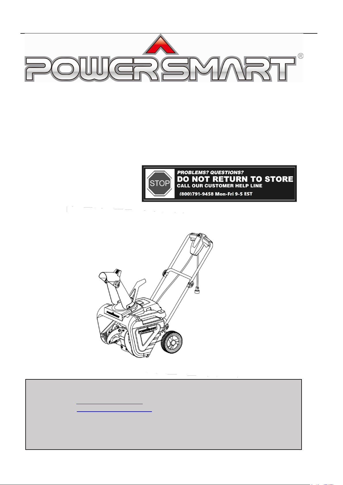
FEATURE IDENTIFICATION
1
Auger Control
7
Auger
2
Switch button
8
Chute Deflector
3
Upper Tube
9
Chute
4
Polarized Plug
10
Chute Crank
5
Lower Tube
11
Knob
6
Wheel
3
4
5
6
1 2
7
8 9 10 11

5
SAFETY INFORMATION
Please read and understand this entire manual before attempting to assemble, operate or install the product.
Work Area
Keep work area clean and well-lit. Cluttered, dark areas invite accidents.
Do not operate snow thrower in an explosive atmosphere, such as in the presence of flammable liquids, gases,
or dust. Electrical appliances create sparks that may ignite the dust or fumes.
Keep children, pets, and bystanders away from work area. Be aware that the normal noise of the machine when
turned on may make it difficult for you to hear approaching people.
Electrical Safety
Electrical plugs must match the outlet. Never modify the plug in any way. Do not use any adaptor plugs with
grounded appliances. Unmodified plugs and matching outlets will reduce risk of electric shock.
Avoid body contact with earthed or grounded surfaces such as pipes, radiators, ranges, and refrigerators. There
is an increased risk of electric shock if your body is earthed or grounded.
Do not abuse the cord. Keep cord away from heat, oil, sharp edges or moving parts. Damaged or yank the cord
to disconnect it from the electrical outlet.
Replace or properly repair damaged cords. If cord is damaged in any manner while plugged in, pull the
extension cord from the wall receptacle.
Contact with water while operating the snow thrower can result in electric shock and serious bodily injury. Do
not use the snow thrower in damp or wet locations or expose to rain. Do not handle the plug or the appliance
with wet hands or while standing in water.
Extension Cord-WARNING –Only use a UL-rated extension cord for OUTDOOR, all-weather use (usually
orange color).The extension cord MUST be of the proper gauge size depending on it’s length(see page 14).To
prevent the extension cord from disconnecting during operation.tie it around top right side of the middle frame
before connecting it to the snow thrower as shown in Figure 2 on page 14.
Turn off the power switch and disconnect the power cable before inspecting, servicing, repairing, or cleaning
the snow thrower stop completely.
Do not move or transport the snow thrower when the plug is connected to the power socket and the switch in
turned on.
Personal Safety
Stay alert-watch what you are doing and use common sense when operating the snow thrower.
Do not use the machine when tired, ill, or under the influence of drugs, alcohol, or medication. A moment of
inattention may result in serious personal injury.
Wear proper clothing-Wearing rubber boots offers additional protection from electric shock. Do not wear loose
clothing or jewelry that may become caught in the machine. Wear protective headgear to keep hair away from
revolving parts of the machine. Safety glasses offer better protection than everyday eyeglasses.
Moving parts present risks –Keep your face, hair, clothing, hands, and feet away from moving parts. All guards
and safety attachments must be installed properly before using the unit. Shut off and disconnect cord before
touching any parts other than handles and switch.
Surfaces-This snow thrower is intended for use on paved surfaces. Do not use on gravel, stone, or other
unpaved surfaces unless the snow thrower is adjusted for such surfaces according to the instructions given in
the operators manual.
Avoid accidental starting –Make sure the switch is in the off position before plugging in the unit. Do not carry
the snow thrower with your finger on the switch.

6
Body position-Maintain proper footing and balance at all times. Place heels firmly on the ground and tightly
grasp the handle bar. Watch for uneven surfaces and do not over reach. In case you fall or collide with the snow
thrower, inspect the unit for damage. When steeping backwards, be careful to avoid obstacles beneath your feet
or behind you to avoid falling.
Snow Thrower Use and Care
Know your snow blower-Familiarize yourself with the main parts of your snow thrower. Read the operators
manual carefully. Learn your snow throwers applications and limitations as well as specific potential hazards
related to this machine. Do not use this machine for any purpose other than one for which it was designed.
Otherwise, it may cause mechanical defaults, serious damage or personal injury.
Preliminary unit inspection –Thoroughly inspect the unit before use. Make sure all the parts are secure and
installed correctly. If you notice any abnormalities, do not use the machine until it has been properly repaired.
Always perform a test run the first time you use the snow thrower or after replacing parts to ensure that unit is
functioning properly.
Preliminary area inspection-Clear the area to be plowed before each use. Remove all objects such as rocks,
broken glass, nails, wire, or string which can be thrown by or become entangled in the snow thrower .Keep the
area of operation clear of other people and pets.
Excessive force –The snow thrower was designed to respond at a certain rate for various snow conditions for
optimum safety band performance. Do not force it; keep pressure constant.
Malfunctioning switch-Do not use the snow blower if the switch does not turn it on and off. Any electrical
appliance that can not be controlled by the switch is not safe to use and must be repaired.
Hitting an object-If the snow thrower accidentally strikes an object, stop the snow thrower. Inspect for damage;
repair or replace any damaged part before restarting and operating the snow thrower.
Discharge chute safety -Never direct the snow discharge chute at the operator, at bystanders, at vehicles or at
windows. Thrown snow and foreign objects accidentally picked up by the snow thrower can cause serious
damage and personal injury. Do not use your hands to unclog the discharge chute. Stop the motor before
removing debris.
Abnormal operation-If you notice the snow thrower running in an unstable state or hear abnormal sounds from
machine,stop the machine, disconnect the power immediately, and contact your original distributor.
Noise control-When using the snow thrower, you must respect local laws and regulations regarding noise
control and environmental protection. To avoid noise disturbance, you should carefully decide upon an
appropriate operation time and consider the surrounding conditions.
When work is completed -Disconnected the snow thrower from the power source when not in use, when
changing accessories, and before performing any maintenance.
Store safety-Store snow thrower indoors in a dry area between uses. Keep in a locked area where children and
unauthorized users can not gain access. Do not store the machine while it is still connected to the power source.
It may cause damage and injury.
Maintain for safety and longevity-Check for misalignment or binding of moving parts, breakage of parts, and
any other conditions that may affect the units operation. If damaged, repair or replace the damaged part before
use. Use only those replacement parts made for your model. When replacing any parts, you must strictly
observe the instructions and procedures described in this manual. Special care should be paid to any rubber
parts, since these parts may increase the engine load and decrease its mechanical power if damaged.
7
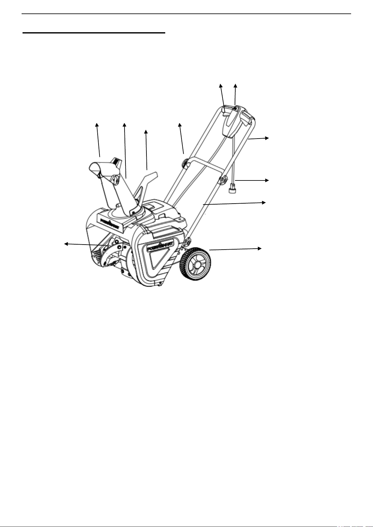
PRODUCT LABELS
WARNING-Read, understand and follow all safety labels and markings on the unit.
CAUTION
Inspect wiring, which, if damaged during shipping, may cause serious bodily injury during equipment use. If any
damage is seen or suspected, do not assemble. instead, contact our customer service department at 1-800-791-9458.
Handle with care during assembly so that electrical wiring does not become damaged.
8
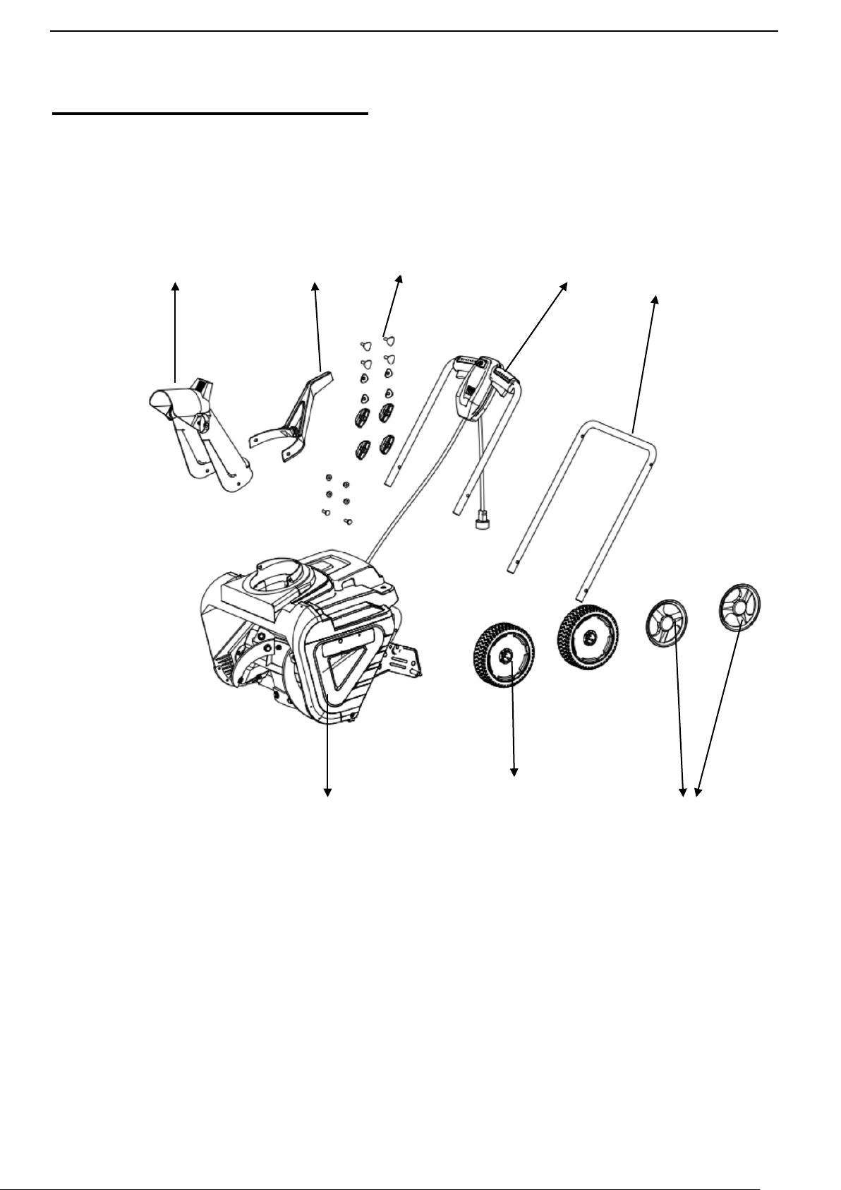
ASSEMBLY INSTRUCTIONS
1 .Remove the machine and accessories from the packing box
Machine wheel wheel cover
Chute Assembly
Chute Crank Standard Component Upper Handle Lower Handle
9
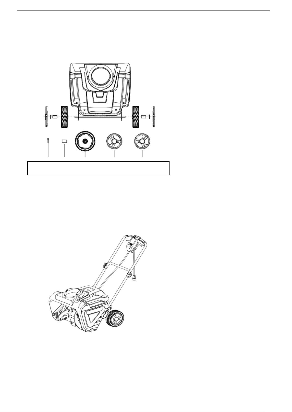
2. Place wheel to the axle shown below and insert the cotter pin into the hole in the axle.
Bend the cotter pin and install the wheel cover.
3. Place upper&lower tube in the position shown below and tighten the knobs.
Cutter pin (2) Spacer (2) wheel (2) wheel cover L wheel cover R
10
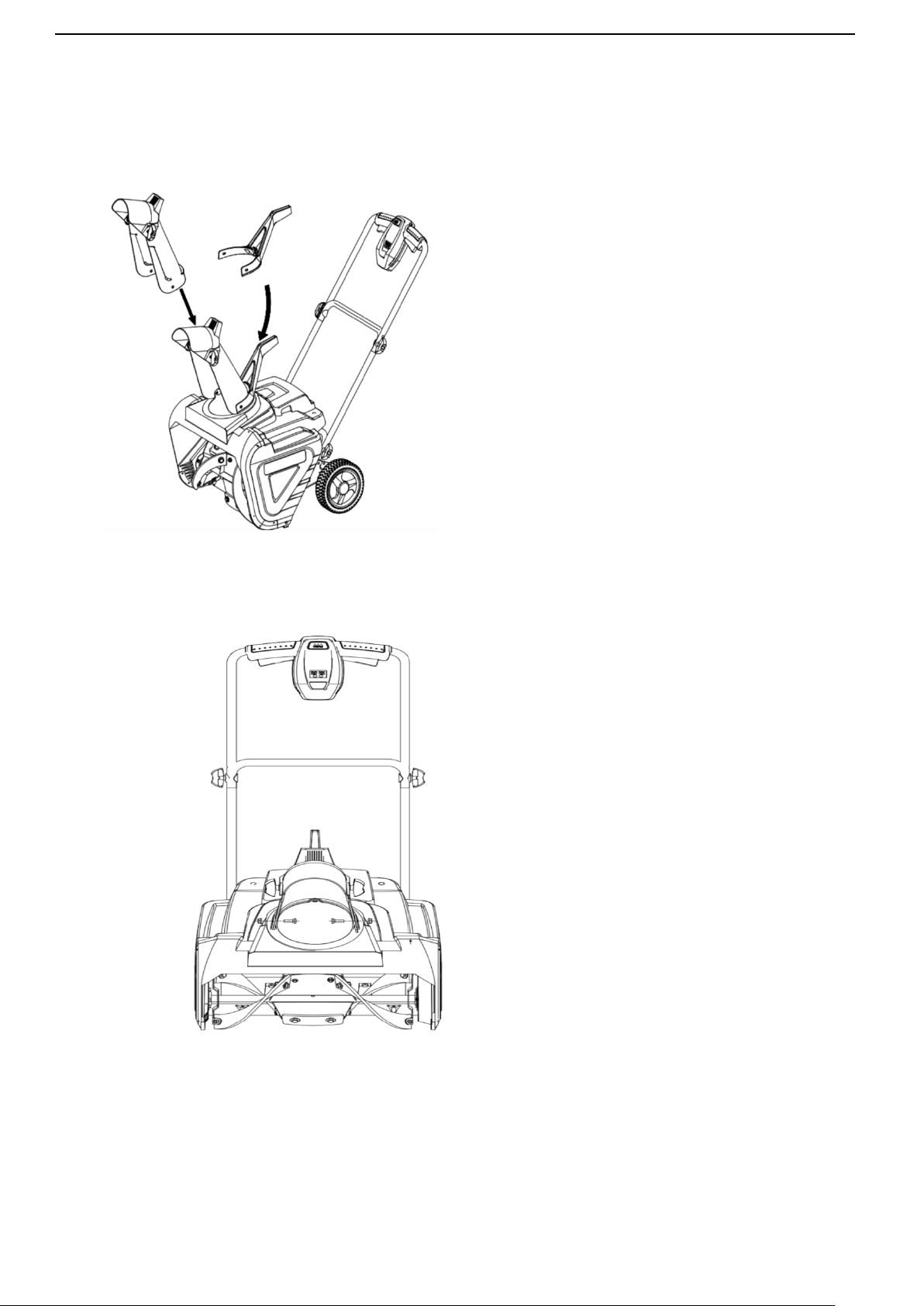
4. Place the Chute assembly on the rotating bracket as shown in below.
5. Use two screws to lock the chute assembly into rotation bracket.
11
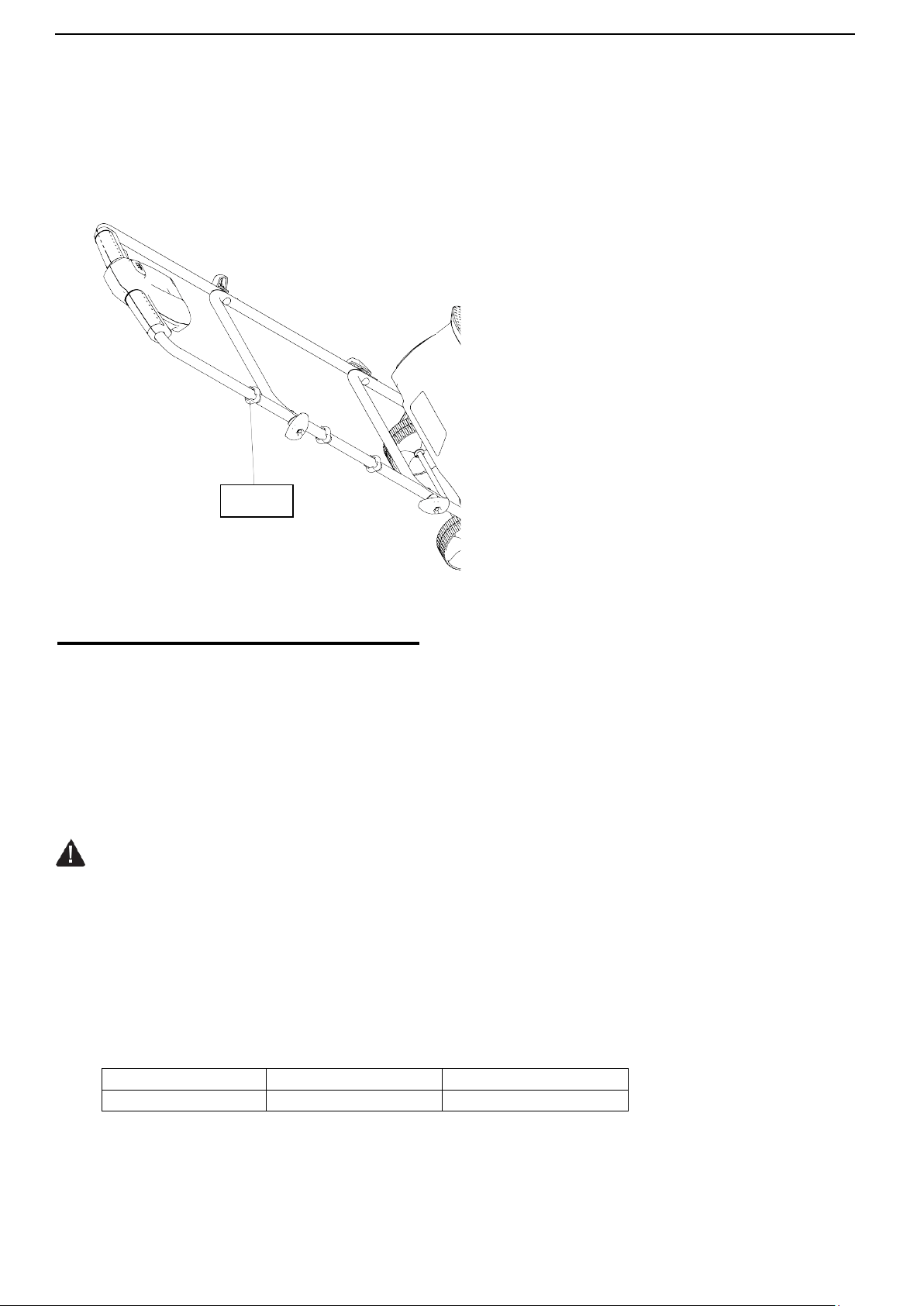
6. Locate the three cable clips in the parts bag. Secure the power cord to the frame of the unit by clipping them onto
the frame at evenly spaced intervals.
OPERATING INSTRUCTIONS
Note: Before using this machine, make sure that the power source you will use complies with the
specification’sdetailedinthismanual.Beforeinsertingtheplugintothesocket, verify that the snow throwers auger and
scraper are firmly attached with screws. Perform a test run to ensure that the rotor turns freely.
SECURING THE EXTENSION CORD
1. For safe and efficient use of your snow thrower, use only a UL-rated extension cord recommended for outdoor
use. Refer to the Extension Cord Chart below.
WARNING
Electric shock may cause SEVERE INJURY or DEATH. Heed these warnings:
• Do not allow any part of snow thrower to make contact with water while powered on. If the appliance becomes
wet while turned off, wipe dry before starting.
• Use only a UL-rated extension cord for outdoor, all-weather use. Do not use an extension cord more
than150feet long.
• Don't touch the appliance or its plug with wet hands or while standing in water. Wearing rubber boots offers
some protection.
EXTENTION CORD CHART
Cord Length
Up to 100 ft.
100-150ft.
Wire Gauge
14
12
Clip
12
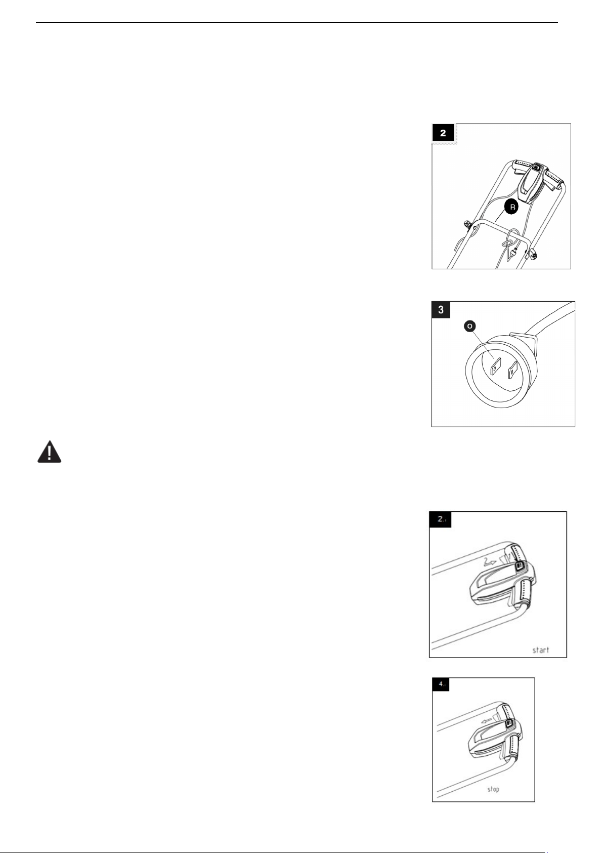
2. To prevent the extension cord from disconnecting during use, tie the female end of
the extension cord in to a loose knot on the top right side of the middle frame (B)
before connecting to the male plug in the socket of the snow thrower.
Note: The protective cover around the polarized plug is compatible with most extension
cords. When choosing an extension cord be sure the female end of your cord will fit
into the polarized plug.
3. Note that the snow thrower has a polarized male plug (O), with one prong in the
socket slightly longer and wider than the other. The extension cord female end
should be likewise polarized, so that the extension cord fits snugly into the socket.
WARNING
Damaged electrical cords present risk of fire, electric shock, and serious bodily injury.
Before operating the snow thrower, carefully examine the electrical cord. Id the cord is damaged, do not use the
snow thrower. Replace or repair the damaged cord immediately. If you need assistance, contact our customer
service department at 1-800-791-9458.
POWERING ON AND OFF
1. Connect extension cord to the male plug on the snow thrower then connect
extension cord to proper AC power source.
2. Press and Hold the switch button.
3. To start, while holding the switch button in, pull the handlebar toward you until it
touches the handle. The switch button must be pressed in and held before pulling the
handle. Once the snow thrower starts, release the switch button.
4. To stop, release switch button.

13
MOVING THE MACHINE AND PLOWING THE SNOW
WARNING
Foreign objects, such as rocks, broken glass, nails, wire, or string, can be picked up and thrown by the snow
thrower, causing serious personal injury.
Remove all foreign objects from the area to be plowed before operating the snow thrower.
Keep the area of operation free of foreign objects that can be become thrown by the rotor blades.
Perform a thorough inspection of the area since some objects may be hidden from view by surrounding
snow, If the snow thrower hits an obstruction or picks up a foreign object during use, stop the snow
thrower, disconnect the extension cord, remove the obstruction, and inspect the unit for damage.
Repair or replace any damaged parts before restarting and operating the unit.
Keep children, pets, and bystanders away from the area of operation. Be aware that the normal noise of the
machine when turned on may make it difficult for you to hear approaching people.
When moving the snow thrower, use the wheels on the sides as the pivot point. Slightly tilt the snow
thrower on this pivot point to move it forward or backward.
Start your clearing path near the electrical outlet and work outward, throwing snow in a back and forth
motion, To clear in the opposite direction, stop over the cord and pivot the snow thrower on its wheels.
Make sure to overlap clearing paths.
Note wind direction. If possible, move in the same direction as the wind so that the snow is not thrown
against the wind (and thus back into your face and back onto the patch).
While moving the snow thrower, do not drag the power cable violently or roughly. The snow thrower
should move within the range that the cable can reach.
Do not push the snow thrower with excessive force. You should push machine gently and evenly in
accordance with the units throw rate.
Some parts of the snow thrower may freeze under extreme temperature conditions. Do not attempt to
operate the snow thrower with frozen parts. If the parts freeze while the snow thrower is in use, stop the
snow thrower, unplug the extension cord, and inspect for frozen parts. Free all parts before operating the
snow thrower. Never force controls that have frozen.
Working on pebbles, gravel, or unpaved surfaces-To avoid throwing loose surface material along with the
snow, push down on the raise the scrapper at the base of the unit above the pebbles or gravel.
14
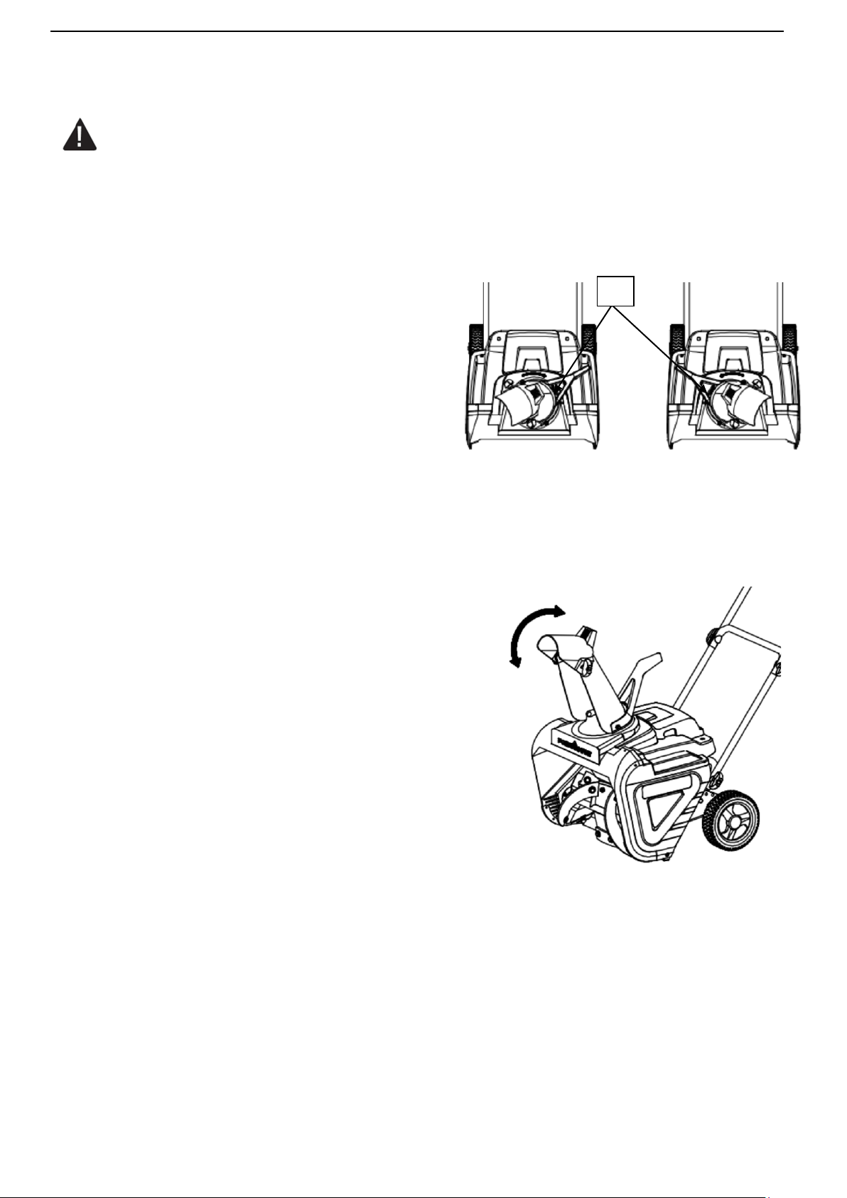
CHANGING THROW DIRECTION AND THROW HEIGHT
WARNING
Never direct the snow discharge chute at the operator, at bystanders, at vehicles or at nearby windows.
Discharge snow and foreign objects accidentally picked up by the snow thrower can cause serious damage and
personal injury.
Always orient the discharge chute in the opposite direction from where you, bystanders, surrounding vehicles,
or windows are located.
1. The discharge chute (H) can be adjusted 180 degrees
by rotating the chute crank. Rotate the chute control
crank clockwise to move the discharge chute (H) to
the left, counterclockwise to move the chute to the
right.
2. The chute deflector on the top of the discharge chute (H) controls the height of the snow stream. Loosen
both chute deflector knobs to raise or lower the deflector to the desired height you wish to throw the snow.
Tighten the knobs to secure the deflector.
Note: Do not over tighten the chute deflector knobs.
H
15
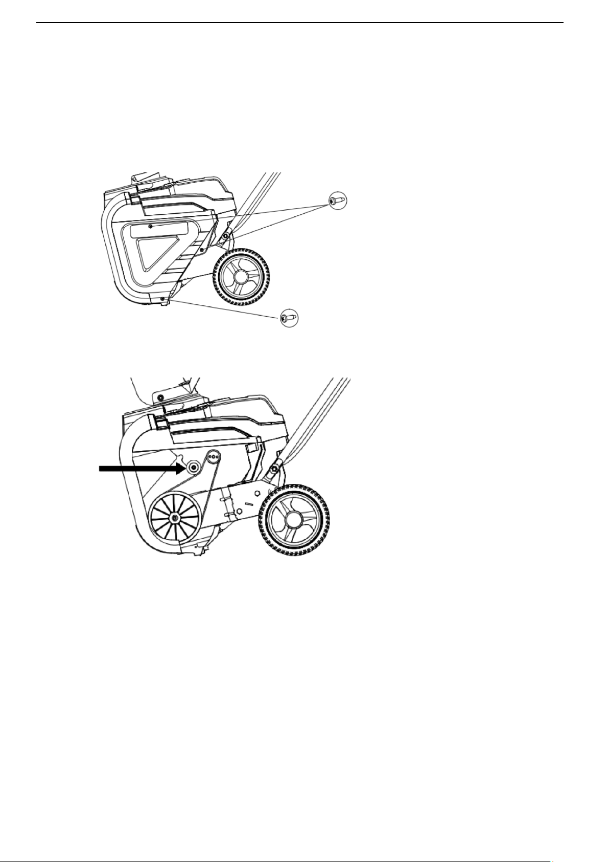
DRIVE BELT REPLACEMENT
WARNING Entanglement Hazard - Before performing any service procedures, make sure the snow thrower is
disconnected from the power source.
Note: Record component position before disassembly, to assist in reassembly.
1. Using screw driver, remove 3 screws attaching belt cover to housing.
2. Manually push the belt tension pulley up to reduce belt tension.
Note: When replacing the belt it is important to determine the cause of the failure (if applicable) and take
corrective action to avoid repeated failure.
3. Inspect the old belt, pulleys and tension spring before installing a new belt for damage and wear, replace
parts as required
4. Inspect the new belt to ensure it is the correct size and type.
Original – Part Number:5PJ720
5. Manuallypushthebelttensionpulleyuptoallowinstallationofthenewbelt.
6. Position the belt onto the small drive pulley, then while holding the belt tension pulley away from the belt,
carefully wind the belt onto the large pulley. Do not damage the new belt during installation.
7. Using screwdriver, install 3 screws attaching belt cover to housing.

16
TROUBLESHOOTING
Problem
Possible Causes
Remedy
WARNING - Before attempting to make any inspections, repairs or adjustments, stop the snow thrower, wait for
all moving parts to stop moving and carefully disconnect the AC extension cord from the power source.
No start
condition,
won't not
turn on
No power from AC
power source
Connect to known good AC power source
Extension cord not
connected
Securely connect extension cord at power source and
snow thrower
Extension cord faulty
Connect a known good extension cord
Improper starting
procedure
Review "Powering ON and OFF" procedure in this
manual
Auger damaged or
blocked
Check auger for damage, blockage or frozen
condition, repair as required
Faulty switch, wiring or
motor
Call customer service or contact service center
Turns on,
but won't
blow snow
Auger damaged or
blocked
Check auger for damage, blockage or frozen
condition, repair as required
Chute blocked or
damaged
Check chute for damage or blockage, repair as
required
Drive belt damaged
or loose
Check drive belt condition, repair as required (drive
belt is located on left side behind cover)
Turns on,
but won't
run at full
speed
Extension cord faulty
Connect a known good extension cord
Improper extension
cord
Check extension cord length and gauge for use in proper
application, Review "Extension Cord Chart" in this manual
Auger damaged or
blocked
Check auger for damage, blockage or frozen
condition, repair as required
Drive belt damaged or
loose
Check drive belt condition, repair as required (drive
belt is located on left side behind cover)
Faulty wiring or motor
Call customer service or contact service center

17
CARE AND MAINTENANCE
WARNING
Make sure to turn off the switch and disconnect the extension cord before performing any maintenance task on
your snow thrower.
Run the snow thrower for a few minutes to melt away any snow on the snow thrower. Turn the snow
thrower's power off.
Disconnect the extension cord from the snow thrower.
Examine the extension cord thoroughly for signs of wear or damage. Replace it if it is worn or damaged.
Examine the snow thrower thoroughly for worn, loose bolts or damaged parts. For repairing or replacing
parts, contact customer service.
Store the extension cord with the snow thrower.
Store the unit in a locked and dry or high and dry place to prevent unauthorized use/damage and keep out
of the reach of children. Store the instruction manual along with unit for future use.
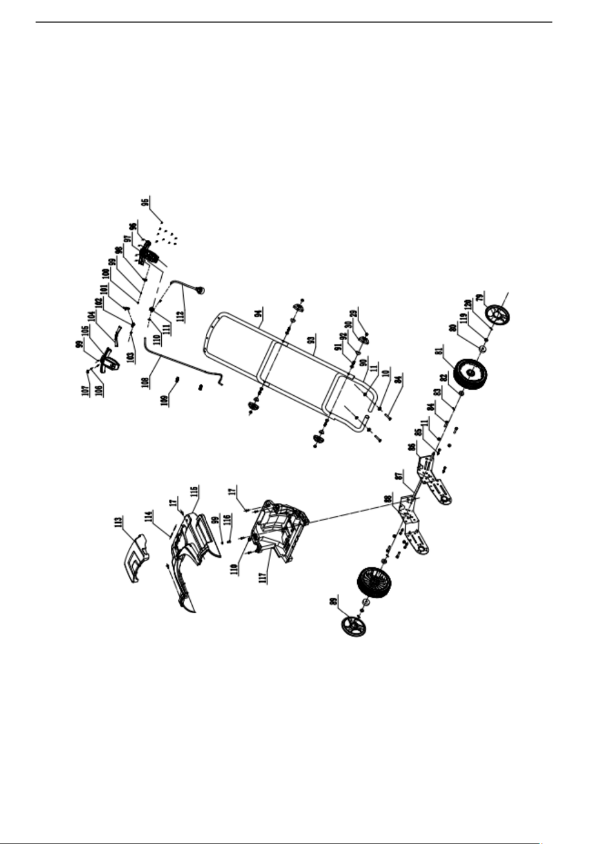
18
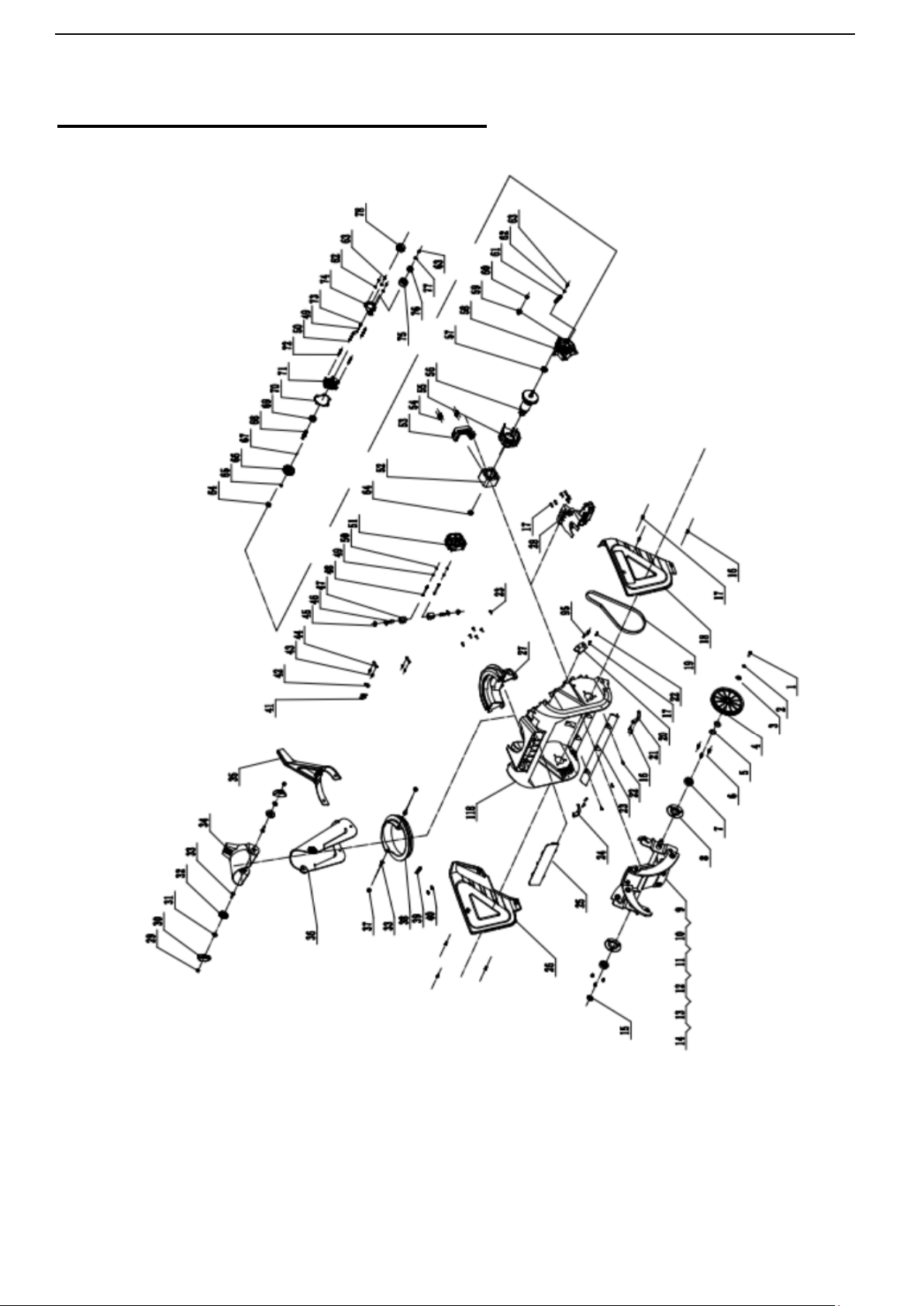
EXPLODED VIEW AND PART LIST
19

20
Item Stock # Description Qty
Item Stock # Description Qty
1 303020282 Hex Bolt M6x16 1
61 303130019 Tensioning Wheel Spring 1
2 303041009 Spring Washer 6 1
62 303042019 Flat Washer 4
3 303042009 Flat Washer 1
63 303020077 Bolt M4x10 5
4 203060009A Big Belt Wheel 1
64 303100023 Deep Groove Ball Bearing 2
5 303042069 Flat Washer 3
65 303050029 Shaft Ring 1
6 303020339 Hex Bolt M6x14 6
66 303160004 Big Gear 1
7 303100002
Deep Groove Ball
Bearing
2
67 303110020 Woodruff Key 1
8 303070797 Bearing Plate Welded 2
68 303160111 Output Shaft 1
9 303020106 Hex Bolt M8x20 12
69 303100024 Deep Groove Ball Bearing 1
10 303042013 Flat Washer 14
70 303070029 Oil Pad 1
11 303030036 Nut M8 14
71 303090002 End Cover 1
12 302110092 DB2801 Long Scraper 4
72 303010221 Screw ST4×40 2
13 302110091 DB2801 Short Scraper 2
73 303020079 Bolt M4x14 3
14 303181303
DB5021 Auger Shaft
Welded
1
74 303180588
Tension Wheel Brasket
Welded
1
15 303050066 Shaft Ring 17 1
75 203020077 Tension Wheel 1
16 303010284 Screw ST4.8×12 6
76 303100016
Deep Groove Ball Bearing
6000RS
1
17 303010176 Screw ST6.3×16 17
77 303042035 Flat Washer 1
18 203050654 Left Side Cover 1
78 303060005 Small Pulley 1
19 302040025 V-belt 1
79 203050658 Wheel Cover L 1
20 203050588 Motor Support Plate 1
80 303100034
Deep Groove Ball Bearing
6203Z
2
21 303070738 Left Corner 1
81 203050544 8" Wheel 2
22 303010312 Screw ST4.8×16 11
82 303100065 Wheel Bearing 2
23 303070741A Shovel 1
83 303160845 Butterfly Pin 2
24 303070739 Right Corner 1
84 303020124 Hex Bolt M8x35 6
25 203010747 LOGO Plate 1
85 303010353 Screw ST6.3x16 8
26 203050655 Right Side Cover 1
86 303071479 Left Support Plate 1
27 203050171 Deck 1
87 303181283 Shaft 1
28 203050567 Motor Bracket 1
88 303071480 Right Support Plate 1
29 303030066 Normal Hex Bolt M8 6
89 203021421 Wheel Cover R 1
30 203020336A Knob 6
90 303081214 Lower Tube 1
31 303042023 Flat Washer 2
91 303020057 T-screw 4
32 203020380 Pad 2
92 303043010 Concave Pad 4

21
33 303020161
Square Neck Bolt
M8x25
4
93 303081213 Middle Tube 1
34 203050174 Upper Chute 1
94 303081212 Upper Tube 1
35 203010648 Chute Handle 1
95 303010358 Screw ST4.2×14 10
36 203050175 Middle Chute 1
96 302070001 Oil Cap Seal Ring 4
37 303030077 Nut M8 2
97 203050660 Lower Switch Box 1
38 203050172 Rotating disc 1
98 303130013 Button Spring 1
39 203010647 Locating Piece 1
99 303042019 Flat Washer 1
40 303130138 Press Spring 2
100 303010313 Screw 3
41 301080009 Overcurrent Protector 1
101 203021102A Switch Button 1
42 306010037 Screw Cap 1
102 203010655 Push Rod 1
43 303010203 Screw 3x10 4
103 303130124 Spring 1
44 303070074 Brush Holder 2
104 203021101A Right Trigger 2
45 301110043 Brush Cover 2
105 203050552 Upper Switch Box 1
46 301110058 Electrical Carbon 2
106 303130125
Reverse Lock Button
Spring
1
47 301110044 Brush Component 2
107 203010656 Reverse Lock Button 1
48 303010162 Screw ST4×70 2
108 301040078A
Cable(120V)
1
49 303041008 Spring Washer φ4 5
109 203020065 Clip 2
50 303042038 Flat Washer 5
110 203020047 Cable Clamp 3
51 203020050 Rear Motor Bracket 1
111 301100046 Switch 1
52 301030008 Stator 1
112 301040045 Power Cord 1
53 203050587 Motor Holder 1
113 203050662 Battery Pack Cover 1
54 303010355 Screw ST6.3×20 4
114 303100086 Shaft 2
55 203020063 Front Motor Bracket 1
115 203050656 Upper Cover 1
56 301030005A Rotor 1
116 303010363 Screw 1
57 303100030
Deep Groove Ball
Bearing
1
117 203050657 Lower Cover 1
58 303090005 Middle Cover 1
118 203050170A Deck 1
59 203060019 Gear 1
119 303160887 Spacer 2
60 303030047 Nut M8 1
120 303121002 Cotter Pin 2

22
TWO (2) YEARS LIMITED WARRANTY
POWERSMART IS COMMITTED TO BUILDING TOOLS THAT ARE DEPENDABLE FOR YEARS. OUR
WARRANTIES ARE CONSISTENT WITH OUR COMMITMENT AND DEDICATION TO QUALITY.
TWO (2) YEARS LIMITED WARRANTY OF POWER SMART PRODUCTS FOR HOME USE.
POWERSMART (“SELLER") WARRANTS TO THE ORIGINAL PURCHASER ONLY, THAT ALL POWERSMART
CONSUMER POWER TOOLS WILL BE FREE FROM DEFECTS IN MATERIAL OR WORKMANSHIP FOR A
PERIOD OF TWO (2) YEARS FROM DATE OF PURCHASE. NINETY (90) DAYS FOR ALL POWERSMART
PRODUCTS, IF THE TOOL IS USED FOR PROFESSIONAL OR COMMERCIAL USE.
SELLER’S SOLE OBLIGATION AND YOUR EXCLUSIVE REMEDY UNDER THIS TWO (2) YEARS LIMITED
WARRANTY AND, TO THE EXTENT PERMITTED BY LAW, ANY WARRANTY OR CONDITION IMPLIED BY LAW,
SHALL BE THE REPAIR OR REPLACEMENT OF PARTS, WITHOUT CHARGE, WHICH ARE DEFECTIVE IN
MATERIAL OR WORKMANSHIP AND WHICH HAVE NOT BEEN MISUSED, CARELESSLY HANDLED, OR
MISREPAIRED BY PERSONS OTHER THAN SELLER OR AUTHORIZED SERVICE CENTER. TO MAKE A
CLAIM UNDER THIS LIMITED WARRANTY, YOU MUST RETURN THE ENTIRE POWER TOOL PRODUCT;
TRANSPORTATION PREPAID, TO POWERSMART INCLUDE A LEGIBLE COPY OF THE ORIGINAL RECEIPT,
WHICH LISTS THE DATE OF PURCHASE (MONTH AND YEAR) AND THE NAME OF THE COMPANY
PURCHASED FROM.
THIS LIMITED WARRANTY DOES NOT APPLY TO ANY ACCESSORY ITEMS INCLUDED WITH THE TOOL
SUCH AS CIRCULAR SAW BLADES OTHER RELATED ITEMS OR TO ANY REPLACEMENT PARTS LISTED
UNDER MAINTENANCE.
ANY IMPLIED WARRANTIES SHALL BE LIMITED IN DURATION TO TWO (2) YEARS FROM DATE OF
PURCHASE. SOME STATES IN THE U.S. AND SOME CANADIAN PROVINCES DO NOT ALLOW LIMITATIONS
ON HOW LONG AN IMPLIED WARRANTY LASTS, SO THE ABOVE LIMITATION MAY NOT APPLY TO YOU.
IN NO EVENT SHALL SELLER BE LIABLE FOR ANY INCIDENTAL OR CONSEQUENTIAL DAMAGES
(INCLUDING BUT NOT LIMITED TO LIABILITY FOR LOSS OF PROFITS) ARISING FROM THE SALE OR USE
OF THIS PRODUCT. SOME STATES IN THE U.S. AND SOME CANADIAN PROVINCES DO NOT ALLOW THE
EXCLUSION OR LIMITATION OF INCIDENTAL OR CONSEQUENTIAL DAMAGES, SO THE ABOVE
LIMITATION OR EXCLUSION MAY NOT APPLY TO YOU.
THIS LIMITED WARRANTY GIVES YOU SPECIFIC LEGAL RIGHTS, AND YOU MAY ALSO HAVE OTHER
RIGHTS WHICH VARY FROM STATE TO STATE IN THE U.S., PROVINCE TO PROVINCE IN CANADA AND
FROM COUNTRY TO COUNTRY.
FOR QUESTIONS / COMMENTS, TECHNICAL ASSISTANCE OR REPAIR PARTS – PLEASE CALL TOLL FREE
AT: 1-800-791-9458 (M-F 9AM – 5PM EST) EMAIL: SUPPORT@AMERISUNINC.COM
SAVE YOUR RECEIPTS. THIS WARRANTY IS VOID WITHOUT THEM.
