
1
4
2
5
3
6
Cat. No. E5325DI-000-E5325-02A
Installation Instructions
TAMPER-RESISTANT OUTLET
15A-125V
decora edge
™
SAFER, FASTER, and EASIER
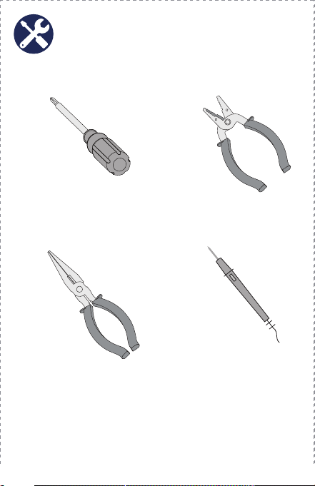
Recommended Tools
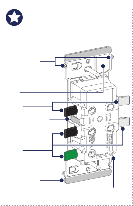
Features
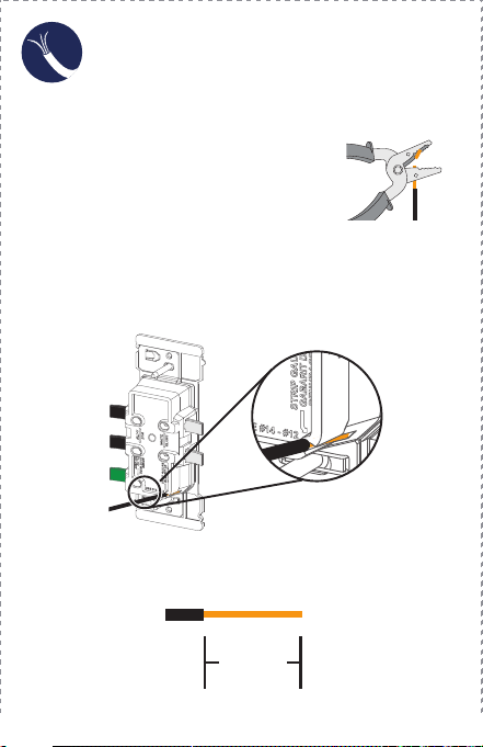
Preparing Wires
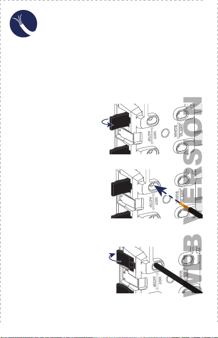
Lever Wiring Feature
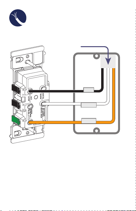
Wiring Your Device
If you need help...
ONLINE
www.leviton.com/support
CHAT
www.leviton.com/contact
CALL
1-800-824-3005 (USA)
1-800-405-5320 (Canada)
Leviton Manufacturing Co., Inc.
201 North Service Road, Melville, NY 11747
© 2022 Leviton Manufacturing Co., Inc. All rights reserved.
Specifications subject to change at any time without notice.
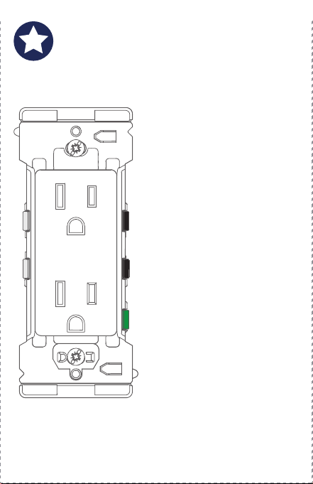
Leviton’s Decora Edge
Tamper-Resistant Outlet
makes it safer, faster, and
easier to install a new outlet.
Colored levers easily identify
where to connect each wire.
There are no exposed wires or
metal parts after installation.
Built-in strip gauge.
An extra large plastic strap
facilitates installation in large
wall openings.
Designed for midway
wallplates for extra coverage,
or you can easily convert it to
use with standard wallplates
by removing the break-off tabs.
Built-in alignment feature
to align other Decora Edge
products in a multi-gang
installation. (See page 13.)
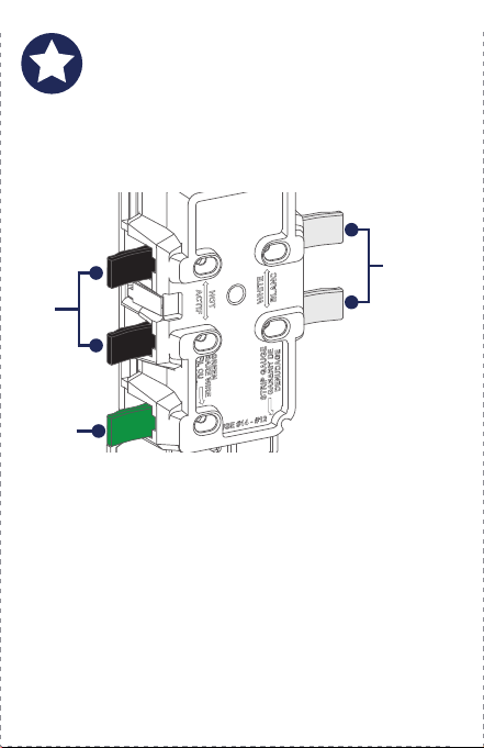
Terminates wire with a snap
The colored levers snap shut to terminate the wires.
Levers
Le
vers
Strip Gauge
Strap
Alignment Tab
and Notch
Aligns devices for
multi-
gang installations.
Split Circuit Cover
Covers the split
c
ircuit tab from live
wire access. Break
off for split circuits.
Break-off Fins
Break off to install a
standard
size wallplate.
The color-coded levers easily identify where to connect
the wallbox wires to the outlet.
NOTE: Wire colors in your wallbox may be different from
the lever colors. See “Preparing Wires,” on page 5 to
make sure you insert the wires properly
.
Line/
Lo
ad
Levers
Ground
Lever
Neutral
Levers
Slotted/Phillips Screwdriver
Needle Nose Pliers
Wire Stripper
Voltage Tester
(measure bare wire here)
Use Built-in
Strip Gauge on the Outlet
Use Strip Gauge
as shown below
1. M
ake sure that the ends of the
wires from the wallbox are straight
(cut if necessary).
2. S
trip each wire in the wallbox, as shown below.
OR
9/16 in.
(1.4 cm)
WARNING: TO AVOID FIRE, SHOCK, OR DEATH, TURN
OFF POWER at circuit breaker or fuse and test that power
is OFF before wiring!
1. Remove the existing outlet.
2. V
erify that you have a Line (Black) wire, Neutral
(White) wire, and a Ground (Bare Copper or
Green) wire.
NOTE: W
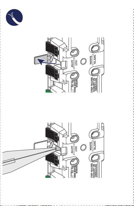
ork on only one connection at a time.
3. Fully open lever
.
5. Fully close lever.
4. Insert the proper wire per
lever color into the wire
hole. Make sure the wire
is fully inserted and no
bare wire is exposed.
6. To complete wiring, proceed to page 7 or 8.
NOTES:
•
Use with #12 AWG or #14 AWG solid or stranded wire only.
• DO NOT use copper clad wires with this device.
NOTE: If using stranded
wire twist wire
before insertion.
WEB VERSION
1
4
2
5
3
6
Cat. No. E5325DI-000-E5325-02A
Installation Instructions
TAMPER-RESISTANT OUTLET
15A-125V
decora edge
™
SAFER, FASTER, and EASIER
Recommended Tools
Features
Preparing Wires
Lever Wiring Feature
Wiring Your Device
If you need help...
ONLINE
www.leviton.com/support
CHAT
www.leviton.com/contact
CALL
1-800-824-3005 (USA)
1-800-405-5320 (Canada)
Leviton Manufacturing Co., Inc.
201 North Service Road, Melville, NY 11747
© 2022 Leviton Manufacturing Co., Inc. All rights reserved.
Specifications subject to change at any time without notice.
Leviton’s Decora Edge
Tamper-Resistant Outlet
makes it safer, faster, and
easier to install a new outlet.
Colored levers easily identify
where to connect each wire.
There are no exposed wires or
metal parts after installation.
Built-in strip gauge.
An extra large plastic strap
facilitates installation in large
wall openings.
Designed for midway
wallplates for extra coverage,
or you can easily convert it to
use with standard wallplates
by removing the break-off tabs.
Built-in alignment feature
to align other Decora Edge
products in a multi-gang
installation. (See page 13.)
Terminates wire with a snap
The colored levers snap shut to terminate the wires.
Levers
Le
vers
Strip Gauge
Strap
Alignment Tab
and Notch
Aligns devices for
multi-
gang installations.
Split Circuit Cover
Covers the split
c
ircuit tab from live
wire access. Break
off for split circuits.
Break-off Fins
Break off to install a
standard
size wallplate.
The color-coded levers easily identify where to connect
the wallbox wires to the outlet.
NOTE: Wire colors in your wallbox may be different from
the lever colors. See “Preparing Wires,” on page 5 to
make sure you insert the wires properly
.
Line/
Lo
ad
Levers
Ground
Lever
Neutral
Levers
Slotted/Phillips Screwdriver
Needle Nose Pliers
Wire Stripper
Voltage Tester
(measure bare wire here)
Use Built-in
Strip Gauge on the Outlet
Use Strip Gauge
as shown below
1. M
ake sure that the ends of the
wires from the wallbox are straight
(cut if necessary).
2. S
trip each wire in the wallbox, as shown below.
OR
9/16 in.
(1.4 cm)
WARNING: TO AVOID FIRE, SHOCK, OR DEATH, TURN
OFF POWER at circuit breaker or fuse and test that power
is OFF before wiring!
1. Remove the existing outlet.
2. V
erify that you have a Line (Black) wire, Neutral
(White) wire, and a Ground (Bare Copper or
Green) wire.
NOTE: W
ork on only one connection at a time.
3. Fully open lever
.
5. Fully close lever.
4. Insert the proper wire per
lever color into the wire
hole. Make sure the wire
is fully inserted and no
bare wire is exposed.
6. To complete wiring, proceed to page 7 or 8.
NOTES:
•
Use with #12 AWG or #14 AWG solid or stranded wire only.
• DO NOT use copper clad wires with this device.
NOTE: If using stranded
wire twist wire
before insertion.
WEB VERSION
7
11
8
12
9
13
10
Split Circuit Wiring
Split Circuit Wiring
(continued)
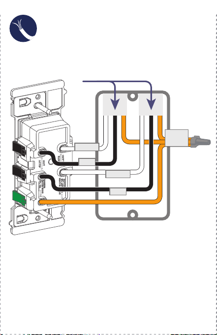
Common Feed Wiring
Single-Gang Box Installation
Test
Multi-Gang Box Installation Safety First
Limited 2 Year Warranty & Exclusions
WARNINGS:
• TO AVOID FIRE SHOCK OR DEATH; TURN OFF POWER at circuit
b
reaker or fuse when servicing, installing or removing device.
• T
his product is to be installed and/or used in accordance with
electrical codes and regulations.
• I
f you are unsure about any part of these instructions,
consult an electrician.
CAUTIONS:
• U
se this device with solid or stranded copper wire only.
• DO NOT use this device with copper clad wire.
• T
o avoid damage to the product, DO NOT use disinfecting products,
including foggers, sprays or other types of atomized cleaning agents.
• DO
NOT spray liquid onto the product.
• To clean, use a damp cloth with mild soap.
F
or Leviton’s limited product warranty, go to www.leviton.com. For a
p
rinted copy of the warranty, call 1-800-824-3005.
FOR CANADA ONLY
For warranty information and/or product returns, residents of Canada
should contact Leviton in writing at Leviton Manufacturing of
Canada
ULC to the attention of the Quality Assurance Department,
1
65 Hymus Blvd, Pointe-Claire (Quebec), Canada H9R 1E9 or by
telephone at 1 800 405-5320.
PATENT STATEMENT
Patents covering this product, if any, can be found on
Leviton.com/patents.
2. Break off split circuit tab and then close cover.
3. Connect the wires as shown.1. Connect the wires as shown.
If your back box looks different,
consult
an electrician
If your back box looks different,
consult an electrician
GROUND
LINE
NEUTRAL
LINE
NEUTRAL
From
From
Branch CircuitBranch Circuit
LINE
NEUTRAL
GROUND
From
From
Branch CircuitBranch Circuit
WARNING: Turn the power OFF at the breaker or
fuse before you complete the installation.
3. Restore power at the circuit breaker or fuse.
4. T
est outlet.
5. T
o complete the installation, proceed to the next page.
If you are unsure about the installation process,
c
ontact Leviton Technical Support,
or contact an electrician.
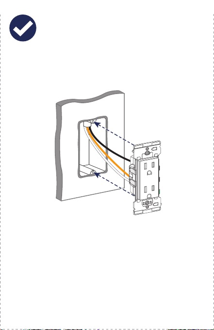
1. Position all wires so that there is room in the wallbox
for the device.
2. Partially screw the mounting screws into the wallbox’
s
mounting holes.
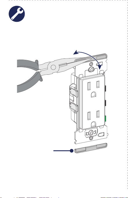
The outlet strap is designed for midway wallplates.
If you want to use a standard size wallplate, carefully
remove both break-off fins, as shown below.
Remove
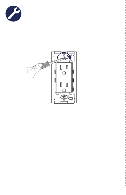
WARNING: Turn the power OFF at the circuit breaker
before you tighten the screws.
1. T
ighten the mounting screws into wallbox.
2. Install wallplate, and restore power
.
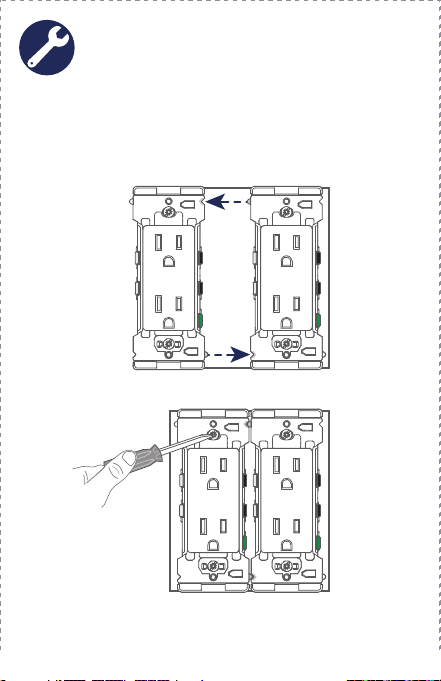
WARNING: Turn the power OFF at the circuit breaker
before you tighten the screws.
2. T
ighten the mounting screws into wallbox.
1. T
o install the outlet next to other Decora Edge devices,
use the alignment feature to easily place each device
next to each other in the multi-gang box.
3. Install wallplate, and restore power
.
Visit leviton.com/support or contact Technical
Services at 1-800-824-3005 for additional help.
Scan this QR code for additional
Decora Edge product information
and to view the install video.
Wallplate Installation
Preparation
1. Open split circuit cover.
WEB VERSION
7
11
8
12
9
13
10
Split Circuit Wiring
Split Circuit Wiring
(continued)
Common Feed Wiring
Single-Gang Box Installation
Test
Multi-Gang Box Installation Safety First
Limited 2 Year Warranty & Exclusions
WARNINGS:
• TO AVOID FIRE SHOCK OR DEATH; TURN OFF POWER at circuit
b
reaker or fuse when servicing, installing or removing device.
• T
his product is to be installed and/or used in accordance with
electrical codes and regulations.
• I
f you are unsure about any part of these instructions,
consult an electrician.
CAUTIONS:
• U
se this device with solid or stranded copper wire only.
• DO NOT use this device with copper clad wire.
• T
o avoid damage to the product, DO NOT use disinfecting products,
including foggers, sprays or other types of atomized cleaning agents.
• DO
NOT spray liquid onto the product.
• To clean, use a damp cloth with mild soap.
F
or Leviton’s limited product warranty, go to www.leviton.com. For a
p
rinted copy of the warranty, call 1-800-824-3005.
FOR CANADA ONLY
For warranty information and/or product returns, residents of Canada
should contact Leviton in writing at Leviton Manufacturing of
Canada
ULC to the attention of the Quality Assurance Department,
1
65 Hymus Blvd, Pointe-Claire (Quebec), Canada H9R 1E9 or by
telephone at 1 800 405-5320.
PATENT STATEMENT
Patents covering this product, if any, can be found on
Leviton.com/patents.
2. Break off split circuit tab and then close cover.
3. Connect the wires as shown.1. Connect the wires as shown.
If your back box looks different,
consult
an electrician
If your back box looks different,
consult an electrician
GROUND
LINE
NEUTRAL
LINE
NEUTRAL
From
From
Branch CircuitBranch Circuit
LINE
NEUTRAL
GROUND
From
From
Branch CircuitBranch Circuit
WARNING: Turn the power OFF at the breaker or
fuse before you complete the installation.
3. Restore power at the circuit breaker or fuse.
4. T
est outlet.
5. T
o complete the installation, proceed to the next page.
If you are unsure about the installation process,
c
ontact Leviton Technical Support,
or contact an electrician.
1. Position all wires so that there is room in the wallbox
for the device.
2. Partially screw the mounting screws into the wallbox’
s
mounting holes.
The outlet strap is designed for midway wallplates.
If you want to use a standard size wallplate, carefully
remove both break-off fins, as shown below.
Remove
WARNING: Turn the power OFF at the circuit breaker
before you tighten the screws.
1. T
ighten the mounting screws into wallbox.
2. Install wallplate, and restore power
.
WARNING: Turn the power OFF at the circuit breaker
before you tighten the screws.
2. T
ighten the mounting screws into wallbox.
1. T
o install the outlet next to other Decora Edge devices,
use the alignment feature to easily place each device
next to each other in the multi-gang box.
3. Install wallplate, and restore power
.
Visit leviton.com/support or contact Technical
Services at 1-800-824-3005 for additional help.
Scan this QR code for additional
Decora Edge product information
and to view the install video.
Wallplate Installation
Preparation
1. Open split circuit cover.
WEB VERSION
7
11
8
12
9
13
10
Split Circuit Wiring
Split Circuit Wiring
(continued)
Common Feed Wiring
Single-Gang Box Installation
Test
Multi-Gang Box Installation Safety First
Limited 2 Year Warranty & Exclusions
WARNINGS:
• TO AVOID FIRE SHOCK OR DEATH; TURN OFF POWER at circuit
b
reaker or fuse when servicing, installing or removing device.
• T
his product is to be installed and/or used in accordance with
electrical codes and regulations.
• I
f you are unsure about any part of these instructions,
consult an electrician.
CAUTIONS:
• U
se this device with solid or stranded copper wire only.
• DO NOT use this device with copper clad wire.
• T
o avoid damage to the product, DO NOT use disinfecting products,
including foggers, sprays or other types of atomized cleaning agents.
• DO
NOT spray liquid onto the product.
• To clean, use a damp cloth with mild soap.
F
or Leviton’s limited product warranty, go to www.leviton.com. For a
p
rinted copy of the warranty, call 1-800-824-3005.
FOR CANADA ONLY
For warranty information and/or product returns, residents of Canada
should contact Leviton in writing at Leviton Manufacturing of
Canada
ULC to the attention of the Quality Assurance Department,
1
65 Hymus Blvd, Pointe-Claire (Quebec), Canada H9R 1E9 or by
telephone at 1 800 405-5320.
PATENT STATEMENT
Patents covering this product, if any, can be found on
Leviton.com/patents.
2. Break off split circuit tab and then close cover.
3. Connect the wires as shown.1. Connect the wires as shown.
If your back box looks different,
consult
an electrician
If your back box looks different,
consult an electrician
GROUND
LINE
NEUTRAL
LINE
NEUTRAL
From
From
Branch Circuit
Branch Circuit
LINE
NEUTRAL
GROUND
From
From
Branch Circuit
Branch Circuit
WARNING: Turn the power OFF at the breaker or
fuse before you complete the installation.
3. Restore power at the circuit breaker or fuse.
4. T
est outlet.
5. T
o complete the installation, proceed to the next page.
If you are unsure about the installation process,
c
ontact Leviton Technical Support,
or contact an electrician.
1. Position all wires so that there is room in the wallbox
for the device.
2. Partially screw the mounting screws into the wallbox’
s
mounting holes.
The outlet strap is designed for midway wallplates.
If you want to use a standard size wallplate, carefully
remove both break-off fins, as shown below.
Remove
WARNING: Turn the power OFF at the circuit breaker
before you tighten the screws.
1. T
ighten the mounting screws into wallbox.
2. Install wallplate, and restore power
.
WARNING: Turn the power OFF at the circuit breaker
before you tighten the screws.
2. T
ighten the mounting screws into wallbox.
1. T
o install the outlet next to other Decora Edge devices,
use the alignment feature to easily place each device
next to each other in the multi-gang box.
3. Install wallplate, and restore power
.
Visit leviton.com/support or contact Technical
Services at 1-800-824-3005 for additional help.
Scan this QR code for additional
Decora Edge product information
and to view the install video.
Wallplate Installation
Preparation
1. Open split circuit cover.
WEB VERSION

1
4
2
5
3
6
Cat. No. E5325DI-000-E5325-02A
Installation Instructions
TAMPER-RESISTANT OUTLET
15A-125V
decora edge
™
SAFER, FASTER, and EASIER
Recommended Tools
Features
Preparing Wires
Lever Wiring Feature
Wiring Your Device
If you need help...
ONLINE
www.leviton.com/support
CHAT
www.leviton.com/contact
CALL
1-800-824-3005 (USA)
1-800-405-5320 (Canada)
Leviton Manufacturing Co., Inc.
201 North Service Road, Melville, NY 11747
© 2022 Leviton Manufacturing Co., Inc. All rights reserved.
Specifications subject to change at any time without notice.
Leviton’s Decora Edge
Tamper-Resistant Outlet
makes it safer, faster, and
easier to install a new outlet.
Colored levers easily identify
where to connect each wire.
There are no exposed wires or
metal parts after installation.
Built-in strip gauge.
An extra large plastic strap
facilitates installation in large
wall openings.
Designed for midway
wallplates for extra coverage,
or you can easily convert it to
use with standard wallplates
by removing the break-off tabs.
Built-in alignment feature
to align other Decora Edge
products in a multi-gang
installation. (See page 13.)
Terminates wire with a snap
The colored levers snap shut to terminate the wires.
Levers
Le
vers
Strip Gauge
Strap
Alignment Tab
and Notch
Aligns devices for
multi-
gang installations.
Split Circuit Cover
Covers the split
c
ircuit tab from live
wire access. Break
off for split circuits.
Break-off Fins
Break off to install a
standard
size wallplate.
The color-coded levers easily identify where to connect
the wallbox wires to the outlet.
NOTE: Wire colors in your wallbox may be different from
the lever colors. See “Preparing Wires,” on page 5 to
make sure you insert the wires properly
.
Line/
Lo
ad
Levers
Ground
Lever
Neutral
Levers
Slotted/Phillips Screwdriver
Needle Nose Pliers
Wire Stripper
Voltage Tester
(measure bare wire here)
Use Built-in
Strip Gauge on the Outlet
Use Strip Gauge
as shown below
1. M
ake sure that the ends of the
wires from the wallbox are straight
(cut if necessary).
2. S
trip each wire in the wallbox, as shown below.
OR
9/16 in.
(1.4 cm)
WARNING: TO AVOID FIRE, SHOCK, OR DEATH, TURN
OFF POWER at circuit breaker or fuse and test that power
is OFF before wiring!
1. Remove the existing outlet.
2. V
erify that you have a Line (Black) wire, Neutral
(White) wire, and a Ground (Bare Copper or
Green) wire.
NOTE: W
ork on only one connection at a time.
3. Fully open lever
.
5. Fully close lever.
4. Insert the proper wire per
lever color into the wire
hole. Make sure the wire
is fully inserted and no
bare wire is exposed.
6. To complete wiring, proceed to page 7 or 8.
NOTES:
•
Use with #12 AWG or #14 AWG solid or stranded wire only.
• DO NOT use copper clad wires with this device.
NOTE: If using stranded
wire twist wire
before insertion.
WEB VERSION
