
Loading ...
Loading ...
Loading ...
GXT002429—UN—16JUL15
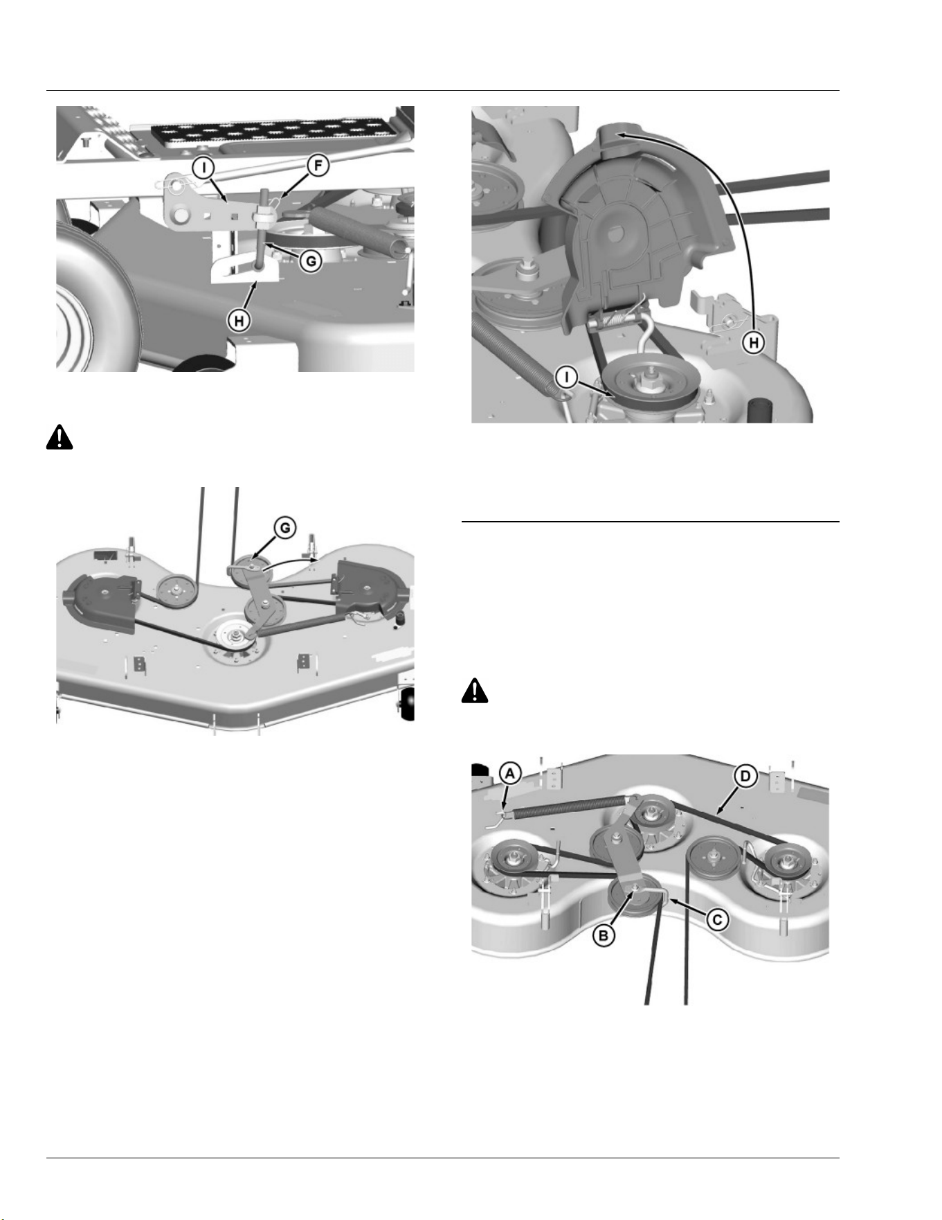
5. Install front hanger rod (G) onto the mower deck brackets (H) and
onto draft brackets (I). Secure each stud end with locking clip (F).
CAUTION: Avoid injury! Component is spring-assisted and
under tension. Injury can occur if spring-assisted
component is released suddenly.
GXT002218—UN—31JUL15
6. Connect mower drive belt:
● Install belt onto the engine sheave.
IMPORTANT: Avoid damage! Failure to install belt properly on
left and right spindle sheaves may result in belt damage.
Ensure proper installation of the belt on spindle sheaves.
● Insert 3/8 inch ratchet onto the square hole (G) in the tension
arm. Rotate arm clockwise and hold to release spring tension on
idler sheave.
GXT002520—UN—31JUL15
● Lift left spindle cover (H) and install mower belt (I) onto left
spindle sheave. Release spindle cover and tension arm.
● Flip up left and right spindle covers to check that belt is correctly
routed on all sheaves.
SB31882,00003F5-19-16JUN20
Replacing Mower Drive Belt
NOTE: The following procedure is for the 48HC mower deck. All
mower decks listed use a similar conguration of sheaves.
1. Park machine safely. (See Parking Safely in Safety section.)
2. Allow engine and muer to cool completely.
3. Remove mower deck.
CAUTION: Avoid injury! Components are installed under
spring tension. Wear eye protection and use proper tools
when installing and removing components with spring
tension.
GXT002808—UN—09JUN16
4. Remove deck drive belt as follows:
a. Remove spring from spring hook (A) on deck.
b. Remove nut (B) on the tension sheave and lower bolt to
remove guide (C). Remove belt (D) from all sheaves.
5. Inspect belt for wear or damage; replace as necessary.
6. Clean top surface of the mower deck and sheaves.
Service Mower
48
Loading ...
Loading ...
Loading ...