
Loading ...
Loading ...
Loading ...
Specication
Z515E, Z530M, Z530R, Z545R Spark
Plugs—Torque. . . . . . . . . . . . . . . . . . . . . . . . . . . . . . . . . . . . . . . . . . 20 N·m (14.75 lb·ft)
9. Connect spark plug wires.
SB31882,0000402-19-21AUG20
Replacing Fuel Filter
CAUTION: Avoid injury! Fuel vapors are explosive and
ammable:
• Do not smoke while handling fuel.
• Keep fuel away from ames or sparks.
• Shut o engine before servicing.
• Allow the engine to cool before servicing.
• Work in a well-ventilated area.
• Clean up spilled fuel immediately.
NOTE: Change lter when fuel is low.
1. Park machine safely. (See Parking Safely in the Safety section.)
2. Let engine cool.
3. Raise operator’s seat if necessary.
4. Put a drain pan under the fuel lter.
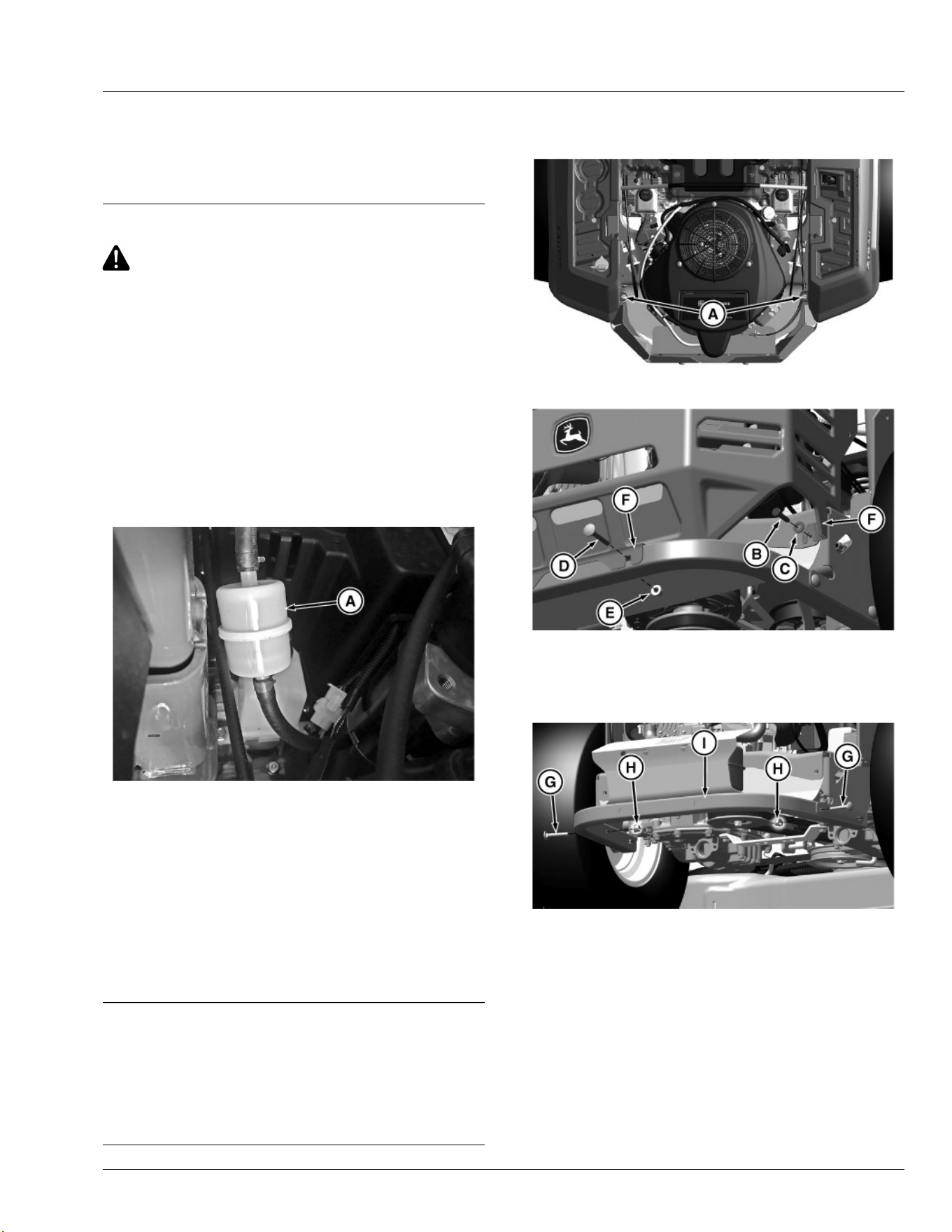
MX101641—UN—02SEP20
5. Slide hose clamps on both sides of the fuel lter (A) away from the
fuel lter ends using pliers.
6. Disconnect hoses from the lter.
IMPORTANT: Avoid damage! Incorrect installation of the fuel lter
may cause engine damage. Install the lter with the arrow
pointing in the direction of fuel ow (towards the engine) for
proper operation.
7. Connect hoses to a new lter making sure that the lter arrow is
pointing in the direction of the fuel ow.
8. Install clamps and check for leaks.
SB31882,0000403-19-04SEP20
Spark Arrestor Maintenance (If Equipped)
Spark arrestor assemblies include a screen element that should be
inspected and cleaned periodically. Visually inspect the screen for
tears, broken wires, or loose welds. Replace the spark arrestor
assembly if any of these conditions exist. If the screen is determined to
be in good condition, proceed with cleaning the screen by brushing
away loose dirt or carbon using a brush.
RM87422,00002DA-19-05JUL17
Cleaning Spark Arrestor
Z515E, Z530M, Z530R
MX101642—UN—02SEP20
1. Remove two push retainers (A) from the machine.
MX101479—UN—09MAY20
2. Remove two bolts (B), washers (C), carriage bolts (D), and lock
nuts (E) from the engine guard (F).
3. Repeat for the opposite side.
4. Remove the engine guard.
MX101502—UN—09MAY20
5. Remove two carriage bolts (G) and lock nuts (H) on each side of
the frame tube.
6. Remove the frame tube (I).
Service Engine
39
Loading ...
Loading ...
Loading ...