Loading ...
Loading ...
Loading ...

1507/1503
Users Manual
14
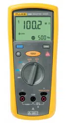
Measuring Insulation Resistance
Insulation tests should only be performed on de-energized
circuits. To measure insulation resistance set up the
Tester as shown in Figure 7 and follow the steps below:
1. Insert test probes in the V and COM input terminals.
2. Turn the rotary switch to the desired test voltage.
3. Connect the probes to the circuit to be measured. The
Tester automatically detects if the circuit is energized.
• The primary display shows until you press
and a valid insulation resistance reading
is obtained.
• The high voltage symbol () along with a primary
display of >30 V warns if voltage more than 30 V
ac or dc is present. In this condition, the test is
inhibited. Disconnect the Tester and remove
power before proceeding.
4. Push and hold to start the test. The secondary
display shows the test voltage applied to the circuit
under test. The high voltage symbol () along with a
primary display showing the resistance in MΩ or GΩ
appears. The
icon appears on the lower portion of
the display until is released.
When resistance is higher than the maximum display
range, the Tester displays the symbol and the
maximum resistance for the range.
5. Keep the probes on the test points and release the
button. The circuit under test then discharges
through the Tester. The resistance reading appears
on the primary display until a new test is started or a
different function or range is selected or >30 V is
detected.
1.888.610.7664 sales@GlobalTestSupply.com
Fluke-Direct.com
Loading ...
Loading ...
Loading ...