Loading ...
Loading ...
Loading ...
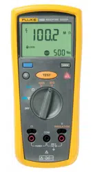
Insulation Testers
Making Measurements
13
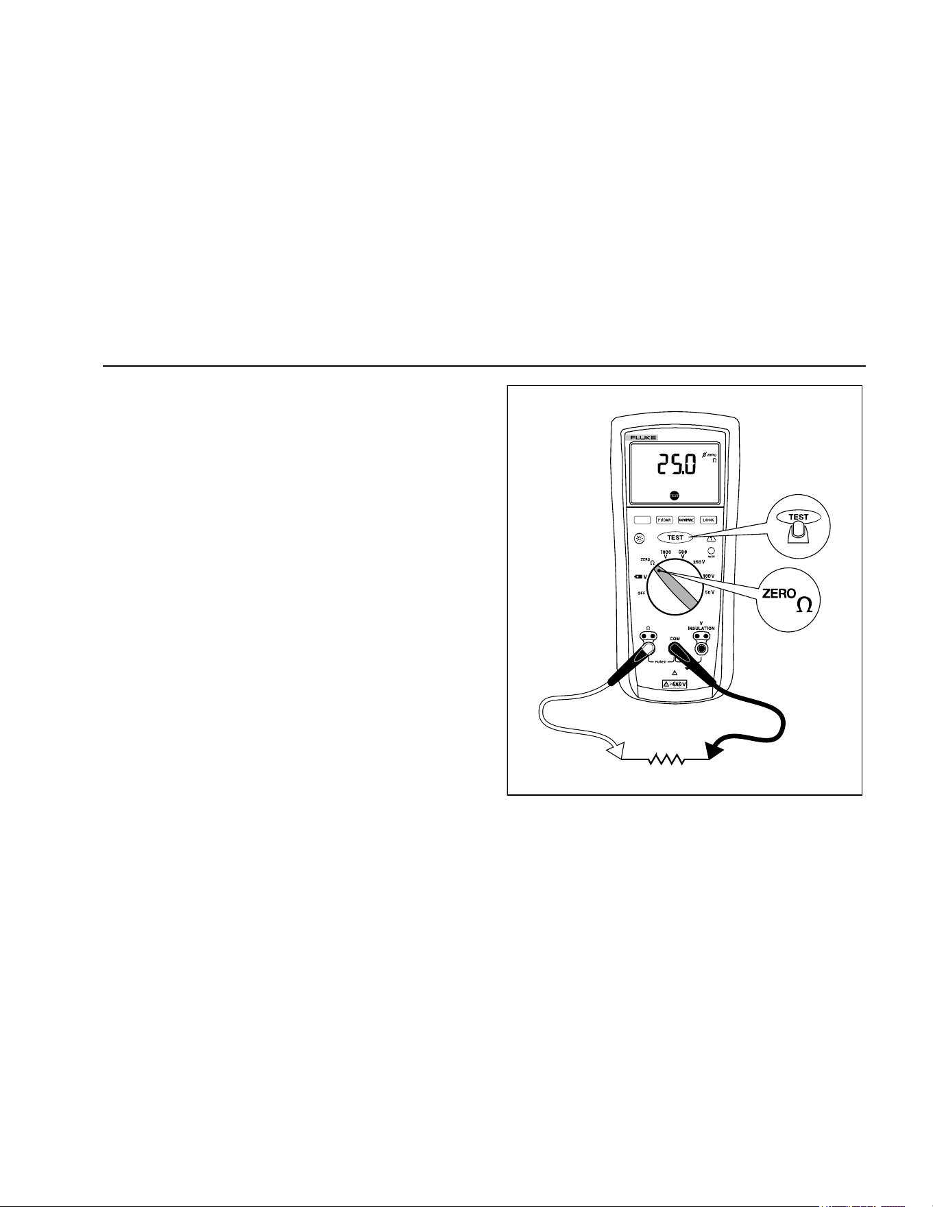
• The primary display shows ---- until you press the
button and a valid resistance reading is
obtained.
• The high voltage symbol (Y) along with a primary
display of >2 V warns if voltage greater than 2 V
ac or dc is present. In this condition, the test is
inhibited. Disconnect the Tester and remove
power before proceeding.
• If the Tester chirps when you press the
button, the test is inhibited because voltage is
present at the probes.
5. Push and hold the button to start the test. The
icon appears on the lower portion of the display
until you release the button. The resistance
reading appears on the primary display until a new
test is started or a different function or range is
selected.
When resistance is higher than the maximum display
range, the Tester displays the > symbol and the
maximum resistance for the range.
.
INSULATION TESTER
1507
bbw04f.emf
Figure 6. Measuring Earth-Bond Resistance
1.888.610.7664 sales@GlobalTestSupply.com
Fluke-Direct.com
Loading ...
Loading ...
Loading ...