
1507/1503
Insulation Testers
Users Manual
June 2005 Rev. 1, 2/19
2005-2019 Fluke Corporation. All rights reserved.
All product names are trademarks of their respective companies.
1.888.610.7664 sales@GlobalTestSupply.com
Fluke-Direct.com

LIMITED WARRANTY AND LIMITATION OF LIABILITY
Each Fluke product is warranted to be free from defects in material and workmanship under normal use and service. The warranty period is one year
and begins on the date of shipment. Parts, product repairs, and services are warranted for 90 days. This warranty extends only to the original buyer or
end-user customer of a Fluke authorized reseller, and does not apply to fuses, disposable batteries, or to any product which, in Fluke's opinion, has
been misused, altered, neglected, contaminated, or damaged by accident or abnormal conditions of operation or handling. Fluke warrants that soft-
ware will operate substantially in accordance with its functional specifications for 90 days and that it has been properly recorded on non-defective
media. Fluke does not warrant that software will be error free or operate without interruption.
Fluke authorized resellers shall extend this warranty on new and unused products to end-user customers only but have no authority to extend a
greater or different warranty on behalf of Fluke. Warranty support is available only if product is purchased through a Fluke authorized sales outlet or
Buyer has paid the applicable international price. Fluke reserves the right to invoice Buyer for importation costs of repair/replacement parts when
product purchased in one country is submitted for repair in another country.
Fluke's warranty obligation is limited, at Fluke's option, to refund of the purchase price, free of charge repair, or replacement of a defective product
which is returned to a Fluke authorized service center within the warranty period.
To obtain warranty service, contact your nearest Fluke authorized service center to obtain return authorization information, then send the product to
that service center, with a description of the difficulty, postage and insurance prepaid (FOB Destination). Fluke assumes no risk for damage in transit.
Following warranty repair, the product will be returned to Buyer, transportation prepaid (FOB Destination). If Fluke determines that failure was caused
by neglect, misuse, contamination, alteration, accident, or abnormal condition of operation or handling, including overvoltage failures caused by use
outside the product’s specified rating, or normal wear and tear of mechanical components, Fluke will provide an estimate of repair costs and obtain
authorization before commencing the work. Following repair, the product will be returned to the Buyer transportation prepaid and the Buyer will be
billed for the repair and return transportation charges (FOB Shipping Point).
THIS WARRANTY IS BUYER'S SOLE AND EXCLUSIVE REMEDY AND IS IN LIEU OF ALL OTHER WARRANTIES, EXPRESS OR IMPLIED, IN-
CLUDING BUT NOT LIMITED TO ANY IMPLIED WARRANTY OF MERCHANTABILITY OR FITNESS FOR A PARTICULAR PURPOSE. FLUKE
SHALL NOT BE LIABLE FOR ANY SPECIAL, INDIRECT, INCIDENTAL, OR CONSEQUENTIAL DAMAGES OR LOSSES, INCLUDING LOSS OF
DATA, ARISING FROM ANY CAUSE OR THEORY.
Since some countries or states do not allow limitation of the term of an implied warranty, or exclusion or limitation of incidental or consequential dam-
ages, the limitations and exclusions of this warranty may not apply to every buyer. If any provision of this Warranty is held invalid or unenforceable by
a court or other decision-maker of competent jurisdiction, such holding will not affect the validity or enforceability of any other provision.
11/99
1.888.610.7664 sales@GlobalTestSupply.com
Fluke-Direct.com

i
Table of Contents
Title Page
Introduction .................................................................................................................... 1
Contacting Fluke ............................................................................................................ 1
Safety Information .......................................................................................................... 2
Unsafe Voltage ............................................................................................................... 5
Battery Saver (Sleep Mode) ........................................................................................ 5
Rotary Switch Positions .................................................................................................. 5
Buttons and Indicators .................................................................................................... 6
Understanding the Display ............................................................................................. 8
Input Terminals............................................................................................................... 10
Power-Up Options .......................................................................................................... 10
Making Measurements ................................................................................................... 11
Measuring Volts ......................................................................................................... 12
Measuring Earth-Bond Resistance ............................................................................ 12
Measuring Insulation Resistance ............................................................................... 14
Measuring Polarization Index and Dielectric Absorption Ratios (Model 1507) ............... 15
Using the Compare Function (Model 1507) .................................................................... 17
Cleaning ......................................................................................................................... 18
1.888.610.7664 sales@GlobalTestSupply.com
Fluke-Direct.com

1507/1503
Users Manual
ii
Testing the Batteries ...................................................................................................... 18
Testing the Fuse ............................................................................................................ 19
Replacing the Batteries and Fuse .................................................................................. 20
Specifications ................................................................................................................. 21
AC/DC Voltage Measurement ................................................................................... 23
Earth-bond Resistance Measurement ....................................................................... 24
Insulation Specifications ............................................................................................ 24
Model 1507 .......................................................................................................... 25
Model 1503 .......................................................................................................... 26
IEC 61557 Specification ....................................................................................... 26
Insulation Resistance Maximum and Minimum Display Values ............................ 28
Earth-Bond Resistance Maximum Display Values ............................................... 32
1.888.610.7664 sales@GlobalTestSupply.com
Fluke-Direct.com

1
Introduction
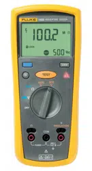
The Fluke model 1507 and model 1503 are
battery-powered insulation testers (the Tester). Although
this manual describes the operation of both Models 1507
and 1503, all illustrations and examples assume use of
model 1507.
These Testers meet IEC 61010 standards. The
IEC 61010-2-030 standard defines three measurement
categories (CAT II to IV) based on the magnitude of
danger from transient impulses. CAT IV Testers are
designed to protect against transients from the primary
supply level (overhead or underground utility service).
The Tester measures or tests the following:
• AC / DC Voltage
• Earth-Bond Resistance
• Insulation Resistance
1.888.610.7664 sales@GlobalTestSupply.com
Fluke-Direct.com

1507/1503
Users Manual
2
Safety Information
Use the Tester only as specified in this manual. Otherwise, the protection provided by the Tester may be impaired. See
Table 1 for a list of symbols used on the Tester and in this manual.
A Warning identifies conditions and procedures that are dangerous to the user. A Caution identifies conditions and
procedures that can cause damage to the Product or the equipment under test.
XW
Warnings
To prevent possible electrical shock, fire, or personal injury:
• Read all safety information before you use the Product.
• Do not alter the Product and use only as specified, or the protection supplied by the Product can be
compromised.
• Carefully read all instructions.
• Do not use the Product around explosive gas, vapor, or in damp or wet environments.
• Comply with local and national safety codes. Use personal protective equipment (approved rubber
gloves, face protection, and flame-resistant clothes) to prevent shock and arc blast injury where
hazardous live conductors are exposed.
• Do not work alone.
• Examine the case before you use the Product. Look for cracks or missing plastic. Carefully look at the
insulation around the terminals.
• Do not use the Product if it is altered or damaged.
• Do not use test leads if they are damaged. Examine the test leads for damaged insulation, exposed
metal, or if the wear indicator shows. Check test lead continuity.
• Do not touch voltages >30 V ac rms, 42 V ac peak, or 60 V dc.
• Do not apply more than the rated voltage, between the terminals or between each terminal and earth ground.
• Use the correct terminals, function, and range for measurements.
1.888.610.7664 sales@GlobalTestSupply.com
Fluke-Direct.com

Insulation Testers
Safety Information
3
• Use Product-approved measurement category (CAT), voltage, and amperage rated accessories (probes,
test leads, and adapters) for all measurements.
• Do not exceed the Measurement Category (CAT) rating of the lowest rated individual component of a
Product, probe, or accessory.
• Do not use in CAT III or CAT IV environments without the protective cap installed on test probe. The
protective cap decreases the exposed probe metal to <4 mm. This decreases the possibility of arc flash
from short circuits.
• Remove all probes, test leads, and accessories that are not necessary for the measurement.
• Keep fingers behind the finger guards on the probes.
• Measure a known voltage first to make sure that the Product operates correctly.
• Always de-energize circuits before you do resistance tests.
• Replace a blown fuse with exact replacement only for continued protection against arc flash.
• Remove the batteries if the Product is not used for an extended period of time, or if stored in
temperatures above 50 °C. If the batteries are not removed, battery leakage may result.
• Replace the batteries when the low battery indicator shows to prevent incorrect measurements.
• Remove all probes, test leads, and accessories before the battery door is opened.
• Replace all batteries with fresh batteries of the same manufacturer and type to prevent battery leakage.
• Repair the Product before use if the battery leaks. Battery leakage may create a shock hazard or
damage the Product.
• The battery door must be closed and locked before you operate the Product.
• Do not operate the Product with covers removed or the case open. Hazardous voltage exposure is
possible.
• Have an approved technician repair the Product.
1.888.610.7664 sales@GlobalTestSupply.com
Fluke-Direct.com
1507/1503
Users Manual
4
Table 1. Symbols
Symbol Description Symbol Description
W
WARNING. RISK OF DANGER.
Earth
X
WARNING. HAZARDOUS VOLTAGE. Risk of
electric shock.
Fuse
Consult user documentation.
T
Double Insulated
Battery
6
WARNING. Do not use in distribution systems
with voltages >660 V.
P
Conforms to European Union directives.
)
Certified by CSA Group to North American safety
standards.
Conforms to relevant Australian Safety and
EMC standards.
Conforms to relevant South Korean EMC
Standards.
Measurement Category II is applicable to test and measuring circuits connected directly to utilization points
(socket outlets and similar points) of the low-voltage MAINS installation.
Measurement Category III is applicable to test and measuring circuits connected to the distribution part of the
building’s low-voltage MAINS installation.
Measurement Category IV is applicable to test and measuring circuits connected at the source of the
building’s low-voltage MAINS installation.
~
This product complies with the WEEE Directive marking requirements. The affixed label indicates that you
must not discard this electrical/electronic product in domestic household waste. Product Category: With
reference to the equipment types in the WEEE Directive Annex I, this product is classed as category 9
"Monitoring and Control Instrumentation" product. Do not dispose of this product as unsorted municipal waste.
1.888.610.7664 sales@GlobalTestSupply.com
Fluke-Direct.com
Insulation Testers
Unsafe Voltage
5
Unsafe Voltage
To alert you to the presence of a potentially hazardous
voltage, when the Tester detects a voltage ≥ 30 V in
insulation test, ≥2 V in resistance, or a voltage overload
(), the symbol is displayed.
Battery Saver
(Sleep Mode)
The Tester enters the “Sleep mode” and blanks the
display if there is no function change or button press for
10 minutes. This is done to conserve battery power. To
resume operation, turn the rotary switch to OFF and then
turn to any function.
The 10-minute timer is disabled during any insulation
resistance or earth bond resistance measurement. The
time period starts immediately following any
measurement.
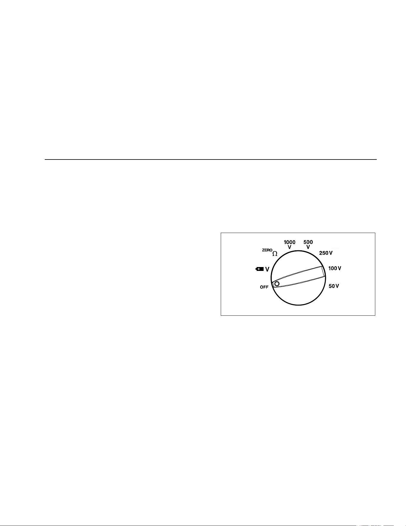
Rotary Switch Positions
Turn the Tester on by selecting any measurement
function. The Tester presents a standard display for that
function (range, measurement units, modifiers, etc.). Use
the blue button to select any rotary switch alternate
functions (labelled with blue letters). Rotary switch
selections are shown in Figure 1 and described in Table 2.
bbw03f.emf
Figure 1. Rotary Switch
1.888.610.7664 sales@GlobalTestSupply.com
Fluke-Direct.com
1507/1503
Users Manual
6
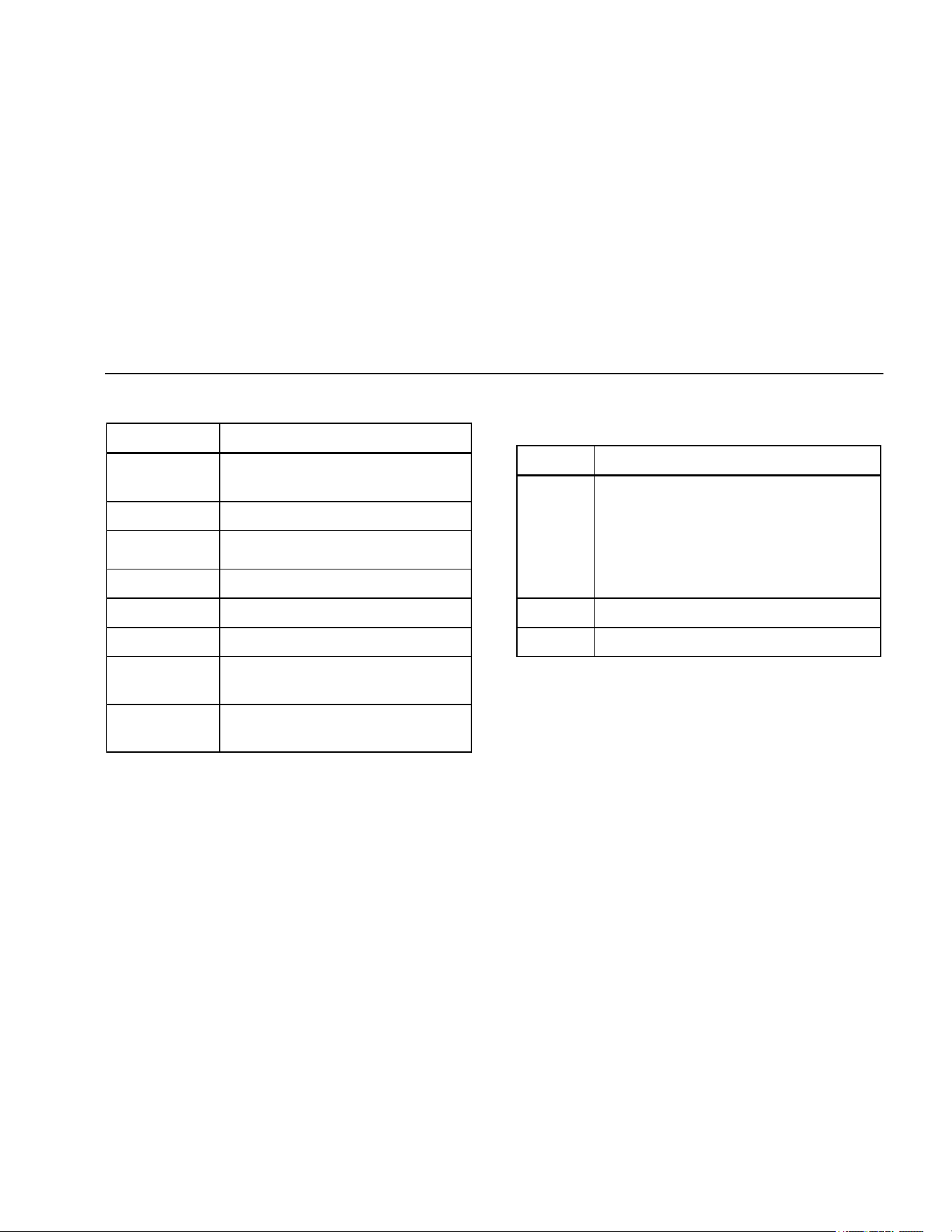
Table 2. Rotary Switch Selections
Switch
Position
Measurement Function
OFF
Turn off the Tester.
AC or DC voltage from 0.1 V to 600.0 V.
Ohms from 0.01 Ω to 20.00 kΩ.
250V
100V
50V
Ohms from 0.01 MΩ to 10.0 GΩ for the
Model 1507 and 0.01 to 2000 MΩ for the
Model 1503.
Performs insulation tests with 50, 100, 250,
500 and 1000 V dc source on the 1507 or
500 and 1000 V dc source on the 1503.
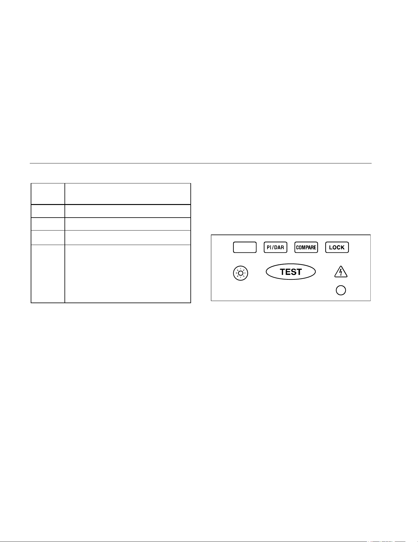
Buttons and Indicators
Use the buttons to activate features that augment the
function selected with the rotary switch. There are also two
indicators on the front of the Tester which light up when
active. The buttons and indicators are shown in Figure 2
and described in Table 3.
bbw02f.emf
Figure 2. Buttons and Indicators
1.888.610.7664 sales@GlobalTestSupply.com
Fluke-Direct.com
Insulation Testers
Buttons and Indicators
7
Table 3. Buttons and Indicators
Button/
Indicator
Description
Press the blue button to select alternate
measurement functions.
Press to configure the Tester for a
polarization index or dielectric absorption
ratio test. The test will start when you press
the button.
Sets a pass/fail limit for insulation tests.
Test lock. When pressed before the
button, the test remains active until you
press the lock or test button again to
release the lock.
Turns the backlight on and off. The
backlight goes off after 2 minutes.
Button/
Indicator
Description
Initiates an insulation test when the rotary
switch is in
INSULATION position. Causes
the Tester to source (output) a high voltage
and measure insulation resistance.
Initiates a resistance test when the rotary
switch is in the ohms position.
Unsafe voltage warning. Indicates 30 V or
greater (ac or dc depending on the rotary
switch position) is detected on the input.
Also appears when the display shows in
the switch positions, and when
appears on the display. The also appears
when insulation test is active.
Pass indicator. Indicates when the
insulation resistance measurement is
greater than the selected compare limit.
1.888.610.7664 sales@GlobalTestSupply.com
Fluke-Direct.com
1507/1503
Users Manual
8
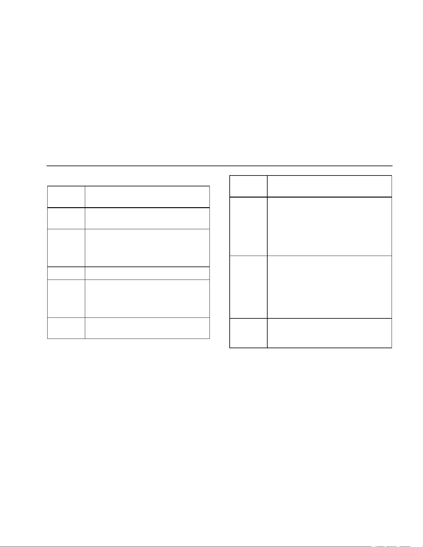
Understanding the Display
Display indicators are shown in Figure 3 and described in
Table 4. Error messages that may appear on the display
are described in Table 5.
bbw01f.emf
Figure 3. Display Indicators
Table 4. Display Indicators
Indicator Description
Indicates an insulation or resistance
test is locked on.
−
Minus or greater than symbols
Unsafe voltage warning.
Low battery. Indicates when it is
time to replace the battery. When
is on, the backlight button is
disabled to conserve battery life.
XW Warning
To avoid false readings, which
could lead to possible electric
shock or personal injury,
replace the battery as soon as
the low battery indicator
appears.
1.888.610.7664 sales@GlobalTestSupply.com
Fluke-Direct.com
Insulation Testers
Understanding the Display
9
Table 4 Display Indicators (cont.)
Indicator Description
Polarization index or dielectric
absorption ratio test is selected.
ZERO Ohms lead zero is active.
VAC, VDC, Ω,
kΩ, MΩ, GΩ
Measurement units
Primary display
V
DC
Volts
Secondary display
COMPARE Indicates selected pass/fail compare
value.
Insulation test indicator. Appears when
insulation test voltage is present.
Table 5. Error Messages
Message Description
Appears on the primary display and
indicates that the battery is too low for
reliable operation. The Tester will not
operate at all until the battery is replaced.
The also appears when is on the
primary display.
> Indicates an out of range value.
Invalid calibration data. Calibrate the Tester.
1.888.610.7664 sales@GlobalTestSupply.com
Fluke-Direct.com
1507/1503
Users Manual
10
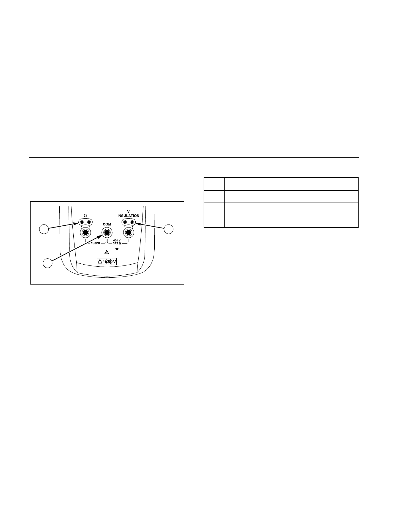
Input Terminals
Input terminals are shown in Figure 4 and described in
Table 6.
1 3
2
bbw08f.emf
Figure 4. Input Terminals
Table 6. Input Terminal Descriptions
.
Item Description
Input terminal for resistance measurement.
Common (return) terminal for all measurements.
Input terminal for volts or insulation test.
Power-Up Options
Holding a button down while turning the Tester on
activates a power-up option. Power-up options allow you
to use additional features and functions of the Tester. To
select a power-up option, hold down the appropriate
button indicated while turning the Tester from OFF to any
switch position. Power-up options are cancelled when the
Tester is turned OFF. Power-up options are described in
Table 7.
1.888.610.7664 sales@GlobalTestSupply.com
Fluke-Direct.com

Insulation Testers
Making Measurements
11
Table 7. Power-Up Options
Button Description
switch position turns on all LCD
segments.
switch position displays the software
version number.
switch position displays the model
number.
Starts the Calibration mode. The Tester
displays and enters Calibration mode
when the button is released.
Note
Power Up options are active when the button is
pressed.
Making Measurements
The figures on the following pages show how to make
measurements.
When connecting the test leads to the circuit or device,
connect the common (COM) test lead before connecting
the live lead; when removing the test leads, remove the
live lead before removing the common test lead.
XW Warning
To avoid electric shock, injury, or damage to
the Tester, disconnect circuit power and
discharge all high-voltage capacitors before
testing.
1.888.610.7664 sales@GlobalTestSupply.com
Fluke-Direct.com
1507/1503
Users Manual
12
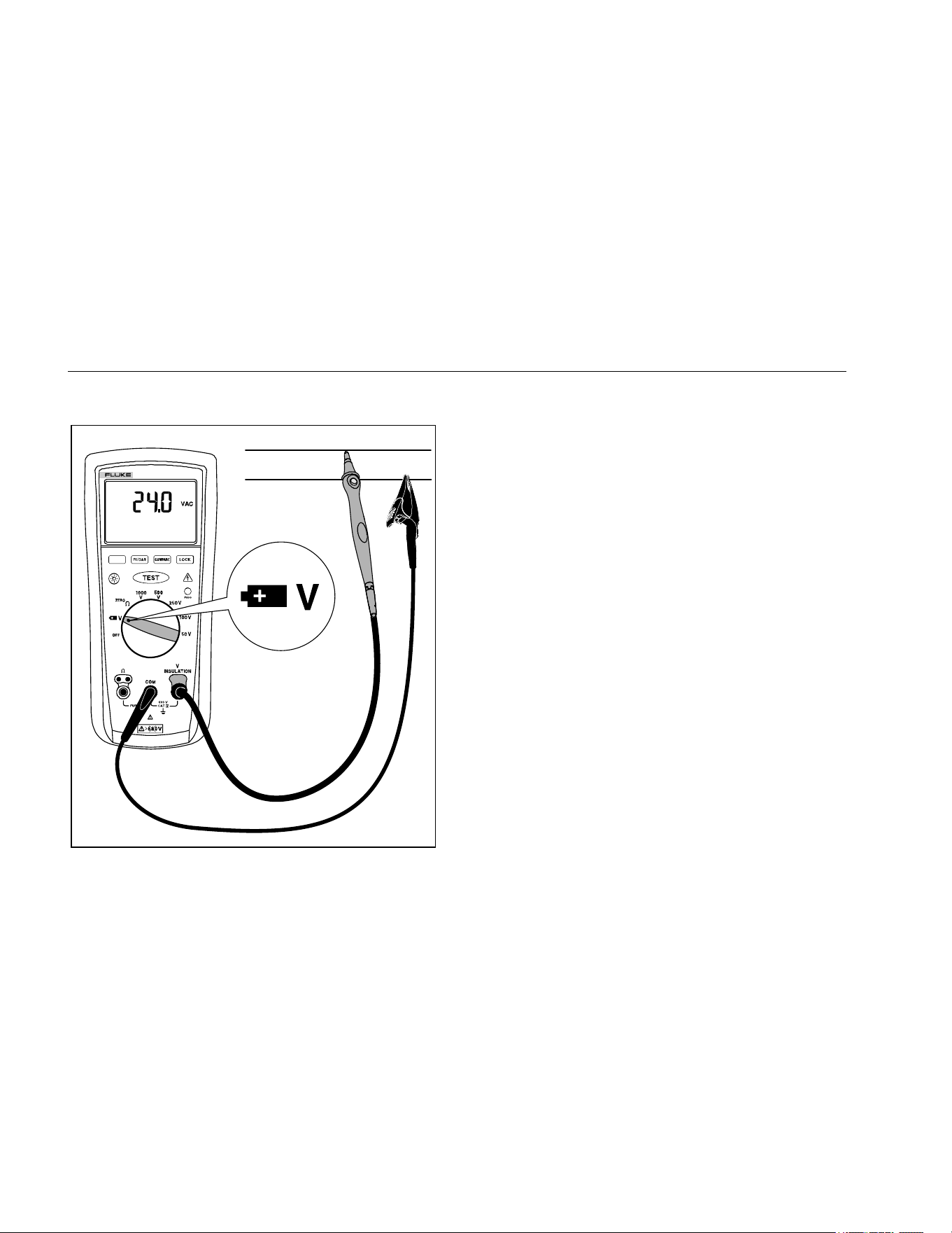
Measuring Volts
INSULATION TESTER
1507
bbw09f.emf
Figure 5. Measuring Volts
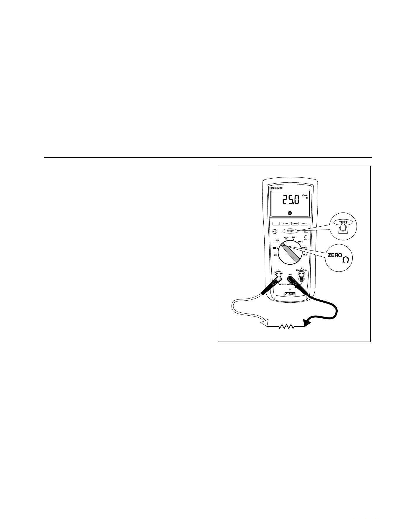
Measuring Earth-Bond Resistance
Resistance tests should only be performed on
de-energized circuits. Check the fuse before testing. See
Testing the Fuse later in this manual. Connecting to an
energized circuit while the test is active will blow the fuse.
Note
Measurements can be adversely affected by
impedances of additional operating circuits
connected in parallel or by transient currents.
To measure resistance:
1. Insert test probes in the Ω and
COM input terminals.
See Figure 6.
2. Turn the rotary switch to the position.
3. Short the ends of the probes together, press the blue
button and wait until dashes appear on the display.
The Tester measures the probe resistance, stores the
reading in memory, and subtracts it from readings.
The probe resistance reading is saved even when the
Tester is turned off. If the probe resistance is >2 Ω,
the resistance will not be saved.
4. Connect the probes to the circuit to be measured. The
Tester automatically detects if the circuit is energized.
1.888.610.7664 sales@GlobalTestSupply.com
Fluke-Direct.com
Insulation Testers
Making Measurements
13
• The primary display shows ---- until you press the
button and a valid resistance reading is
obtained.
• The high voltage symbol (Y) along with a primary
display of >2 V warns if voltage greater than 2 V
ac or dc is present. In this condition, the test is
inhibited. Disconnect the Tester and remove
power before proceeding.
• If the Tester chirps when you press the
button, the test is inhibited because voltage is
present at the probes.
5. Push and hold the button to start the test. The
icon appears on the lower portion of the display
until you release the button. The resistance
reading appears on the primary display until a new
test is started or a different function or range is
selected.
When resistance is higher than the maximum display
range, the Tester displays the > symbol and the
maximum resistance for the range.
.
INSULATION TESTER
1507
bbw04f.emf
Figure 6. Measuring Earth-Bond Resistance
1.888.610.7664 sales@GlobalTestSupply.com
Fluke-Direct.com

1507/1503
Users Manual
14
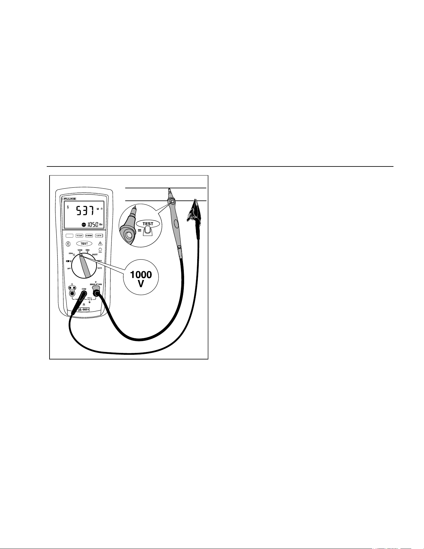
Measuring Insulation Resistance
Insulation tests should only be performed on de-energized
circuits. To measure insulation resistance set up the
Tester as shown in Figure 7 and follow the steps below:
1. Insert test probes in the V and COM input terminals.
2. Turn the rotary switch to the desired test voltage.
3. Connect the probes to the circuit to be measured. The
Tester automatically detects if the circuit is energized.
• The primary display shows until you press
and a valid insulation resistance reading
is obtained.
• The high voltage symbol () along with a primary
display of >30 V warns if voltage more than 30 V
ac or dc is present. In this condition, the test is
inhibited. Disconnect the Tester and remove
power before proceeding.
4. Push and hold to start the test. The secondary
display shows the test voltage applied to the circuit
under test. The high voltage symbol () along with a
primary display showing the resistance in MΩ or GΩ
appears. The
icon appears on the lower portion of
the display until is released.
When resistance is higher than the maximum display
range, the Tester displays the symbol and the
maximum resistance for the range.
5. Keep the probes on the test points and release the
button. The circuit under test then discharges
through the Tester. The resistance reading appears
on the primary display until a new test is started or a
different function or range is selected or >30 V is
detected.
1.888.610.7664 sales@GlobalTestSupply.com
Fluke-Direct.com
Insulation Testers
Measuring Polarization Index and Dielectric Absorption Ratios (Model 1507)
15
INSULATION TESTER
1507
bbw05f.emf
Figure 7. Measuring Insulation Resistance
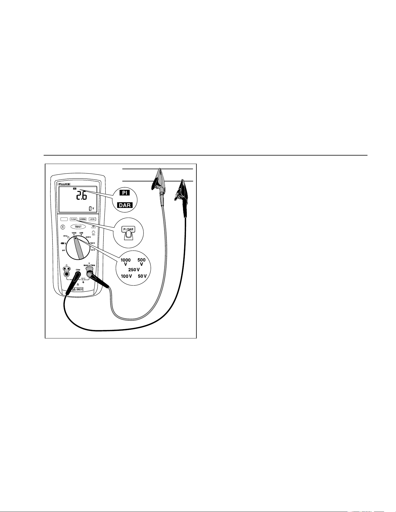
Measuring Polarization Index and
Dielectric Absorption Ratios (Model
1507)
Polarization Index (PI) is the ratio of the 10-minute
insulation resistance to the 1 minute insulation resistance.
Dielectric Absorption Ratio (DAR) is the ratio of the
1-minute insulation resistance to the 30 second insulation
resistance.
Insulation tests should only be performed on de-energized
circuits. To measure the polarization index or dielectric
absorption ratio:
1. Insert test probes in the
INSULATION and COM input
terminals.
Note
Because of the time required to perform the PI
and DAR tests, use of test clips is recommended.
2. Turn the rotary switch to the desired test voltage
position.
3. Press the button to select polarization index or
dielectric absorption ratio.
1.888.610.7664 sales@GlobalTestSupply.com
Fluke-Direct.com

1507/1503
Users Manual
16
4. Connect the probes to the circuit to be measured. The
Tester automatically detects if the circuit is energized.
• The primary display shows ---- until you press the
button and a valid resistance reading is
obtained.
• The high voltage symbol () along with a primary
display of >30 V warns if voltage greater that
30 V ac or dc is present. If high voltage is
present, the test is inhibited.
5. Press and release to start the test. During
testing, the secondary display shows the test voltage
applied to the circuit under test. The high voltage
symbol () along with a primary display showing the
resistance in MΩ or GΩ. The icon appears on the
lower portion of the display until the test is finished.
When the test is completed, the PI or DAR value is
displayed on the primary display. The circuit under
test will automatically be discharged through the
Tester. If either value used to calculate PI or DAR
was greater than the maximum display range, or the
1-minute value was greater than 5000 MΩ, the
primary display will show .
• When resistance is higher than the maximum
display range, the Tester displays the > symbol
and the maximum resistance for the range.
• To interrupt a PI or DAR test before it is
completed, momentarily press . When you
release , the circuit under test will
automatically be discharged through the Tester.
1.888.610.7664 sales@GlobalTestSupply.com
Fluke-Direct.com
Insulation Testers
Using the Compare Function (Model 1507)
17
INSULATION TESTER
1507
or
bbw10f.emf
Figure 8. Measuring Polarization Index and Dielectric
Absorption Ratios
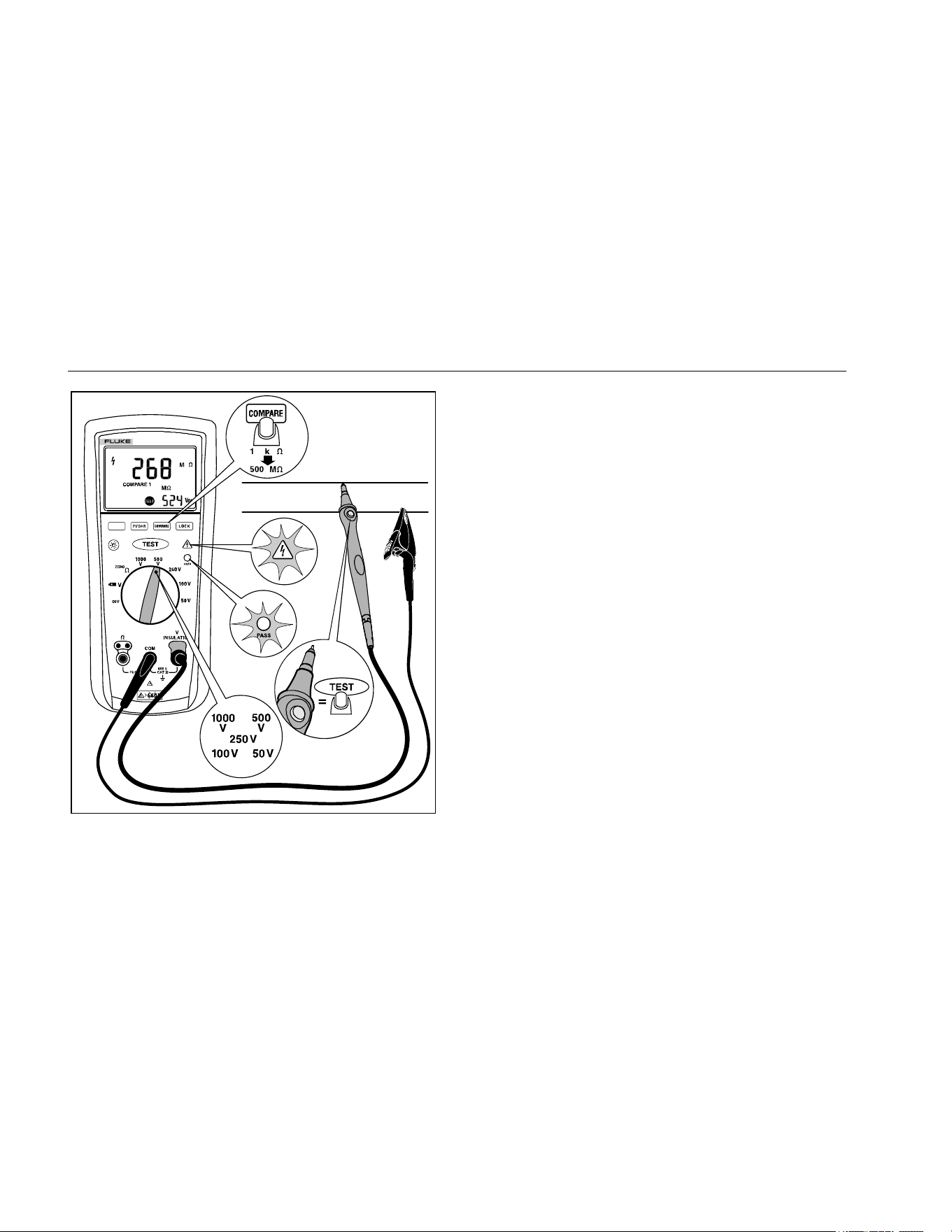
Using the Compare Function (Model
1507)
Use the Compare function to set a pass/fail compare level
for the insulation measurements. To use the Compare
function:
1. Press the button to select the desired compare
value. You can choose from 100 kΩ, 200 kΩ, 500 kΩ,
1 MΩ, 2 MΩ, 5 MΩ, 10 MΩ, 20 MΩ, 50 MΩ, 100 MΩ,
200 MΩ, and 500 MΩ.
2. Perform insulation tests as described earlier in this
manual.
3. The green pass indicator will appear if the measured
value is greater than the selected value.
4. Press and hold the button for 1 second to
disable the Compare function. The pass indicator will
turn off when you start a new test or choose a new
compare value.
1.888.610.7664 sales@GlobalTestSupply.com
Fluke-Direct.com
1507/1503
Users Manual
18
INSULATION TESTER
1507
bbw11f.emf
Figure 9. Using the Compare Function
Cleaning
Periodically wipe the case with a damp cloth and mild
detergent. Do not use abrasives or solvents. Dirt or
moisture in the terminals can affect readings. Allow time
for drying before using the Tester.
Testing the Batteries
The Tester continuously monitors battery voltage. If the
low battery icon () appears on the display, there is
minimal battery life left. To test the batteries:
1. Turn the rotary switch to the position with no
probes inserted.
2. Press the blue button to initiate the fully loaded
battery test. The voltage function displays clear and
the measured battery voltage is shown in the primary
display for 2 seconds, the voltage display then
returns.
1.888.610.7664 sales@GlobalTestSupply.com
Fluke-Direct.com
Insulation Testers
Testing the Fuse
19
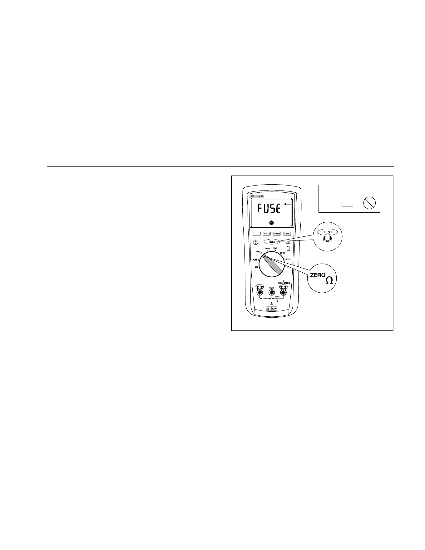
Testing the Fuse
XW Warning
To avoid electrical shock or injury, remove
the test leads and any input signals before
replacing the fuse.
Test the fuse as described below and shown in Figure 10.
Replace the fuse as shown in Figure 11.
1. Turn the rotary switch to the position.
2. Press and hold . If the display reading is ,
the fuse is bad and should be replaced.
INSULATION TESTER
1507
315 mA
Fuse
OK
bbw06f.emf
Figure 10. Testing the Fuse
1.888.610.7664 sales@GlobalTestSupply.com
Fluke-Direct.com
1507/1503
Users Manual
20
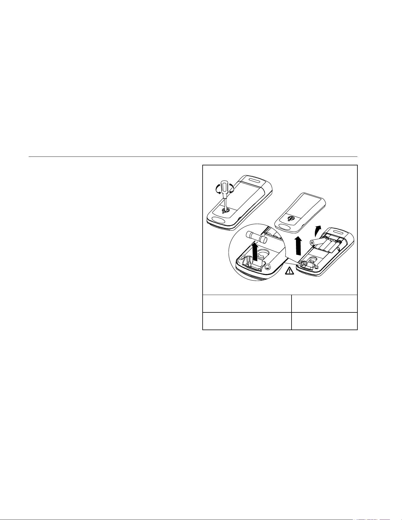
Replacing the Batteries and Fuse
Replace the fuse and batteries as shown in Figure 11.
Follow the steps below to replace the batteries.
XW Warning
To avoid shock, injury, or damage to the
Tester:
• To avoid false readings, which could lead
to possible electric shock or personal
injury, replace the batteries as soon as
the battery indicator () appears.
• Use ONLY fuses with the amperage,
interrupt, voltage, and speed ratings
specified.
• Turn the rotary switch to OFF and remove
the test leads from the terminals.
1. Remove the battery door by using a standard
screwdriver to turn the battery door lock until the
unlock symbol aligns with the arrow.
2. Remove and replace the batteries.
3. Replace the battery door and secure by turning the
battery door lock until the lock symbol aligns with the
arrow.
F315 mA 1000 V
Min interrupt rating
10000 A
bbw15f.emf
Fuse, Fast, 315 mA, 1000 V,
Min Interrupt Rating 10 000 A
Fluke PN 2279339
Battery, 1.5 V AA Alkaline,
NEDA 15A, IEC LR6
Fluke PN 376756
Figure 11. Replacing the Fuse and Battery
1.888.610.7664 sales@GlobalTestSupply.com
Fluke-Direct.com

Insulation Testers
Specifications
21
Specifications
Maximum Voltage between any
Terminal and Earth .................................................. 600 V
Storage Temperature .............................................. -40 °C to 60 °C
Operating Temperature ........................................... -20 °C to 55 °C
Temperature Coefficient .......................................... 0.05 x (specified accuracy) per °C for temperatures <18 °C or >28 °C
Relative Humidity .................................................... Noncondensing
0 % to 95 % @ 10 °C to 30 °C
0 % to 75 % @ 30 °C to 40 °C
0 % to 40 % @ 40 °C to 55 °C
Batteries .................................................................. Four AA batteries (IEC LR6)
Battery Life .............................................................. Insulation test use: Tester can perform at least 1000 insulation tests with fresh alkaline
batteries at room temperature. These are standard tests of 1000 V into 1 MΩ with a duty
cycle of 5 seconds on and 25 seconds off. Resistance Measurements: Tester can perform
at least 2500 earth-bond resistance measurements with fresh alkaline batteries at room
temperature. These are standard tests of 1 Ω with a duty cycle of 5 seconds on and 25
seconds off.
Size ......................................................................... 5.0 cm H x 10.0 cm W x 20.3 cm L (1.97 in H x 3.94 in W x 8.00 in L)
Weight ..................................................................... 550 g (1.2 lb)
Ingress Protection Rating ........................................ IEC 60529: IP40
Altitude
Operating ............................................................. 2000 m
Storage ................................................................ 12 000 m
Over-Range Capability ............................................ 110 % of range
1.888.610.7664 sales@GlobalTestSupply.com
Fluke-Direct.com

1507/1503
Users Manual
22
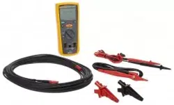
Accessories ............................................................. TL224 Leads
TP74 Probes with Protective Caps
Alligator Clips PN 1958654 (red) and PN 1958646 (black)
Holster
Remote Probe with Protective Cap
Safety
General ............................................................... IEC 61010-1: Pollution Degree 2
Measurement ...................................................... IEC 61010-2-030; CAT IV 600 V IEC 61010-031, IEC 61557-1, IEC 61557-2,
IEC 61557-4, IEC 61557-10
Electromagnetic Compatibility (EMC)
International ........................................................ IEC 61326-1: Portable Electromagnetic Environment
CISPR 11: Group 1, Class A
Group 1: Equipment has intentionally generated and/or uses conductively-coupled radio frequency energy that is necessary for the
internal function of the equipment itself.
Class A: Equipment is suitable for use in all establishments other than domestic and those directly connected to a low-voltage power
supply network that supplies buildings used for domestic purposes. There may be potential difficulties in ensuring electromagnetic
compatibility in other environments due to conducted and radiated disturbances.
Korea (KCC) ........................................................ Class A Equipment (Industrial Broadcasting & Communication Equipment)
Class A: Equipment meets requirements for industrial electromagnetic wave equipment and the seller or user should take notice of it.
This equipment is intended for use in business environments and not to be used in homes.
USA (FCC) .......................................................... 47 CFR 15 subpart B. This product is considered an exempt device per clause 15.103.
1.888.610.7664 sales@GlobalTestSupply.com
Fluke-Direct.com
Insulation Testers
Specifications
23
AC/DC Voltage Measurement
Accuracy
Range Resolution
50 Hz to 400 Hz
± (% of Rdg + Digits)
600.0 V 0.1 V + (2 % + 3)
Input Impedance .................................................. 3 MΩ (nominal), <100 pF
Common Mode Rejection Ratio
(1 kΩ unbalanced) ............................................... >60 dB at dc, 50 Hz or 60 Hz
Overload Protection ............................................. 600 V rms or dc
1.888.610.7664 sales@GlobalTestSupply.com
Fluke-Direct.com
1507/1503
Users Manual
24
Earth-bond Resistance Measurement
Range Resolution
Accuracy
[1]
+ (% of Rdg + Digits)
20.00 Ω 0.01 Ω
+ (1.5 % + 3)
200.0 Ω 0.1 Ω
2000 Ω 1 Ω
20.00 kΩ 0.01 kΩ
[1] Accuracies apply from 0 to 100% of range.
Overload Protection ............................................ 2 V rms or dc
Open Circuit Test Voltage ................................... >4.0 V, <8 V
Short Circuit Current ........................................... >200.0 mA
Insulation Specifications
Measurement Range ........................................... 0.01 MΩ to 10 GΩ model 1507, 0.01 MΩ to 2000 MΩ model 1503
Test Voltages ...................................................... 50, 100, 250, 500, 1000 V dc model 1507, 500 and 1000 V dc model 1503
Test Voltage Accuracy ........................................ +20 %, -0 %
Short-Circuit Test Current ................................... 1 mA nominal
Auto Discharge .................................................... Discharge time <0.5 second for C = 1 μF or less
Live Circuit Detection: ......................................... Inhibit test if terminal voltage >30 V prior to initialization of test.
Maximum Capacitive Load .................................. Operable with up to 1 μF load.
1.888.610.7664 sales@GlobalTestSupply.com
Fluke-Direct.com
Insulation Testers
Specifications
25
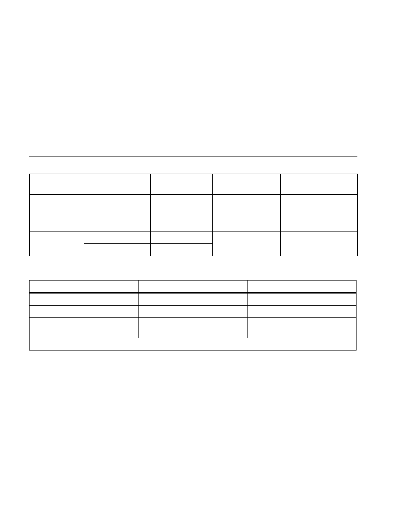
Model 1507
Output Voltage Display Range Resolution Test Current
Accuracy
± (% of Rdg + Digits)
50 V dc
(0 % to + 20 %)
0.01 to 20.00 MΩ 0.01 MΩ
1 mA @ 50 kΩ ± (3 % + 5)
20.0 to 50.0 MΩ 0.1 MΩ
100 V dc
(0 % to + 20 %)
0.01 to 20.00 MΩ 0.01 MΩ
1 mA @ 100 kΩ ± (3 % + 5)
20.0 to 100.0 MΩ 0.1 MΩ
250 V dc
(0 % to + 20 %)
0.01 to 20.00 MΩ 0.01 MΩ
1 mA @ 250 kΩ ± (1.5 % + 5)
20.0 to 200.0 MΩ 0.1 MΩ
500 V dc
(0 % to + 20 %)
0.01 to 20.00 MΩ 0.01 MΩ
1 mA @ 500 kΩ ± (1.5 % + 5) 20.0 to 200.0 MΩ 0.1 MΩ
200 to 500 MΩ 1 MΩ
1000 V dc
(0 % to + 20 %)
0.1 to 200.0 MΩ 0.1 MΩ
1 mA @ 1 MΩ
± (1.5 % + 5)
200 to 2000 MΩ 1 MΩ
2.0 to 10.0 GΩ 0.1 GΩ ± (10 % + 3)
1.888.610.7664 sales@GlobalTestSupply.com
Fluke-Direct.com
1507/1503
Users Manual
26
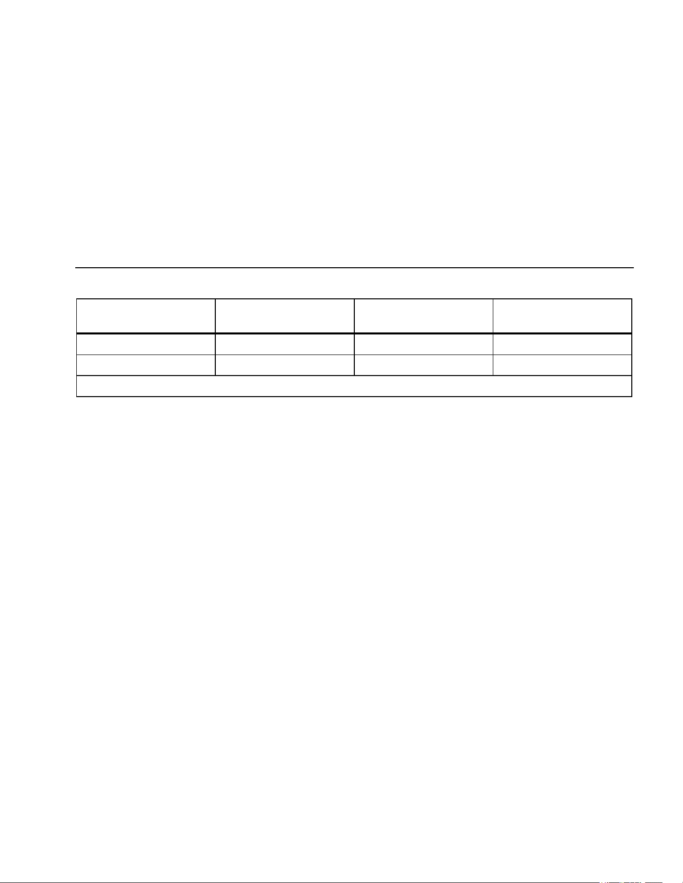
Model 1503
Output Voltage Display Range Resolution Test Current
Accuracy
± (% of Rdg + Digits)
500 V dc
(0 % to + 20 %)
0.01 to 20.00 MΩ 0.01 MΩ
1 mA @ 500 kΩ ± (2.0 % + 5)
20.0 to 200.0 MΩ 0.1 MΩ
200 to 500 MΩ 1 MΩ
1000 V dc
0 % to + 20 %)
0.1 to 200.0 MΩ 0.1 MΩ
1 mA @ 1 MΩ ± (2.0 % + 5)
200 to 2000 MΩ 1 MΩ
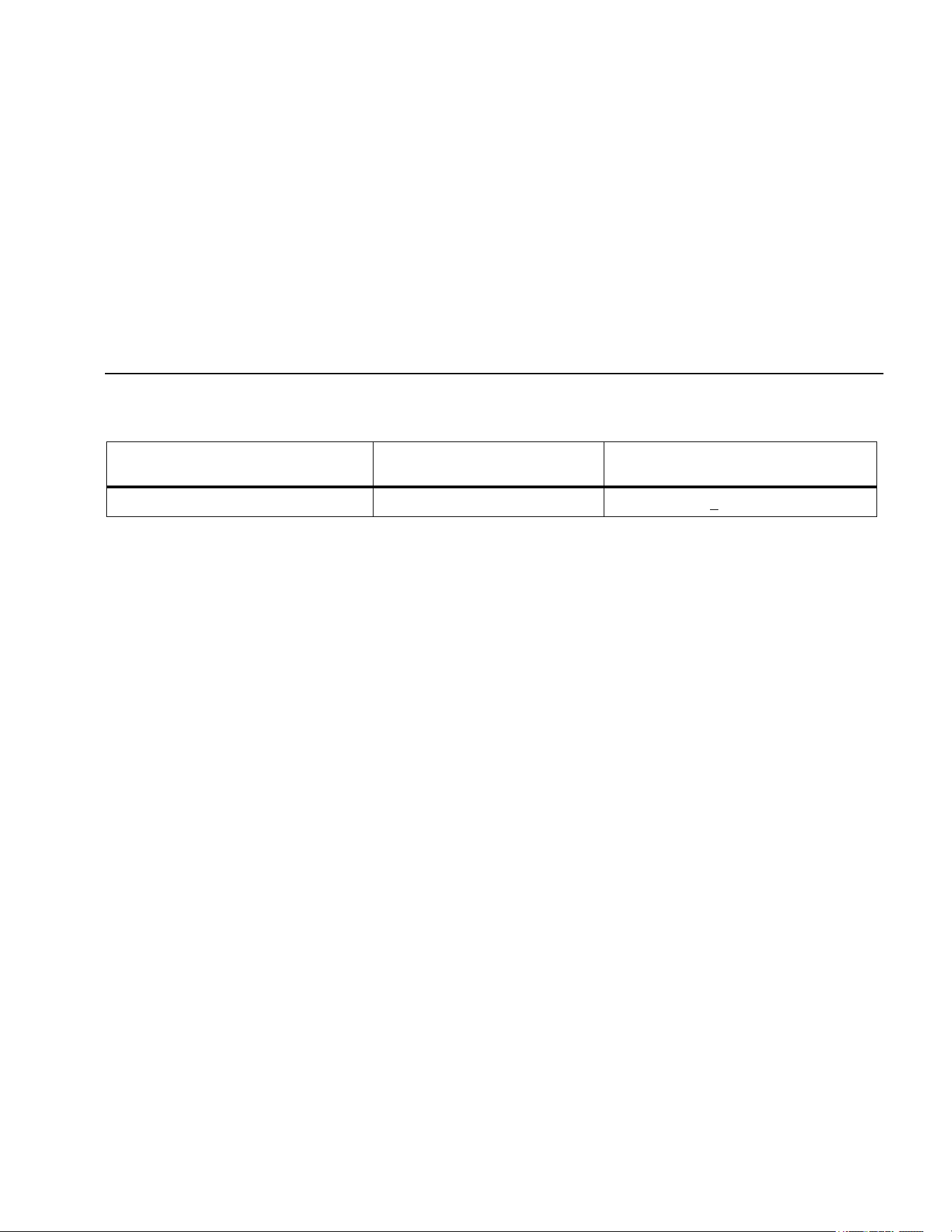
IEC 61557 Specification
The following tables are a requirement for European labeling.
Measurement Intrinsic Uncertainty Operating Uncertainty
[1]
Volts ± (2.0 % + 3) 30 %
Earth-Bond Resistance ± (1.5 % + 3) 30 %
Insulation Resistance
Depends on test voltage and range.
See Insulation Test specifications.
30 %
[1] This specification comes from the standard and indicates the maximum amount allowable by the standard.
1.888.610.7664 sales@GlobalTestSupply.com
Fluke-Direct.com
Insulation Testers
Specifications
27
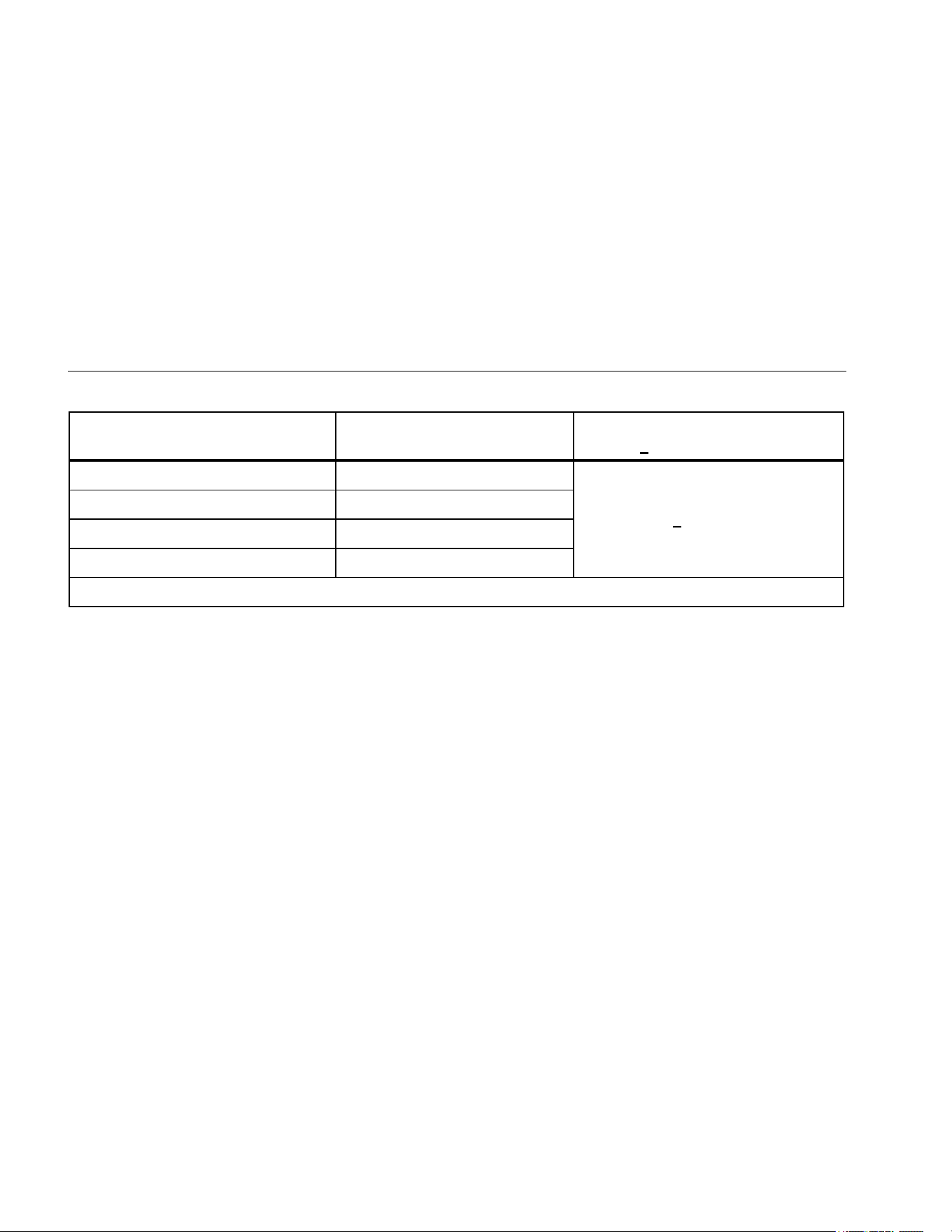
IEC 61557 Influence Variables and Uncertainties
Earth-Bond Resistance
Influence Variable
Designation per EN61557
Uncertainty for Insulation
Resistance
[1]
Uncertainty for Earth-Bond
Resistance
[1]
Supply Voltage E2 5 % 5 %
Temperature E3 5 % 5 %
[1] Specification confidence level 99 %.
1.888.610.7664 sales@GlobalTestSupply.com
Fluke-Direct.com
1507/1503
Users Manual
28
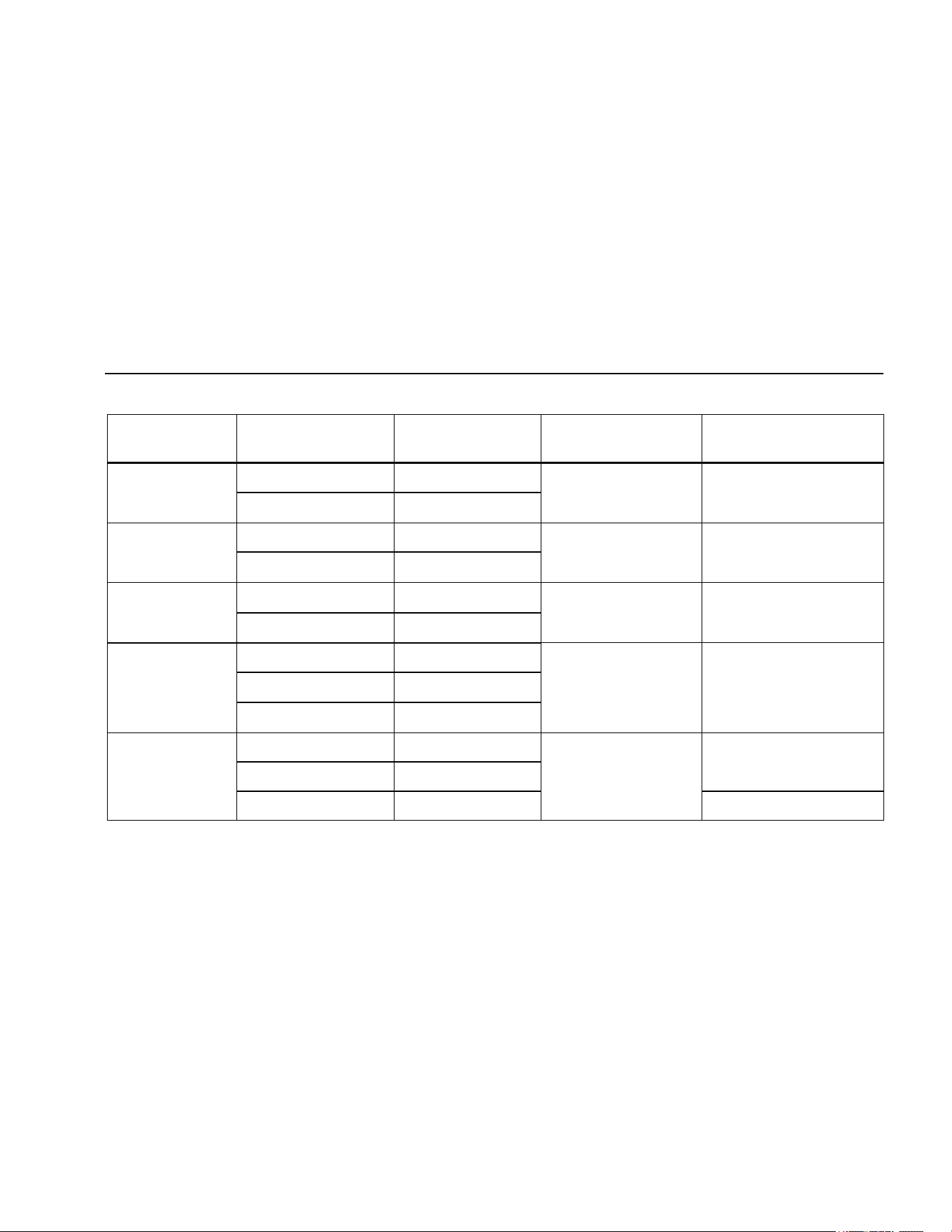
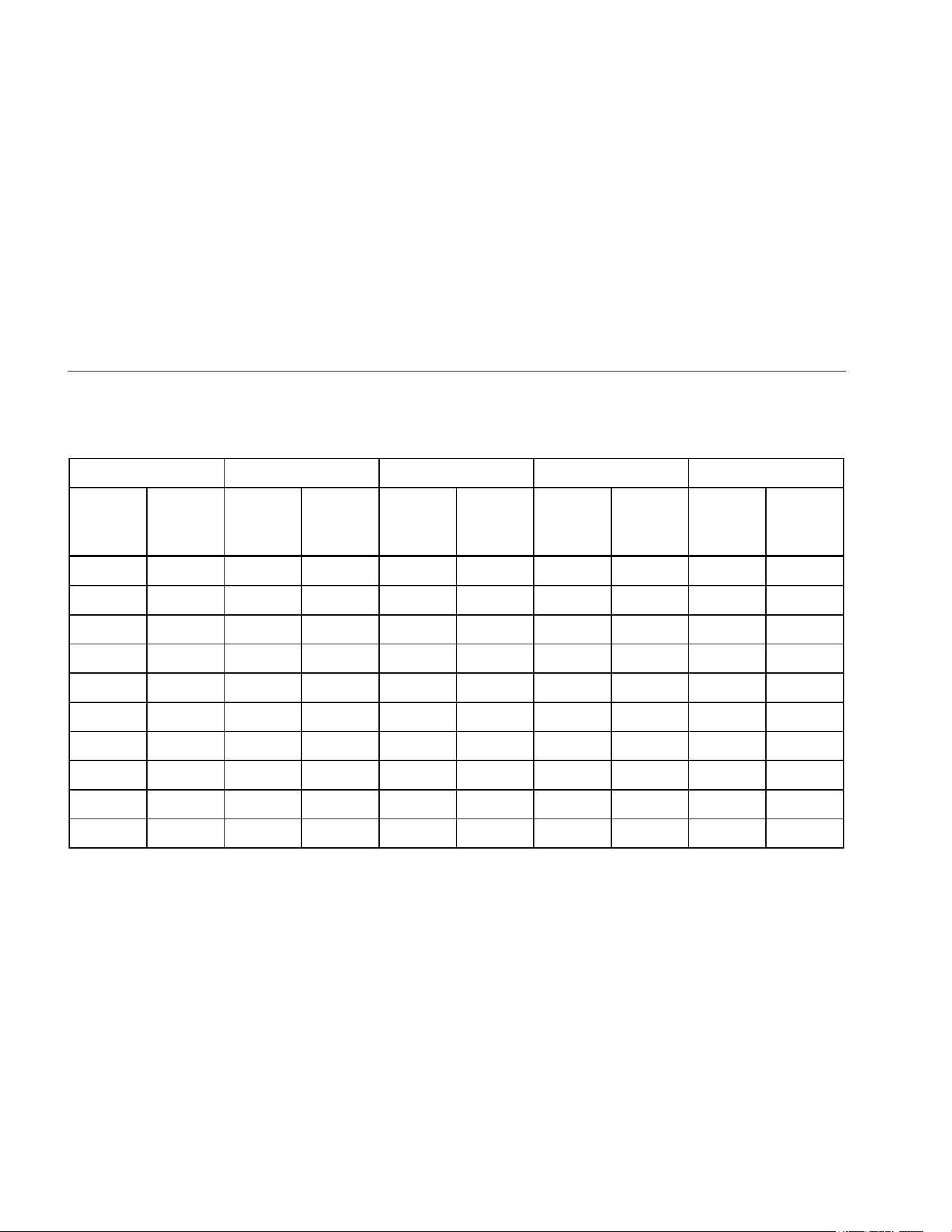
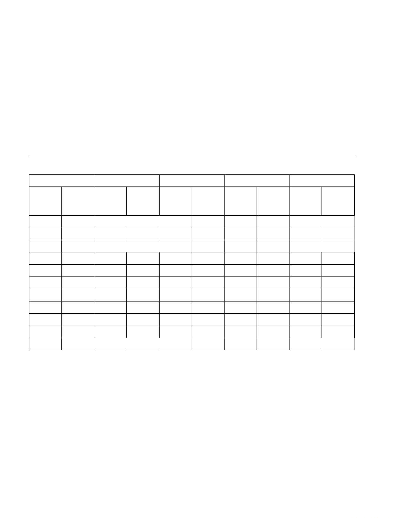
The following tables can be used to determine the maximum or minimum display values considering maximum instrument
operating error per IEC 61557.
Insulation Resistance Maximum and Minimum Display Values
50 V 100 V 250 V 500 V 1000 V
Limit
Value
Minimum
Display
Value
Limit
Value
Minimum
Display
Value
Limit
Value
Minimum
Display
Value
Limit
Value
Minimum
Display
Value
Limit
Value
Minimum
Display
Value
0.05 0.07 0.05 0.07 0.05 0.07 0.05 0.07
0.06 0.08 0.06 0.08 0.06 0.08 0.06 0.08
0.07 0.09 0.07 0.09 0.07 0.09 0.07 0.09
0.08 0.10 0.08 0.10 0.08 0.10 0.08 0.10
0.09 0.12 0.09 0.12 0.09 0.12 0.09 0.12
0.1 0.13 0.1 0.13 0.1 0.13 0.1 0.13 0.1 0.1
0.2 0.26 0.2 0.26 0.2 0.26 0.2 0.26 0.2 0.3
0.3 0.39 0.3 0.39 0.3 0.39 0.3 0.39 0.3 0.4
0.4 0.52 0.4 0.52 0.4 0.52 0.4 0.52 0.4 0.5
0.5 0.65 0.5 0.65 0.5 0.65 0.5 0.65 0.5 0.7
1.888.610.7664 sales@GlobalTestSupply.com
Fluke-Direct.com
Insulation Testers
Specifications
29
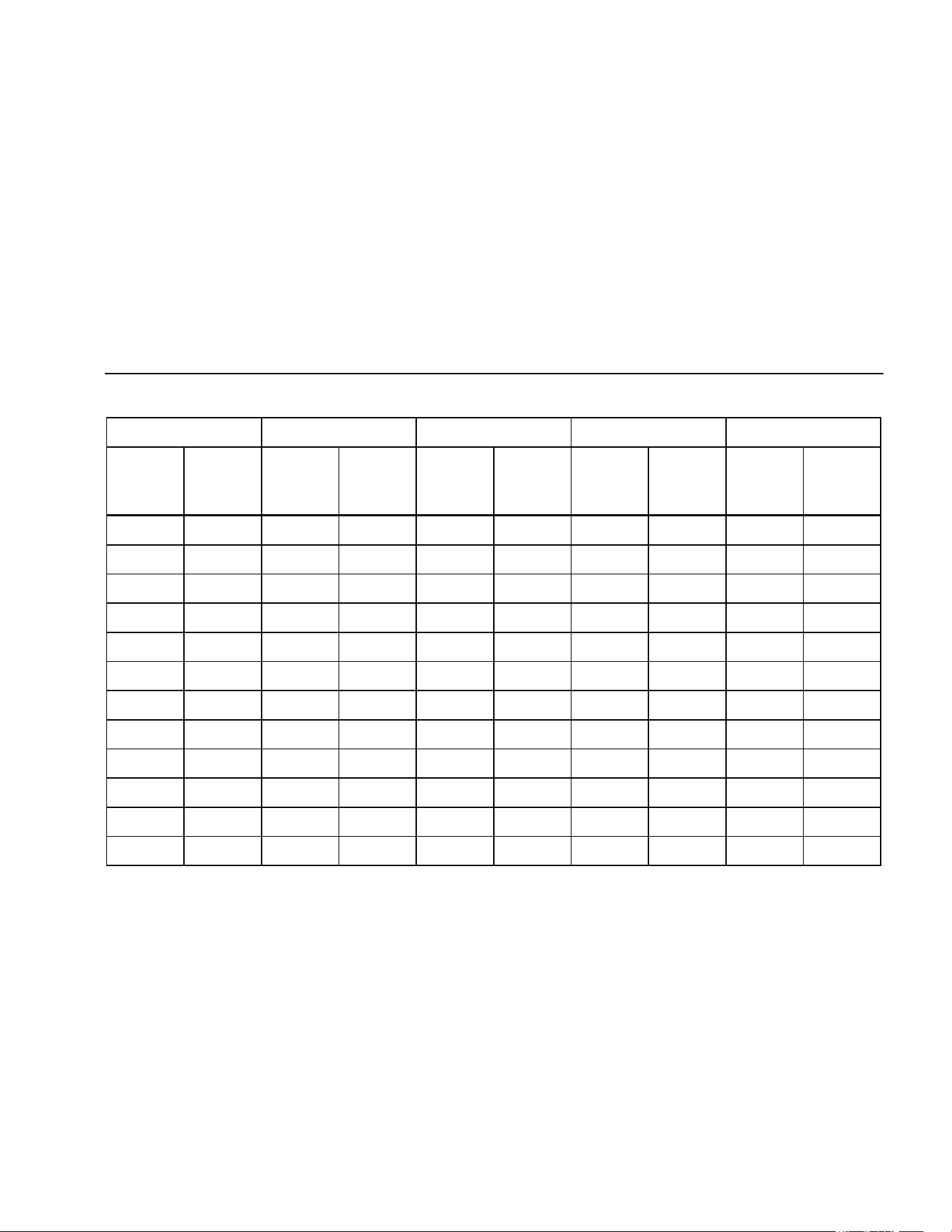
Insulation Resistance Maximum and Minimum Display Values (cont.)
50 V 100 V 250 V 500 V 1000 V
Limit
Value
Minimum
Display
Value
Limit
Value
Minimum
Display
Value
Limit
Value
Minimum
Display
Value
Limit
Value
Minimum
Display
Value
Limit
Value
Minimum
Display
Value
0.6 0.78 0.6 0.78 0.6 0.78 0.6 0.78 0.6 0.8
0.7 0.91 0.7 0.91 0.7 0.91 0.7 0.91 0.7 0.9
0.8 1.04 0.8 1.04 0.8 1.04 0.8 1.04 0.8 1.0
0.9 1.17 0.9 1.17 0.9 1.17 0.9 1.17 0.9 1.2
1.0 1.30 1.0 1.30 1.0 1.30 1.0 1.30 1.0 1.3
2.0 2.60 2.0 2.60 2.0 2.60 2.0 2.60 2.0 2.6
3.0 3.90 3.0 3.90 3.0 3.90 3.0 3.90 3.0 3.9
4.0 5.20 4.0 5.20 4.0 5.20 4.0 5.20 4.0 5.2
5.0 6.50 5.0 6.50 5.0 6.50 5.0 6.50 5.0 6.5
6.0 7.80 6.0 7.80 6.0 7.80 6.0 7.80 6.0 7.8
1.888.610.7664 sales@GlobalTestSupply.com
Fluke-Direct.com
1507/1503
Users Manual
30
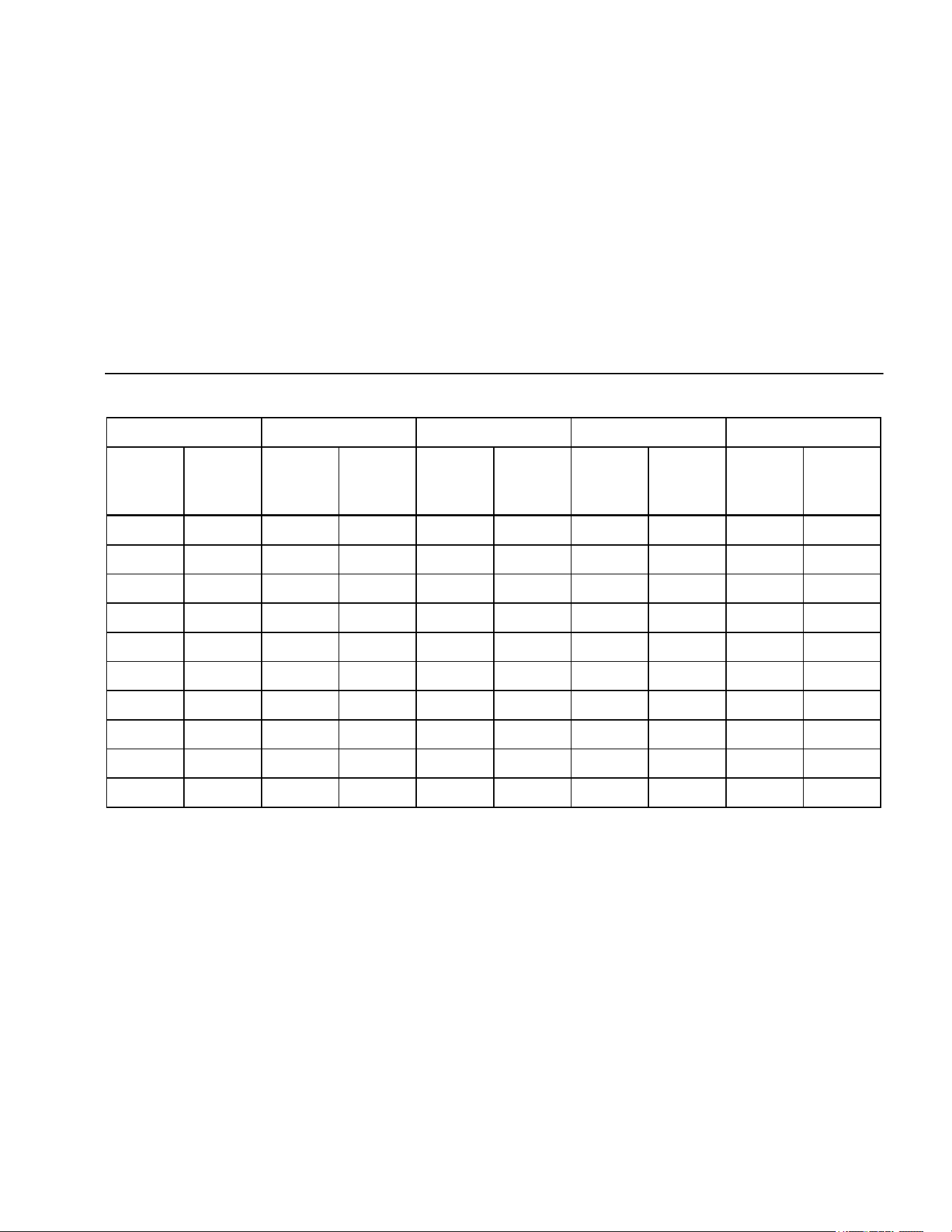
Insulation Resistance Maximum and Minimum Display Values (cont.)
50 V 100 V 250 V 500 V 1000 V
Limit
Value
Minimum
Display
Value
Limit
Value
Minimum
Display
Value
Limit
Value
Minimum
Display
Value
Limit
Value
Minimum
Display
Value
Limit
Value
Minimum
Display
Value
7.0 9.10 7.0 9.10 7.0 9.10 7.0 9.10 7.0 9.1
8.0 10.40 8.0 10.40 8.0 10.40 8.0 10.40 8.0 10.4
9.0 11.70 9.0 11.70 9.0 11.70 9.0 11.70 9.0 11.7
10.0 13.0 10.0 13.0 10.0 13.0 10.0 13.0 10.0 13.0
20.0 26.0 20.0 26.0 20.0 26.0 20.0 26.0 20.0 26.0
30.0 39.0 30.0 39.0 30.0 39.0 30.0 39.0 30.0 39.0
40.0 52.0 40.0 52.0 40.0 52.0 40.0 52.0 40.0 53.0
50.0 65.0 50.0 65.0 50.0 65.0 50.0 65.0
60.0 78.0 60.0 78.0 60.0 78.0 60.0 78.0
70.0 91.0 70.0 91.0 70.0 91.0 70.0 91.0
80.0 104.0 80.0 104.0 80.0 104.0 80.0 104.0
1.888.610.7664 sales@GlobalTestSupply.com
Fluke-Direct.com
Insulation Testers
Specifications
31
Insulation Resistance Maximum and Minimum Display Values (cont.)
50 V 100 V 250 V 500 V 1000 V
Limit
Value
Minimum
Display
Value
Limit
Value
Minimum
Display
Value
Limit
Value
Minimum
Display
Value
Limit
Value
Minimum
Display
Value
Limit
Value
Minimum
Display
Value
90.0 117.0 90.0 117.0 90.0 117.0 90.0 117.0
100.0 130.0 100.0 130.0 100.0 130.0
200.0 260.0 200.0 260.0
300.0 390.0 300.0 390.0
400.0 520.0 400.0 520.0
500.0 650.0
600.0 780.0
700.0 910.0
800.0 1040.0
900.0 1170.0
1000.0 1300.0
2000.0 2600.0
1.888.610.7664 sales@GlobalTestSupply.com
Fluke-Direct.com
1507/1503
Users Manual
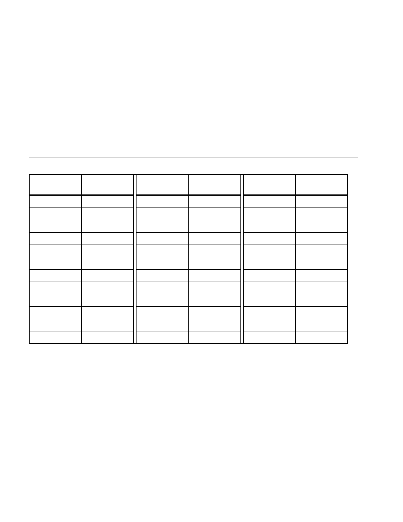
32
Earth-Bond Resistance Maximum Display Values
Limit Value
Maximum
Display Value
Limit Value
Maximum
Display Value
Limit Value
Maximum
Display Value
0.4 0.28 7.0 4.9 100.0 70.0
0.5 0.35 8.0 5.6 200.0 140.0
0.6 0.42 9.0 6.3 300.0 210.0
0.7 0.49 10.0 7.0 400.0 280.0
0.8 0.56 20.0 14.0 500.0 350.0
0.9 0.63 30.0 21.0 600.0 420.0
1.0 0.7 40.0 28.0 700.0 490.0
2.0 1.4 50.0 35.0 800.0 560.0
3.0 2.1 60.0 42.0 900.0 630.0
4.0 2.8 70.0 49.0 1000.0 700.0
5.0 3.5 80.0 56.0 2000.0 1400.0
6.0 4.2 90.0 63.0
1.888.610.7664 sales@GlobalTestSupply.com
Fluke-Direct.com