Loading ...
Loading ...
Loading ...
Video Wall Controller • Installation Guide
4
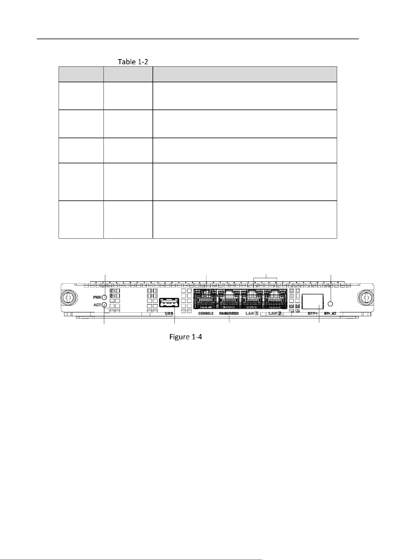
Main Control Board Interface Description
No.
Name
Description
1
PWR
Power indicator
Solid green after the board is powered on.
2
ACT
Status indicator
Flashing green when the board is functioning normally.
3
CONSOLE
Interface used for device debugging, parameter
configuration, etc.
4
LAN
Reserved LAN interface
Please connect to the network through the network
interface of the switch board.
5
USB
USB 2.0 interface
Used for connecting peripherals such as mouse,
keyboard, USB disk, etc.
Switch Board
1
2
3
4
5
6
7
8
Switch Board
Loading ...
Loading ...
Loading ...