
0
Video Wall Controller
Quick Start Guide
Video Wall Controller • Quick Start Guide
I
Legal Information
© 2023 Hangzhou Hikvision Digital Technology Co., Ltd. All rights reserved.
About this Manual
The Manual includes instructions for using and managing the Product. Pictures, charts, images and all other information
hereinafter are for description and explanation only. The information contained in the Manual is subject to change,
without notice, due to firmware updates or other reasons. Please find the latest version of this Manual at the Hikvision
website (https://www.hikvision.com/).
Please use this Manual with the guidance and assistance of professionals trained in supporting the Product.
Trademarks
and other Hikvision’s trademarks and logos are the properties of Hikvision in various jurisdictions.
Other trademarks and logos mentioned are the properties of their respective owners.
Disclaimer
TO THE MAXIMUM EXTENT PERMITTED BY APPLICABLE LAW, THIS MANUAL AND THE PRODUCT DESCRIBED, WITH ITS
HARDWARE, SOFTWARE AND FIRMWARE, ARE PROVIDED “AS IS” AND “WITH ALL FAULTS AND ERRORS”. HIKVISION
MAKES NO WARRANTIES, EXPRESS OR IMPLIED, INCLUDING WITHOUT LIMITATION, MERCHANTABILITY, SATISFACTORY
QUALITY, OR FITNESS FOR A PARTICULAR PURPOSE. THE USE OF THE PRODUCT BY YOU IS AT YOUR OWN RISK. IN NO
EVENT WILL HIKVISION BE LIABLE TO YOU FOR ANY SPECIAL, CONSEQUENTIAL, INCIDENTAL, OR INDIRECT DAMAGES,
INCLUDING, AMONG OTHERS, DAMAGES FOR LOSS OF BUSINESS PROFITS, BUSINESS INTERRUPTION, OR LOSS OF DATA,
CORRUPTION OF SYSTEMS, OR LOSS OF DOCUMENTATION, WHETHER BASED ON BREACH OF CONTRACT, TORT
(INCLUDING NEGLIGENCE), PRODUCT LIABILITY, OR OTHERWISE, IN CONNECTION WITH THE USE OF THE PRODUCT,
EVEN IF HIKVISION HAS BEEN ADVISED OF THE POSSIBILITY OF SUCH DAMAGES OR LOSS.
YOU ACKNOWLEDGE THAT THE NATURE OF THE INTERNET PROVIDES FOR INHERENT SECURITY RISKS, AND HIKVISION
SHALL NOT TAKE ANY RESPONSIBILITIES FOR ABNORMAL OPERATION, PRIVACY LEAKAGE OR OTHER DAMAGES
RESULTING FROM CYBER-ATTACK, HACKER ATTACK, VIRUS INFECTION, OR OTHER INTERNET SECURITY RISKS; HOWEVER,
HIKVISION WILL PROVIDE TIMELY TECHNICAL SUPPORT IF REQUIRED.
YOU AGREE TO USE THIS PRODUCT IN COMPLIANCE WITH ALL APPLICABLE LAWS, AND YOU ARE SOLELY RESPONSIBLE
FOR ENSURING THAT YOUR USE CONFORMS TO THE APPLICABLE LAW. ESPECIALLY, YOU ARE RESPONSIBLE, FOR USING
THIS PRODUCT IN A MANNER THAT DOES NOT INFRINGE ON THE RIGHTS OF THIRD PARTIES, INCLUDING WITHOUT
LIMITATION, RIGHTS OF PUBLICITY, INTELLECTUAL PROPERTY RIGHTS, OR DATA PROTECTION AND OTHER PRIVACY
RIGHTS. YOU SHALL NOT USE THIS PRODUCT FOR ANY PROHIBITED END-USES, INCLUDING THE DEVELOPMENT OR
PRODUCTION OF WEAPONS OF MASS DESTRUCTION, THE DEVELOPMENT OR PRODUCTION OF CHEMICAL OR
BIOLOGICAL WEAPONS, ANY ACTIVITIES IN THE CONTEXT RELATED TO ANY NUCLEAR EXPLOSIVE OR UNSAFE NUCLEAR
FUEL-CYCLE, OR IN SUPPORT OF HUMAN RIGHTS ABUSES.
IN THE EVENT OF ANY CONFLICTS BETWEEN THIS MANUAL AND THE APPLICABLE LAW, THE LATTER PREVAILS.
Video Wall Controller • Quick Start Guide
I
Regulatory Information
FCC Information
Please take attention that changes or modification not expressly approved by the party responsible
for compliance could void the user’s authority to operate the equipment.
FCC Compliance
This equipment has been tested and found to comply with the limits for a Class A digital device,
pursuant to part 15 of the FCC Rules. These limits are designed to provide reasonable protection
against harmful interference when the equipment is operated in a commercial environment. This
equipment generates, uses, and can radiate radio frequency energy and, if not installed and used in
accordance with the instruction manual, may cause harmful interference to radio communications.
Operation of this equipment in a residential area is likely to cause harmful interference in which
case the user will be required to correct the interference at his own expense.
FCC Conditions
This device complies with part 15 of the FCC Rules. Operation is subject to the following two
conditions:
1. This device may not cause harmful interference.
2. This device must accept any interference received, including interference that may cause
undesired operation.
EU Conformity Statement
This product and - if applicable - the supplied accessories too are marked with "CE" and
comply therefore with the applicable harmonized European standards listed under the
EMC Directive 2014/30/EU, the LVD Directive 2014/35/EU, the RoHS Directive 2011/65/EU.
2012/19/EU (WEEE directive): Products marked with this symbol cannot be disposed of as
unsorted municipal waste in the European Union. For proper recycling, return this product
to your local supplier upon the purchase of equivalent new equipment, or dispose of it at
designated collection points. For more information see: www.recyclethis.info
2006/66/EC (battery directive): This product contains a battery that cannot be disposed
of as unsorted municipal waste in the European Union. See the product documentation
for specific battery information. The battery is marked with this symbol, which may include
lettering to indicate cadmium (Cd), lead (Pb), or mercury (Hg). For proper recycling, return the
battery to your supplier or to a designated collection point. For more information see:
www.recyclethis.info
Video Wall Controller • Quick Start Guide
I
Preface
Applicable Models
This manual is applicable to C30 series video wall controllers.
About the Default
This device has the following defaults.
In order to improve system security, it is strongly recommended to reset your password
regularly. In order to protect your personal privacy and corporate data, and avoid network
security issues on your device, it is recommended that you set a high-strength password that
complies with security regulations.
Symbol Conventions
The symbols that may be found in this document are defined as follows.
Category
Parameter
Default Value
Device
Login username and IP
address
User name: admin
IP Address: 192.0.0.64
Symbol
Description
Provides additional information to emphasize or supplement
important points of the main text.
Indicates a potentially hazardous situation, which if not avoided,
could result in equipment damage, data loss, performance
degradation, or unexpected results.
Indicates a hazard with a high level of risk, which if not avoided, will
result in death or serious injury.
Video Wall Controller • Installation Guide
II
Safety Instructions
In the use of the product, you must be in strict compliance with the electrical safety
regulations of the nation and region.
This is a class A product and may cause radio interference in which case the user may be
required to take adequate measures.
Use the power adapter delivered with the device only.
This equipment is not suitable for use in locations where children are likely to be present.
CAUTION: Risk of explosion if the battery is replaced by an incorrect type.
Improper replacement of the battery with an incorrect type may defeat a safeguard (for
example, in the case of some lithium battery types).
Do not dispose of the battery into fire or a hot oven, or mechanically crush or cut the battery,
which may result in an explosion.
Do not leave the battery in an extremely high temperature surrounding environment, which
may result in an explosion or the leakage of flammable liquid or gas.
Do not subject the battery to extremely low air pressure, which may result in an explosion or
the leakage of flammable liquid or gas.
Waste batteries will pollute the environment. Please dispose of used batteries according to the
instructions.
Do not expose the battery to the sun, fire or other similar overheated environment.
The protective ground terminal of the equipment should be reliably connected to the
protective grounding device of the building.
The device contains fans. Keep body parts away from fan blades. Disconnect the power source
during maintenance.
If the product does not work properly, please contact your dealer or the nearest service
center. Never attempt to disassemble the product yourself. (We shall not assume any
responsibility for problems caused by unauthorized repair or maintenance.)
If smoke, odor or noise rise from the device during use, please turn off the power at once and
unplug the power cable, and then contact the service center.
The device is a system-level monitoring equipment, which is generally placed in the central
computer room of the monitoring system at all levels. The selection of the installation site
should comply with the relevant standards of the computer room construction in the country
and region of use.
The device is only suitable for installation in the computer room.
Please install the device according to the instructions in this manual. To prevent injury, this
device must be securely attached to the installation location.
Do not place the device in an environment with strong vibration, impact, or strong
electromagnetic interference (ignorance can cause equipment damage).

Video Wall Controller • Installation Guide
III
Do not expose the device to the explosive situation.
Keep clean and dry on the surface of the device.
Do not touch the exposed connection points or components when the device is powered on.
Keep a minimum 25 cm distance around the device for sufficient ventilation.
The ventilation should not be impeded by covering the ventilation openings with items, such
as newspapers, table-cloths, curtains, etc. The openings shall never be blocked by placing the
device on a bed, sofa, rug or other similar surface.
Video Wall Controller • Installation Guide
IV
TABLE OF CONTENTS
Chapter 1 Introduction ............................................................................................................... 1
Overview ............................................................................................................................................................... 1
Packing List ........................................................................................................................................................... 1
Device Appearance ............................................................................................................................................... 2
1.3.1 Host System ............................................................................................................................................... 2
1.3.2 Functional Service Board ........................................................................................................................... 5
Chapter 2 Installation ............................................................................................................... 13
Safety Precautions .............................................................................................................................................. 13
Install Board Card ................................................................................................................................................ 15
Install Cabinet and Grounding ............................................................................................................................ 16
Connect Cables ................................................................................................................................................... 17
2.4.1 Connect Network ..................................................................................................................................... 17
2.4.2 Connect Power Cord ................................................................................................................................ 18
Power the Device On .......................................................................................................................................... 18
Chapter 3 Get More Information ............................................................................................... 19

Video Wall Controller • Quick Start Guide
1
Chapter 1 Introduction
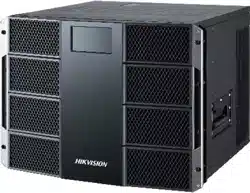
Overview
The DS-C30S series video wall controller (hereinafter referred to as “the device”, or the
“controller”) is a new-generation pure hardware image processing device based on Field
Programmable Gate Array (FPGA). Compared with the traditional controller, the device has a
brand-new system structure and adopts data dual exchange technology to support large-capacity
data transmission and processing. With high image processing performance, the device supports
the access and real-time processing of multi-channel high definition and ultra-high definition
signals. Adopting the main control board plus input and output board structure, which can be
figured as required, the device supports multi-screen management. This product is mainly used in
large-screen splicing control system and considered the core control device of the system.
Video Wall Controller • Quick Start Guide
1
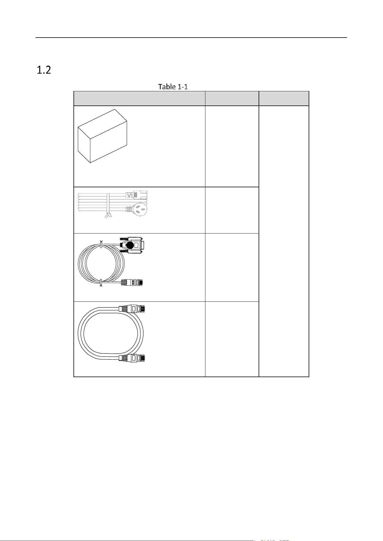
Packing List
Packing List
Item
Quantity
Device
Redundant Power Supply
3
Chassis
AC Power Cord
2
DB9 to RJ45 Converter
1
Network Cable
2
Video Wall Controller • Installation Guide
2
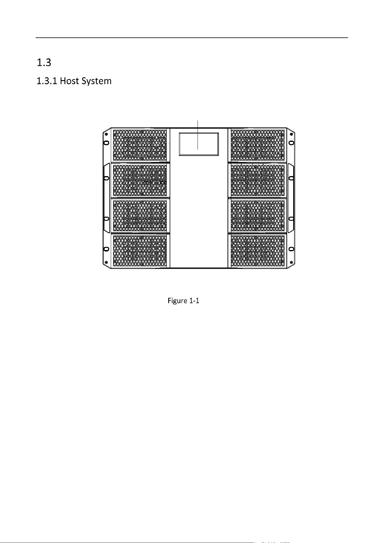
Device Appearance
The front view of the host system.
LCD
Front View
Video Wall Controller • Installation Guide
3
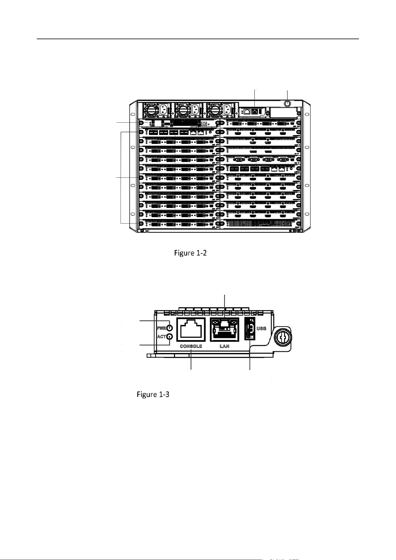
The rear view of the host system.
Switch
Board
Service
Board
Mother
Board
Power
Switch
Rear View
Main Control Board
1
2
4
3
5
Front Panel of Main Control Board
Video Wall Controller • Installation Guide
4
Main Control Board Interface Description
No.
Name
Description
1
PWR
Power indicator
Solid green after the board is powered on.
2
ACT
Status indicator
Flashing green when the board is functioning normally.
3
CONSOLE
Interface used for device debugging, parameter
configuration, etc.
4
LAN
Reserved LAN interface
Please connect to the network through the network
interface of the switch board.
5
USB
USB 2.0 interface
Used for connecting peripherals such as mouse,
keyboard, USB disk, etc.
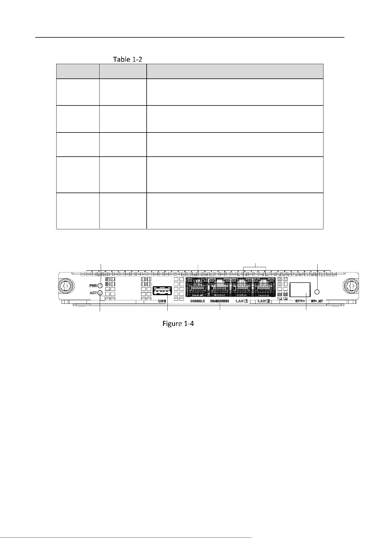
Switch Board
1
2
3
4
5
6
7
8
Switch Board
Video Wall Controller • Installation Guide
5
Switch Board Interface Description
No.
Name
Description
1
PWR
Power indicator
Solid green after the board is powered on.
2
ACT
Status indicator
Flashing green when the board is functioning normally.
3
USB
Reserved USB 2.0 interface
Used for connecting peripherals such as mouse,
keyboard, U disk, etc.
4
CONSOLE
Interface used for device debugging, parameter
configuration, etc.
5
RS485/RS232
RJ45 interface
Used for screen control, serial port keyboard control,
etc.
6
LAN
2 LAN interfaces
Used for network connection.
7
SFP
Interface used for the insertion of one 10 Gigabit
optical port module.
8
SFP ACT
Status indicator of SFP
• Lit when inserted with optical port module
• Flashes during data trasmission
The device adopts a plug-in modular design. The host system is equipped with different service sub-
boards to achieve different functions.
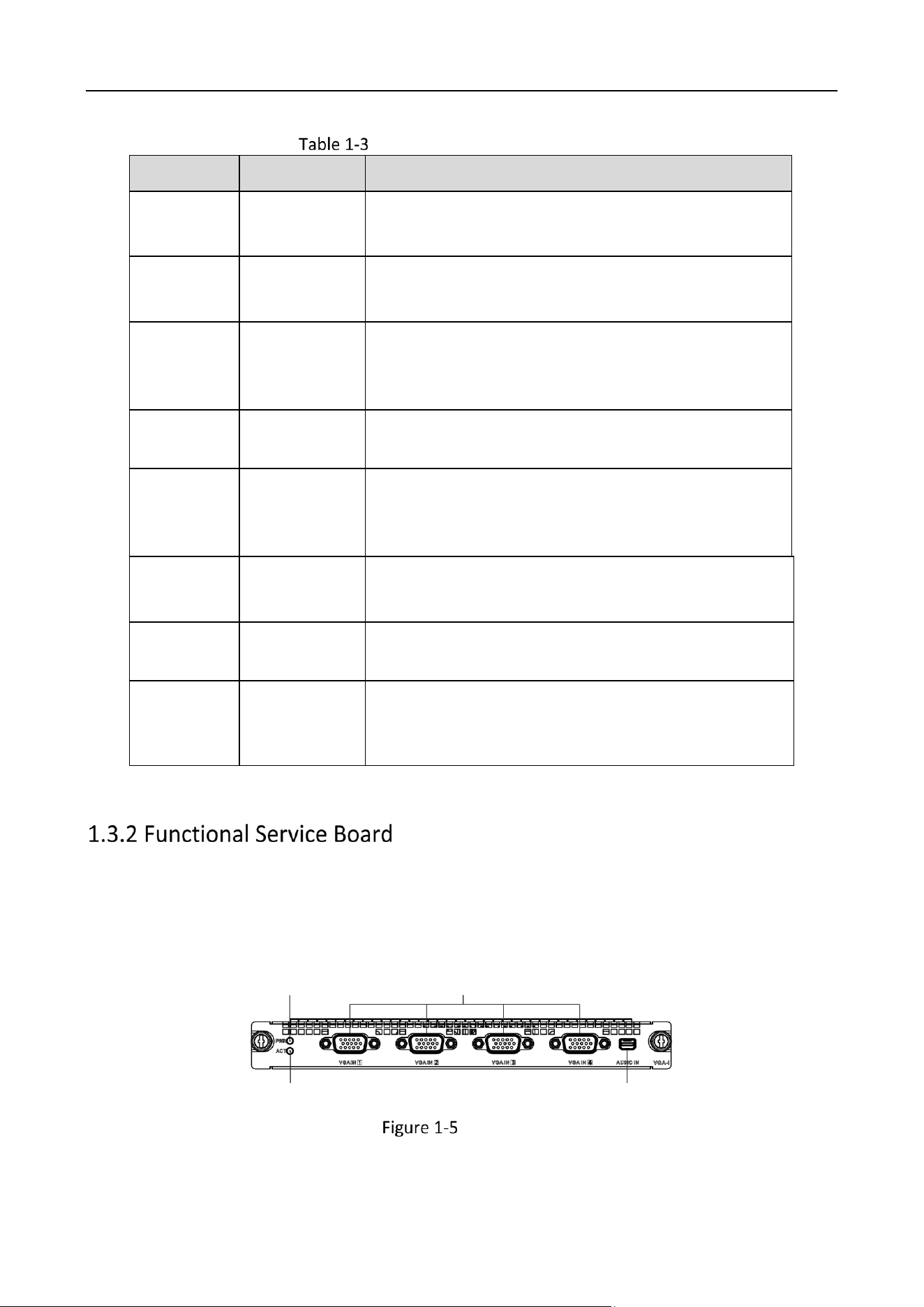
VGA Input Board
1
2
3
4
VGA Input Board
Video Wall Controller • Installation Guide
6
VGA Input Board Interface Description
No.
Name
Description
1
PWR
Power indicator
Solid green after the board is power-on.
2
ACT
Status indicator
Flashing green when the board is functioning normally.
3
VGA IN
4 interfaces used for VGA video input.
4
AUDIO IN
Mini-DP four-in-one Line-in audio input interface
Used for audio input with an external adapter cable.
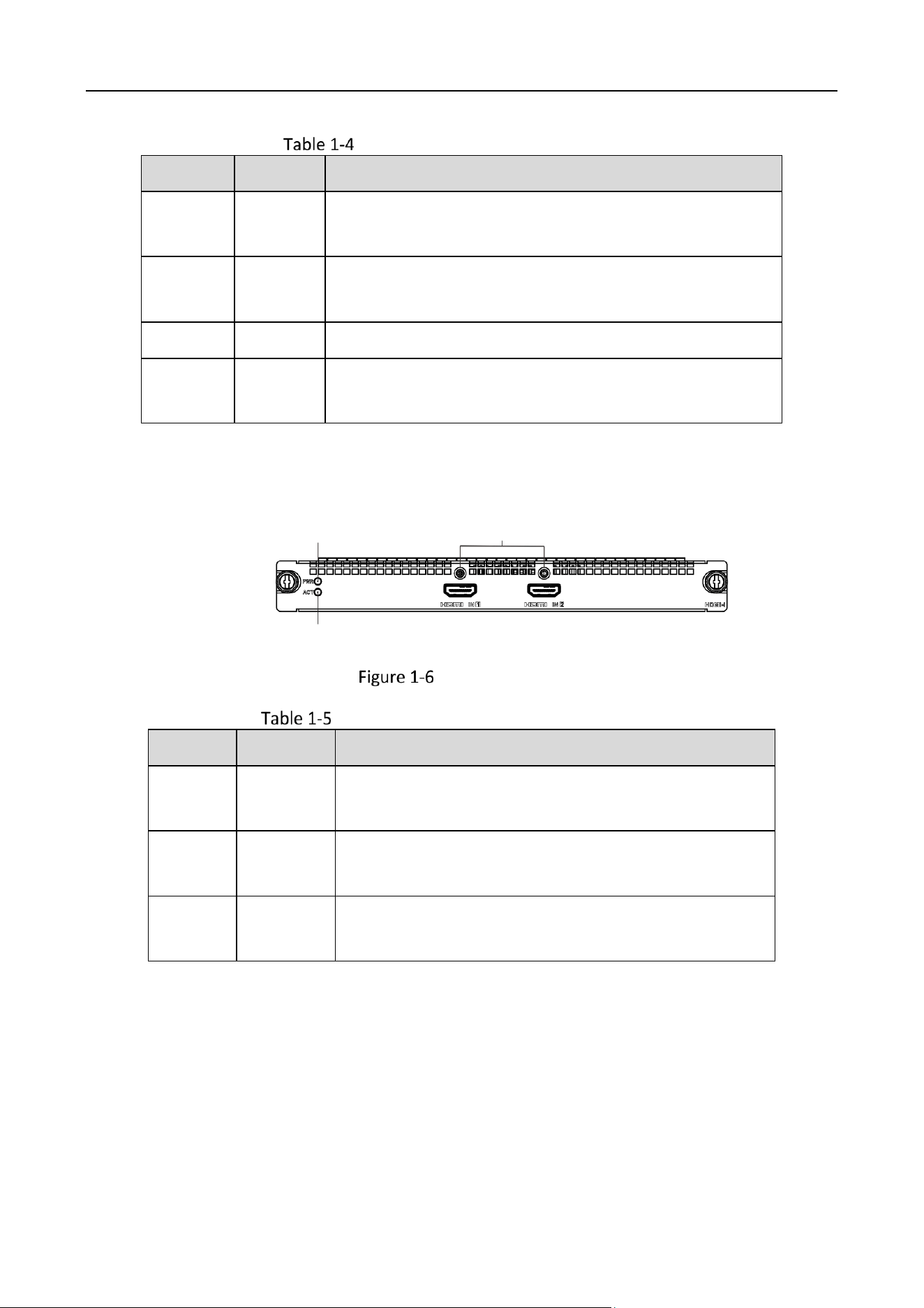
HDMI UHD Input Board
1
2
3
HDMI UHD Input Board
HDMI UHD Input Board Interface Description
No.
Name
Description
1
PWR
Power indicator
Solid green after the board is power-on.
2
ACT
Status indicator
Flashing green when the board is functioning normally.
3
HDMI IN
2 HDMI
Used for ultra-high-definition video input.
Video Wall Controller • Installation Guide
7
DP Input Board
1
2
1 3
DP Input Board
DP Input Board Interface Description
No.
Name
Description
1
PWR
Power indicator
Solid green after the board is power-on.
2
ACT
Status indicator
Flashing green when the board is functioning normally.
3
DP IN
2 DP interfaces
Used for ultra-high-definition video input.
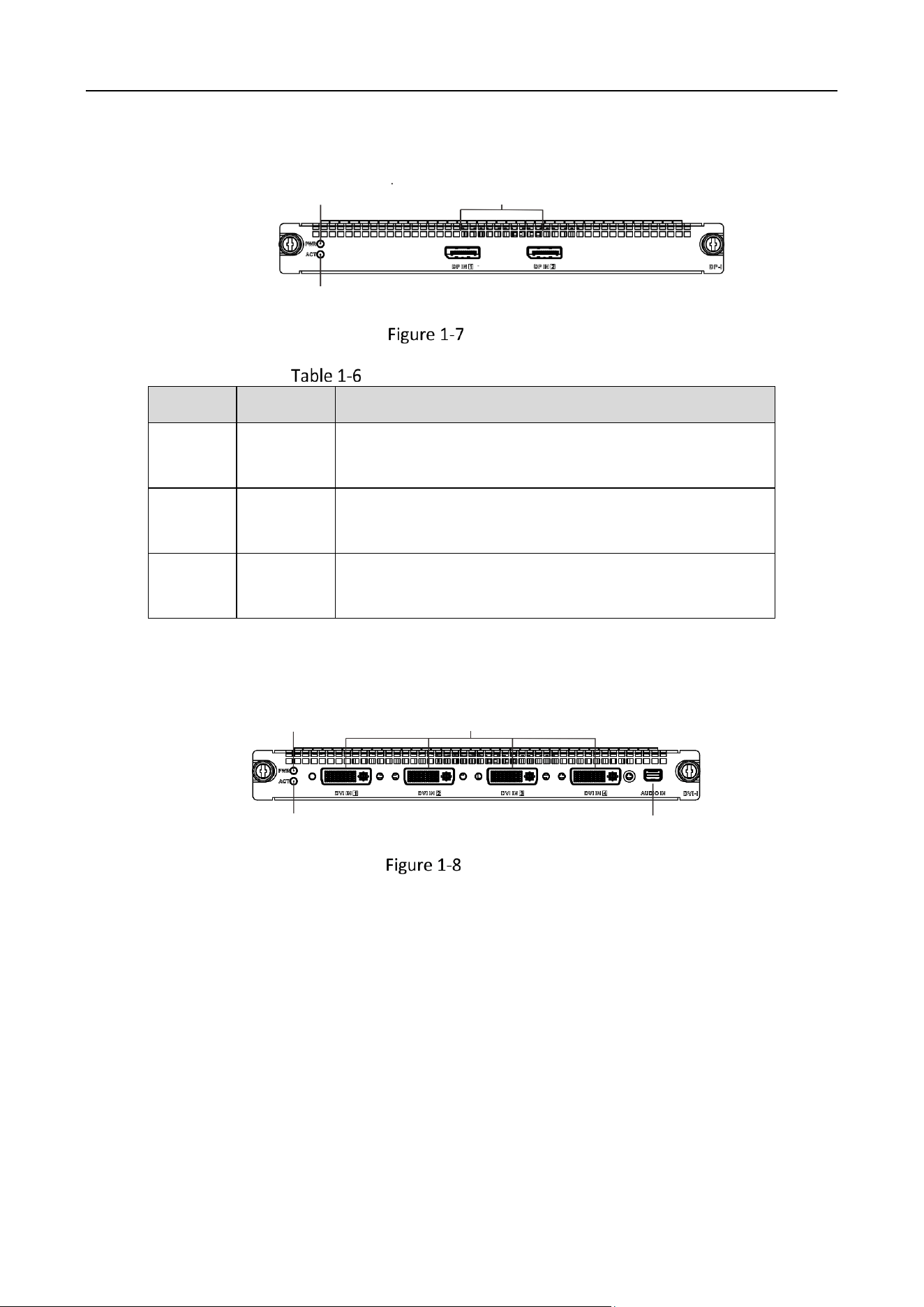
DVI Input Board
1
2
3
4
DVI Input Board
Video Wall Controller • Installation Guide
8
DVI Input Board Interface Description
No.
Name
Description
1
PWR
Power indicator
Solid green after the board is powered on.
2
ACT
Status indicator
Flashing green when the board is functioning normally.
3
DVI IN
4 DVI IN
Used for video input.
4
AUDIO IN
Mini-DP four-in-one Line-in audio input interface
Used for audio input with an external adapter cable.
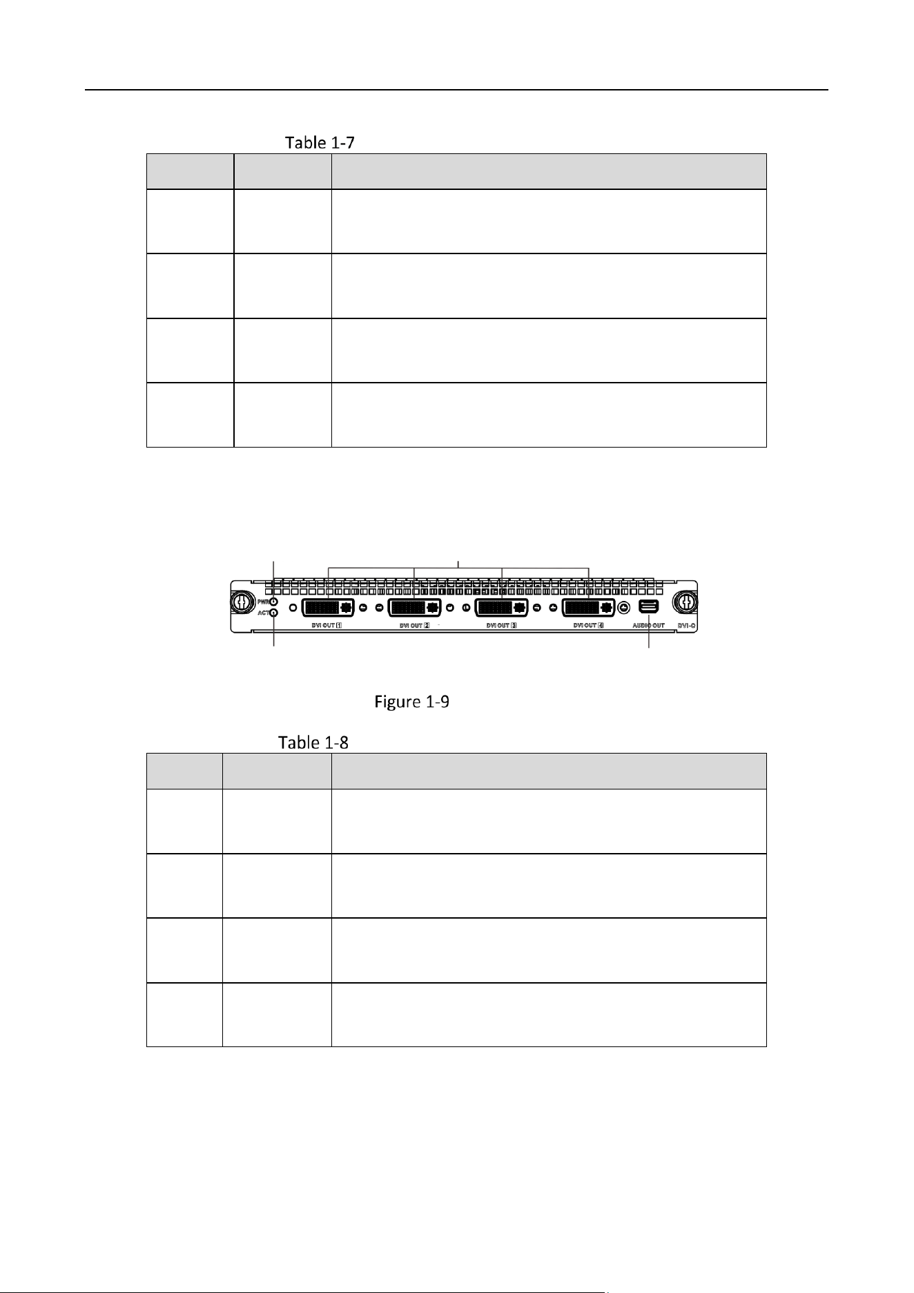
DVI Output Board
1
2
3
4
DVI Output Board
DVI Output Board Interface Description
No.
Name
Description
1
PWR
Power indicator
Solid green after the board is powered on.
2
ACT
Status indicator
Flashing green when the board is functioning normally.
3
DVI OUT
4 DVI OUT
Used for video output.
4
AUDIO OUT
Mini-DP four-in-one Line-in audio output interface
Used for audio output with an external adapter cable.
Video Wall Controller • Installation Guide
9
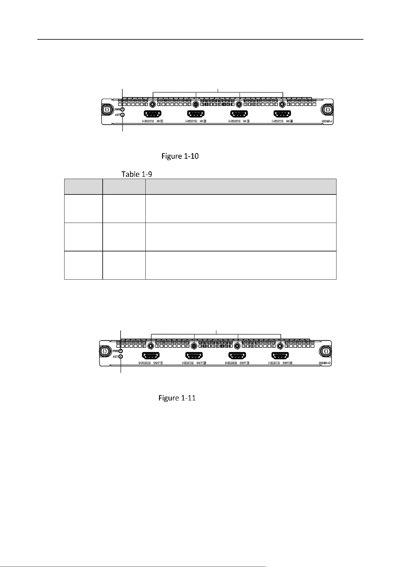
HDMI Input Board
1
2
3
HDMI Input Board
HDMI Input Board Interface Description
No.
Name
Description
1
PWR
Power indicator
Solid green after the board is powered on.
2
ACT
Status indicator
Flashing green when the board is functioning normally.
3
HDMI IN
4 HDMI IN
Used for video input.
HDMI Output Board
1
2
3
HDMI Output Board
Video Wall Controller • Installation Guide
10
HDMI Output Board Interface Description
No.
Name
Description
1
PWR
Power indicator
Solid green after the board is powered on.
2
ACT
Status indicator
Flashing green when the board is functioning normally.
3
HDMI OUT
4 HDMI OUT
Used for video output.
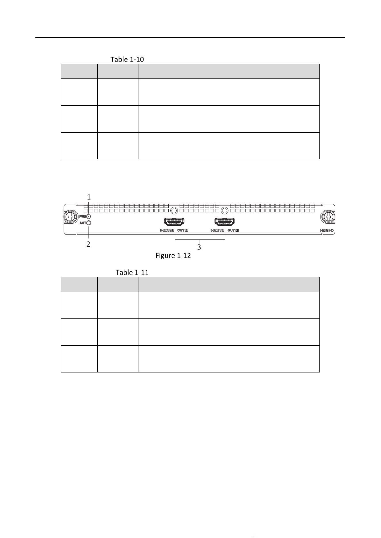
4K Output Board
4K Output Board
4K Output Board Interface Description
No.
Name
Description
1
PWR
Power indicator
Solid green after the board is powered on.
2
ACT
Status indicator
Flashing green when the board is functioning normally.
3
HDMI OUT
2 4K HDMI OUT
Used for video output.
Video Wall Controller • Installation Guide
11
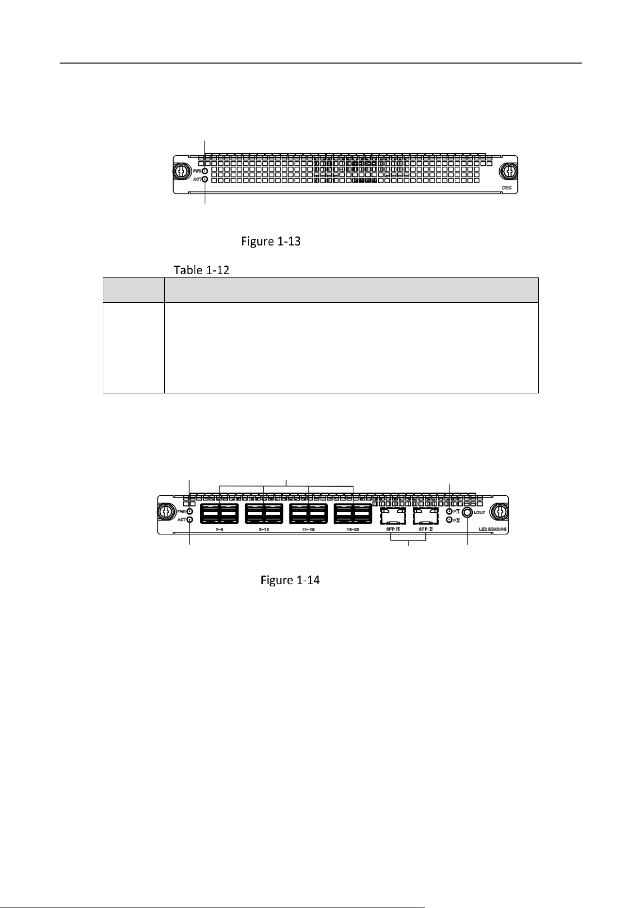
Network Decoding Board
1
2
Network Decoding Board
Network Decoding Board Interface Description
No.
Name
Description
1
PWR
Power indicator
Solid green after the board is powered on.
2
ACT
Status indicator
Flashing green when the board is functioning normally.
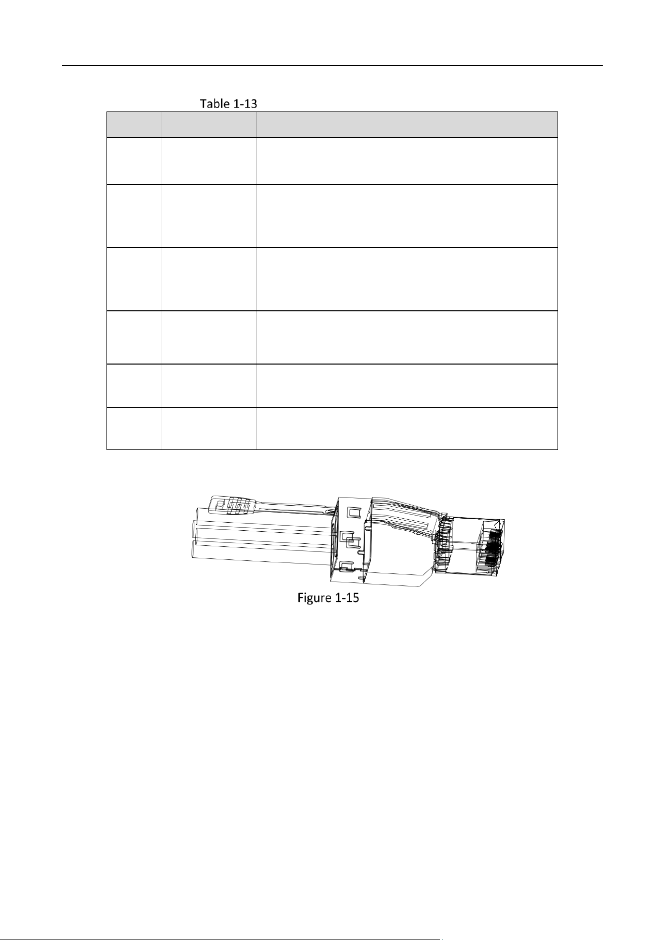
LED Sending Card
1
2
3
4
5
6
LED Sending Card
Video Wall Controller • Installation Guide
12
LED Sending Card Interface Description
No.
Name
Description
1
PWR
Power indicator
Solid green after the board is powered on.
2
ACT
Status indicator
Flashing green when the board is functioning
normally.
3
Gigabit
Network
Interface
20 Gigabit Ethernet interfaces
Used for network connection through MiniSAS 8x to
RJ45.
4
SFP
2 SFP interfaces
Used for the insertion of 10 Gigabit optical port
module.
5
SFP Indicator
Status indicator of SFP
Turns steady green when SFP functions normally.
6
AUDIO OUT
Interfasce used for Line-out audio output through left
and right channels or two separate channels.
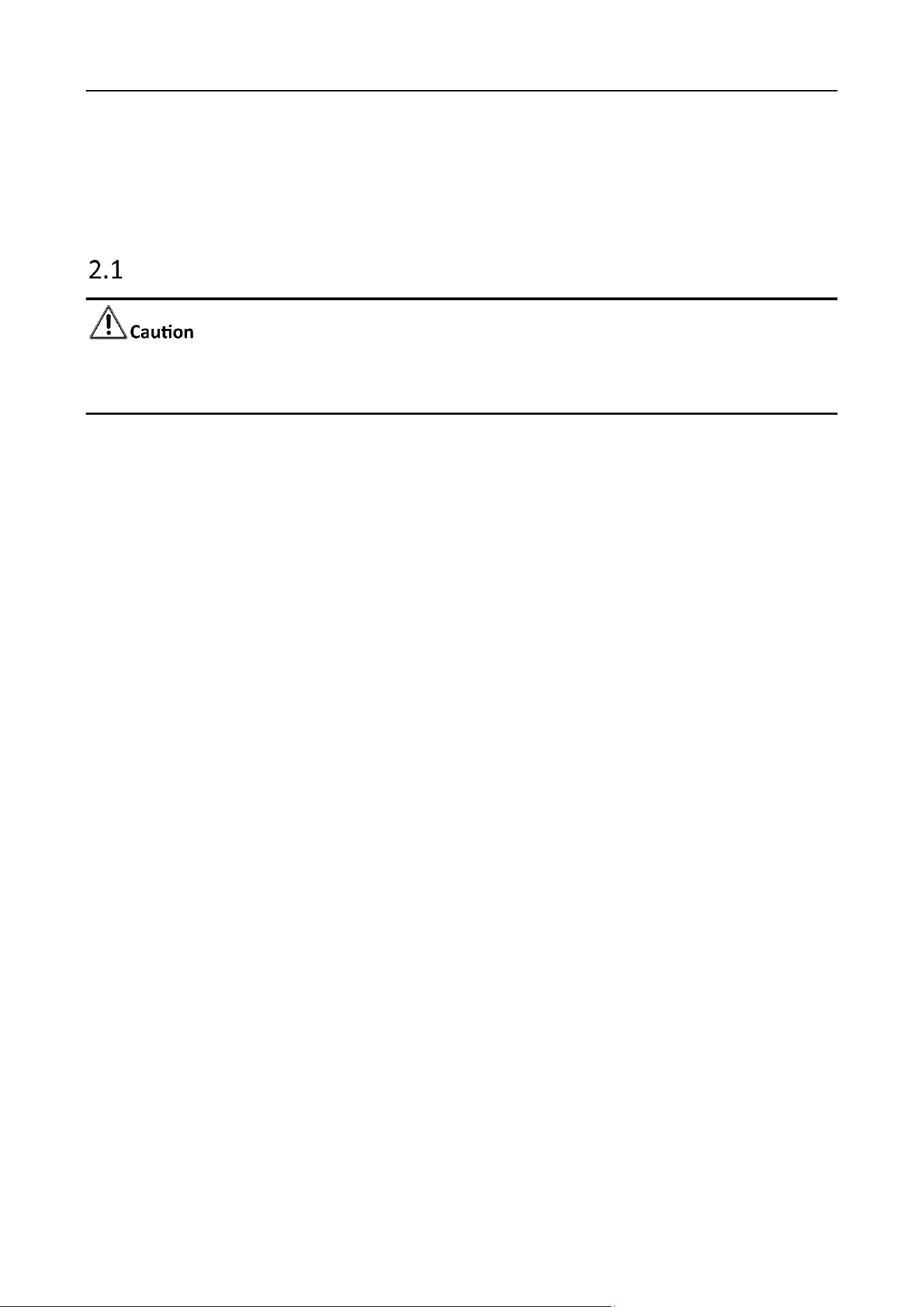
MiniSAS 8x to RJ45
Video Wall Controller • Quick Start Guide
13
Chapter 2 Installation
Safety Precautions
As a high-precision, system-level electronic product, the controller should be installed and
maintained by professionals.
In order to avoid personal and property injury, please read the safety precautions in this section
carefully before installation. The following safety recommendations do not cover all possible
dangerous situations.
Electricity Safety
During the installation, wiring, disassembly, and maintenance of the device, please
disconnect the power supply and do not operate with electricity (except for the
operation of the hot plug).
In the installation and use of the device, make sure to follow the local electrical safety
regulations.
Please use the power adapter provided with the device.
In case of abnormal phenomena such as smoke or peculiar small occur during the use of
the device, please cut off the power immediately, unplug the power cord from the
socket, and contact the after-sales service center in time.
Anti-Static Measures
The equipment is a precision electronic device. In order to avoid static electricity from damaging
the components, in addition to anti-static measures in the installation room, you also need to
pay attention to the following measures:
During the installation process (especially when installing the main control board and
the business board), you must wear anti-static gloves or anti-static wrists.
When holding the main control board or the business board, try to avoid touching the
components or printed circuits.

Video Wall Controller • Installation Guide
14
Grounding Requirements
In order to ensure personal safety and device safety, the device must be grounded. See “2.3 for
detailed steps.
Power Supply Requirements
The device supports AC 106 ~ 240 V, 50/60 Hz power supply. It is recommended to use AC 220
V power supply. To ensure the stable operation of the device, it is recommended to install UPS
for power supply.
Anti-Interference Requirements
The on-site power supply system must have effective measures to prevent grid
interference.
Do not use the working ground together with the grounding device or lightning
protection grounding device of power equipment, and keep the two as far away as
possible.
Keep away from high-power radio transmitters, radar transmitters, and high-frequency
and high-current equipment.
When necessary, electromagnetic shielding can be used for anti-interference.
Environmental Requirements
The device is a system-level monitoring equipment, which is generally placed in the central
computer room of the monitoring system at all levels. The selection of the installation site
should comply with the relevant standards of the computer room construction in the country
and region of use.
The device is a standard rack-mounted equipment fixed in the cabinet. Please pay attention to
the following information during installation and use:
Ensure that the temperature in the cabinet is within the range of 0 °C to 50 °C .
Ensure that the humidity in the equipment room is between 10% and 90% RH.
Ensure that the cabinet is strong enough to support the weight of the video integrated
platform and its accessories. Pay attention to avoid the danger caused by uneven
mechanical load during the simultaneous installation.
Ensure that there is enough installation space for the video and audio cables. The cable
bending radius should not be less than 5 times the cable outer diameter.
Keep the integrated platform a minimum 50 cm distance above the ground for sufficient
ventilation.
Video Wall Controller • Installation Guide
15
Install Board Card
The device is of plug-in modular design. All functions are realized through the service board, and
managed through the main control board. The basic steps to install the board card are illustrated
as follows.
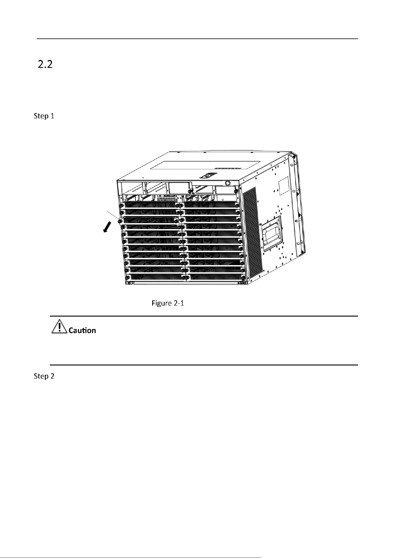
Remove some (or all) baffle from the slots of the device as required.
Loosen the fixing screws on both sides with a screwdriver and pull out the baffle.
档板
Baffle
Remove the Baffle
Do not remove the baffle from the slot where the board is not installed, so as not to affect the
cooling air passage.
Install the board. Take the installation of the service board as an example.
1. Insert the service board along the slot.
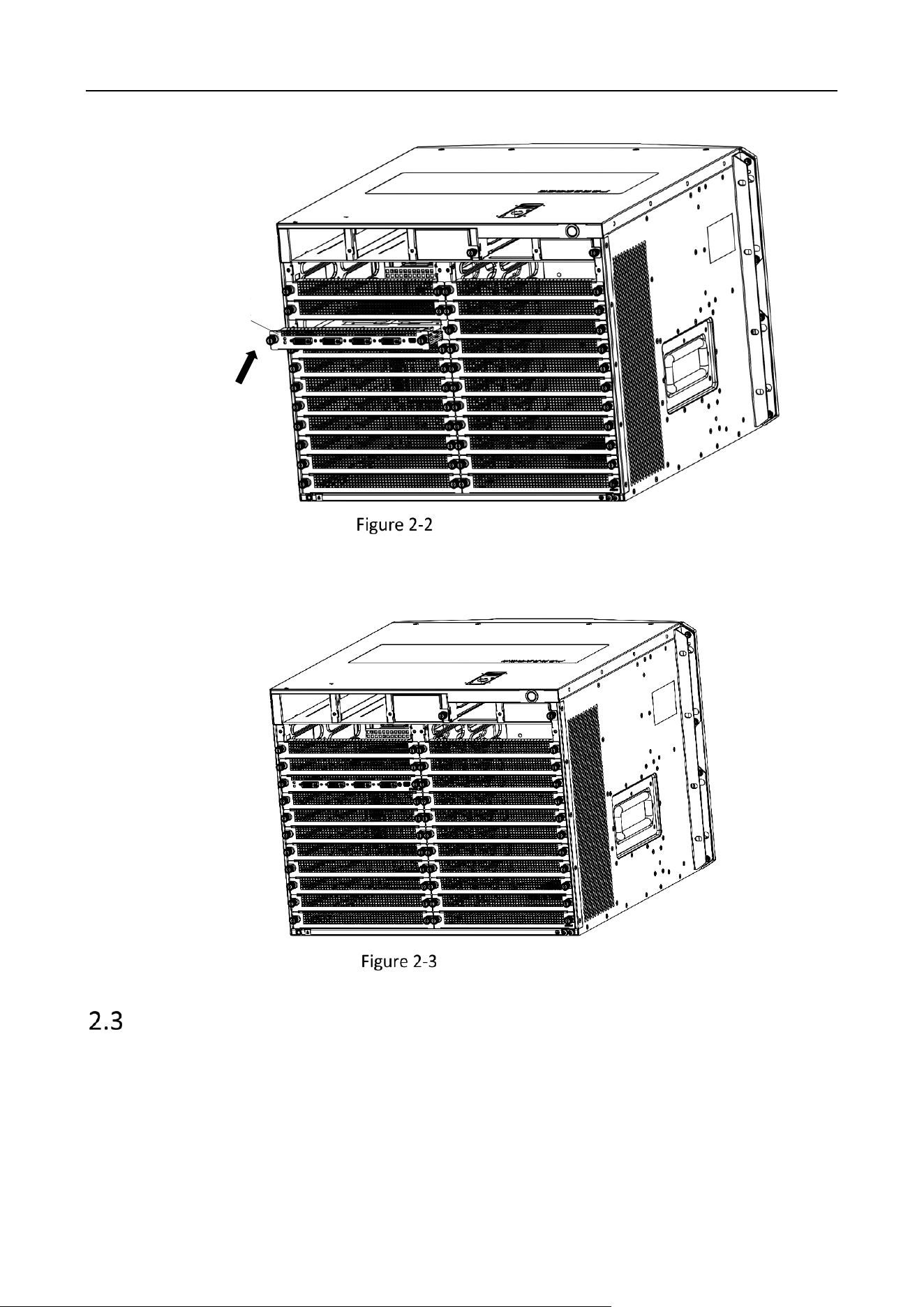
Video Wall Controller • Installation Guide
16
业务板
Service
Board
Insert the Service Board
2. Push the board to the innermost position.
3. Fix the screws on both sides with a screwdriver.
Installation Completed
Install Cabinet and Grounding
The device is designed in accordance with the 8U standard chassis structure. The installation process
is as follows.
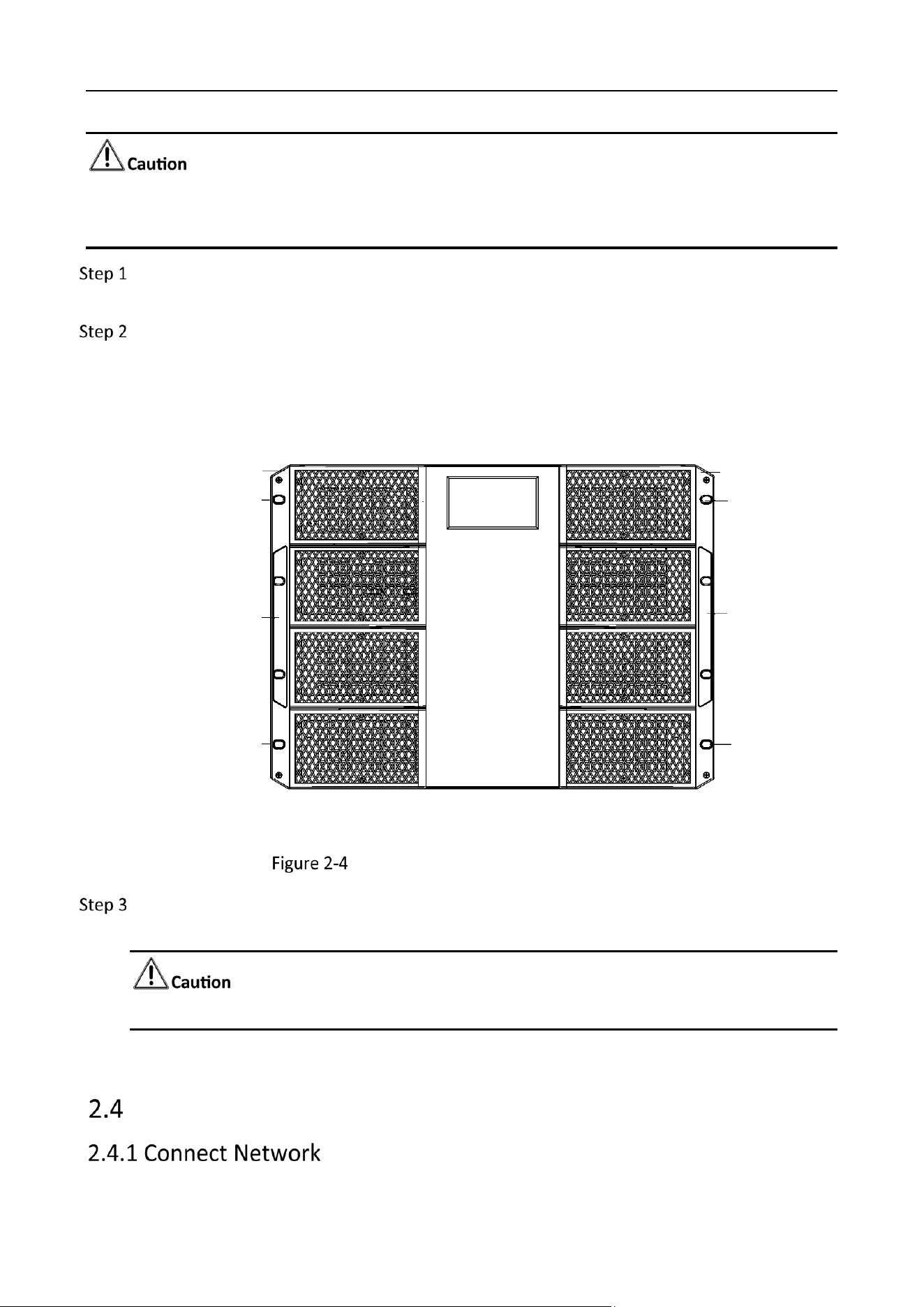
Video Wall Controller • Installation Guide
17
The front and rear weights of the chassis are inconsistent. Please take safety precautions when lifting
the chassis.
Install the rack bracket on an empty slot of the rack (make sure it can bear the weight of the
device), and fix it with screws.
Place the device on the bracket, and fix the body mounting ears on the fixed guide grooves
on both sides of the cabinet with screws.
The positions of the fixed screws for the chassis mounting ears are shown as follows.
Mounting Ear Mounting Ear
Fixed Srew
Fixed Srew
Fixed Srew
Fixed Srew
Mounting Ear
Handle
Mounting Ear
Handle
Locations of the Fixed Screws for the Chassis Mounting Ears
Make reliable grounding between the grounding terminal of the device and the cabinet. The
grounding point is located on the rear of the chassis.
To ensure personal safety and equipment safety, the device must be grounded.
Connect Cables
Video Wall Controller • Installation Guide
18
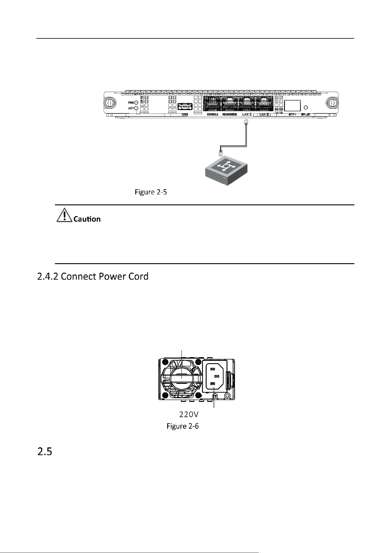
The device is connected to the network through networking equipment such as switches. The
following figure is an example of the switch board network connection.
交换板
Switch
Board
Switch Board Network Connection
It is recommended to use Category 6 Ethernet cable for connection.
The default configuration of the 2 Gigabit Ethernet ports on the device is not aggregated.
Aggregation can be realized as long as the connected switch board is configured.
Use three-phase power cord to connect the equipment power supply to the power supply socket in
the server room.
The device is equipped with redundant dual power supplies, and both power interfaces need to be
connected to power socket(s).
Fan
Power Input
Power Supply
Power the Device On
You can start the device after the power cord is connected. Press and hold the power switch during
operation to shut down the device. Short press the power switch in the shutdown state to start the
device.
Video Wall Controller • Quick Start Guide
19
Chapter 3 Get More Information
Scan the QR code below to get more information about the system operation and function
configuration. Please refer to the actual device.
The following operations require network data traffic and are recommended to be performed in a
Wi-Fi environment.
User Manual
Communication Matrix
Device Command

0
UD31558B