
1
Owner’s Manual
Este manual está disponible en español en la página de Eaton:
Tripplite.Eaton.com/support
Ce manuel est disponible en français sur le site Web de Eaton :
Tripplite.Eaton.com/support
Dieses Handbuch ist in deutscher Sprache auf der Eaton-Website verfügbar:
Tripplite.Eaton.com/support
Questo manuale è disponibile in italiano sul sito web di Eaton:
Tripplite.Eaton.com/support
Purchased product
may differ from image.
Model:
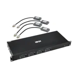
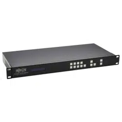
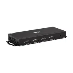
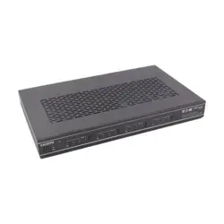
B119-4X4-4K6-VW
4x4 HDMI Matrix Switch/Splitter –
4K 60 Hz

2
Table of Contents
1. Safety Instructions 3
2. Introduction 3
3. Product Features 4
4. Package Contents 4
5. Specifications 5
6. Operation Controls and Functions 6
7. IR Remote 7
8. IR Cable Pin Assignment 8
9. EDID Management 9
10. Video Wall 10
11. Web GUI User Guide 11
12. RS-232 Control Command 22
13. Application Example 30
14. Warranty 31
3
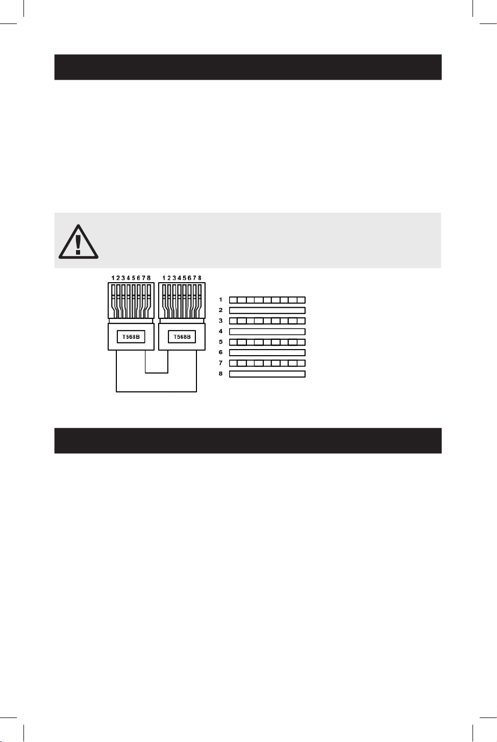
CAUTION
This product requires the use of UTP connectors. Please connect
in direct interconnection method and do not cross-connect.
1. Safety Instructions
2. Introduction
Thank you for purchasing the B119-4X4-4K6-VW. For optimum performance and
safety, please read these instructions carefully before connecting, operating or
adjusting this product. Please keep this manual for future reference.
Surge Protection Device Recommended
This product contains sensitive electrical components that may be damaged by
electrical spikes, surges and other power interruptions. Use of surge protection
systems is highly recommended in order to protect and extend the life of your
equipment.
The 4x4 HDMI Matrix Switch/Splitter is a multi-purpose high-speed video processing
system that you can configure for two different output modes.
It features a web browser interface module for control and configuration of the unit
when used stand-alone or with a third-party control system.
You can control the HDMI Matrix Switch/Splitter using front-panel buttons, the
included IR remote, RS-232 commands or TCP/IP.
White and Orange
Orange
White and Green
Blue
White and Blue
Green
White and Brown
Brown

4
3. Product Features
4. Package Contents
• Features 2 operational modes: 4x4 matrix (seamless switch) and video wall (2x2,
4x1, 1x4, etc.)
• Video inputs support all industry-standard video resolutions, including VGA–
WUXGA (up to 1920 × 1200 @ 60 Hz) and 480i–4K (3840 x 2160 @ 60 Hz 4:4:4,
4096 x 2160 @ 60 Hz 4:4:4)
• HDCP 2.2 and HDCP 1.4 compliant
• HDMI outputs support upscale or downscale to any resolution up to 4096 x 2160
@ 60 Hz 4:4:4
• Support LPCM, Dolby Digital, Dolby Digital Plus, DTS, Dolby TrueHD and DTS
HD-master pass-through
• Advanced EDID management
• Web interface module for control and configuration of the unit
• Control via front-panel buttons, IR remote, RS-232 commands or TCP/IP
• Third-party drivers available for all major home control brands
• 4x4 HDMI Matrix Switch/Splitter
• External Power Supply
• 12V 2.5A Locking Power Plug (AS/NZS 3112 Australia, BS 1363 U.K., CEE 7/16
Schuko, NEMA 1-15P North America)
• IR Remote
• 20–60KHz IR Wideband Receiver Cable, 5 ft. (1.5 m)
• 3-Pin 3.81 mm Phoenix Connector
• (4) KM 3x4 Machine Screws
• (2) Mounting Ears
• User Documentation

5
5. Specifications
Technical
HDMI Compliance HDMI 2.0b
HDCP Compliance HDCP 2.2/1.4
Video Bandwidth 594 MHz/18 Gbps
Video Resolution Input: VGA–WUXGA (up to 1920 × 1200 @ 60 Hz) and
480i–4K (3840 x 2160 @ 60 Hz 4:4:4, 4096 x 2160 @
60 Hz 4:4:4)
Output: 4096 x 2160p @ 60 Hz, 4096 x 2160p @ 50 Hz,
3840 x 2160p @ 60 Hz, 3840 x 2160p @ 50 Hz,
3840 x 2160p @ 30 Hz, 1920 x 1080p @ 60 Hz,
1920 x 1080p @ 50 Hz, 1920 x 1080i @ 60 Hz,
1920 x 1080i @ 50 Hz, 1920 x 1200p @ 60 Hz,
1360 x 768p @ 60 Hz, 1280 x800p @ 60 Hz, 1280 x720p
@ 60 Hz, 1280 x 720p @ 50 Hz, 1024 x768p @ 60 Hz,
Auto
Color Space RGB, YCbCr_4:4:4, YCbCr_4:2:2, YCbCr_4:2:0
Color Depth 8/10/12 bit
IR Level 12Vp-p
IR Frequency 38 kHz
HDMI Audio Formats LPCM, Dolby Digital/Plus/EX, Dolby True HD, DTS, DTS-EX,
DTS-96/24, DTS High Res, DTS-HD Master Audio
Connection
Input Ports 4 × HDMI [Type A, 19-pin female]
Output Ports 4 × HDMI [Type A, 19-pin female]
Control Ports 1 × RS-232 [3-pin 3.81mm Phoenix Connector]
1 × IR EXT [3.5 mm, Stereo Mini-Jack]
1 x TCP/IP (RJ45)
Mechanical
Housing Metal
Color Black
Dimensions (H x W x D) 1.2 x 10.6 x 6.5 in. / 30 x 270 x 166 mm
Weight 2.6 lb. / 1165 g
Power Supply Input: AC 100–240V, 50/60 Hz
Output: DC 12V 2.5A
(US/EU Standard, CE/FCC/UL Certied)
Power Consumption 19.56W (Max)
Operating Temperature 32° - 104°F / 0° - 40°C
Storage Temperature -4° - 140°F / -20° - 60°C
Relative Humidity 20% - 90% RH (Non-Condensing)
6
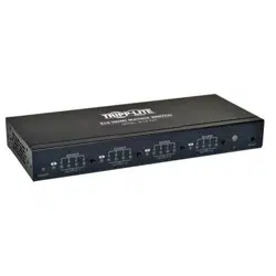
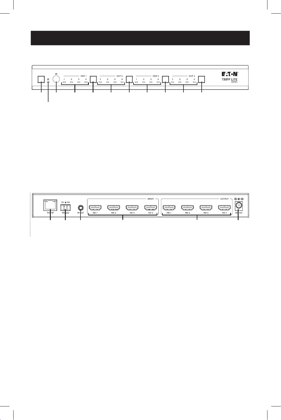
6. Operation Controls and Functions
1
1
2
2
3
3
4
4
4
4
4
4
4
4
5
5
5
5
5
5
5
5
1
Power Button: Short-press to power on the unit. In power-on status, press for
1 second to enter standby status.
2
Power LED: Lights green during normal operation. Lights red during standby
status.
3
IR Window: IR signal receiving window.
4
Signal Source LED: Indicates OUT 1–OUT 4 ports.
5
Input Source Switching Button: Switches between OUT 1–OUT 4 ports.
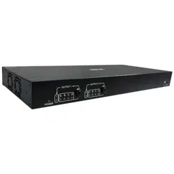
6.2 Rear Panel
6.1 Front Panel
1
TCP/IP: Link port for TCP/IP control connects to an active Ethernet link with an
RJ45 Ethernet cable.
2
RS-232 3-Pin Phoenix Connector: Connects to a PC or control system for serial
port upgrade or RS-232 command control.
3
IR EXT: IR signal receiving port connects to included IR Receiver cable. If the IR
signal receiving window (see 6.1 Front Panel) is blocked or the unit is installed
in a closed area out of infrared line-of-sight, the IR receiver cable can be
connected to this port to receive the IR remote signal.
4
HDMI Input: HDMI signal input ports connect to the signal source devices.
5
HDMI Output: HDMI signal output ports connect to the HDMI displays.
6
DC 12V: Connects to included external power supply.
1
1
2
2
3
3
6
6
4
4
5
5
7
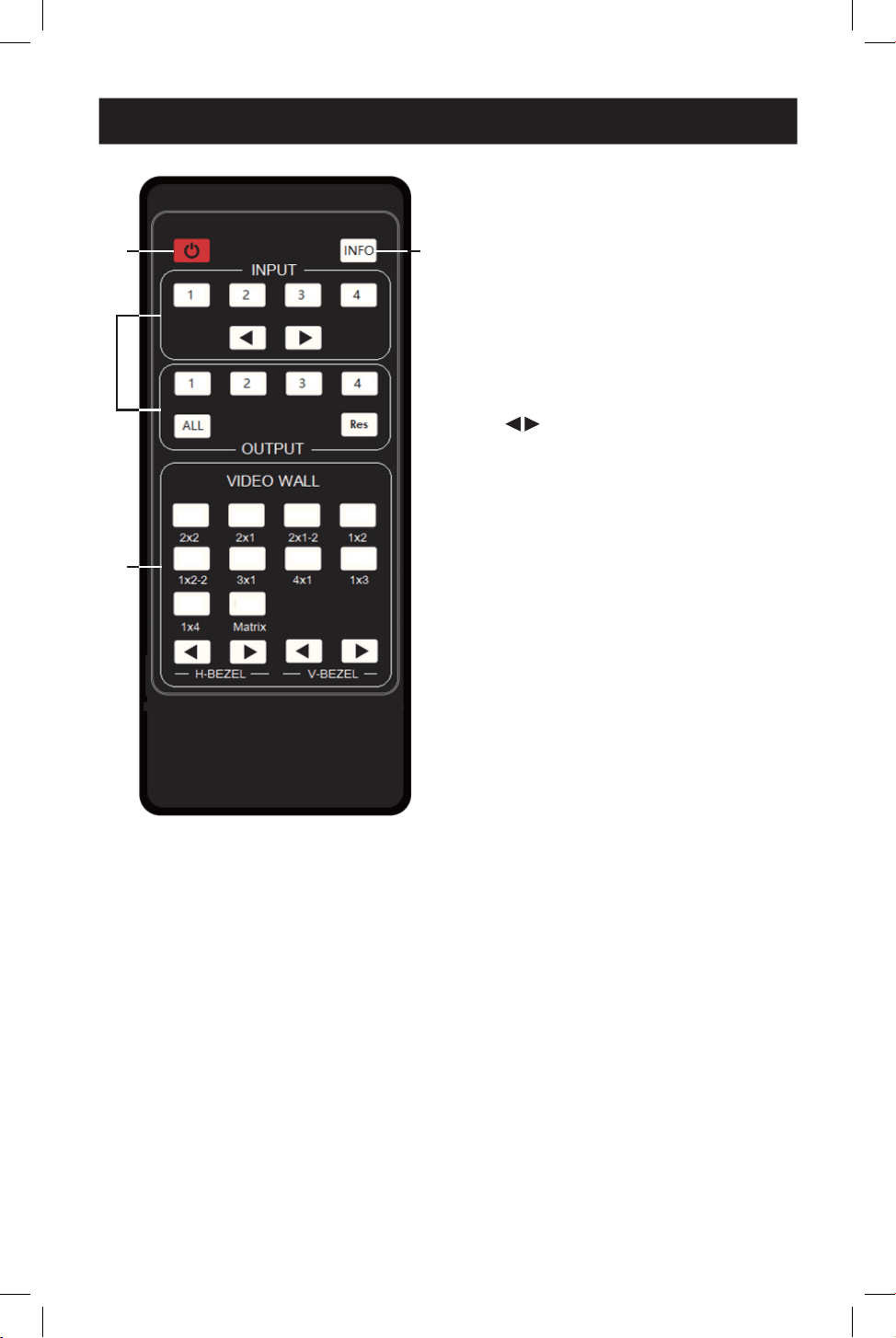
7. IR Remote
1
Power On or Standby: Power on
the device or set it to standby mode.
2
INFO: Displays the serial port baud
rate and IP address in the upper-
right corner of the screen
(information will disappear after 5
seconds).
3
INPUT/OUTPUT
• INPUT 1/2/3/4: Select the signal
input channel.
• : Select the last or next signal
input channel.
• OUTPUT 1/2/3/4: Select the signal
output channel.
• ALL: Select all output channels
simultaneously. For example, when
you press the “ALL” button and
then press INPUT “1” button, the
input “1” source will be output to
all display devices.
Note: After the matrix is turned on, the
ALL key is selected by default. For
example, after turning on the matrix,
press the INPUT 1 button directly, and
the INPUT 1 signal will be output to all
display devices simultaneously.
• Res: Press this button to switch
output channel resolution.
o Matrix Mode: Press OUTPUT
1/2/3/4 or ALL, then press Res
to switch the output resolution
circularly.
o Video Wall Mode: Press Res
directly to switch the output
resolution for four output
channels simultaneously.
• Operation Instruction: You need
to press the OUTPUT button first
and then press the INPUT button
to select the corresponding input
source. For example, press
OUTPUT-X (X means output button
from 1 to 4, including “ALL”
button), then press INPUT-Y (Y
means input button from 1 to 4).
1
1
4
4
2
2
3
3

8
7. IR Remote
8. IR Cable Pin Assignment
4
VIDEO WALL:
• Video Wall Mode Selection:
Press to enter corresponding
mode.
• Source selection for the video wall
group:
o Press OUTPUT 1/2/3/4 or ►
to select the video wall group
first, then press INPUT 1/2/3/4
or to select the input
source.
o Bezel Adjustment: Press of
H-BEZEL / V-BEZEL to adjust the
bezel.
Note: When the angle between the IR receiver and the remote control is ±45°, the transmission
distance is 0–5 meters. When the angle between the IR receiver and the remote control is ±90°,
the transmission distance is 0–8 meters.
IR
RECEIVER
IR
RECEIVER
1
IR Signal
2
Power
3
Grounding
9
9. EDID Management
This HDMI Matrix Switch/Splitter has 12 factory-defined EDID settings, two user-
defined EDID modes and four copy EDID modes. You can select a defined EDID
mode or copy EDID mode to input port through RS-232 control or Web GUI.
RS-232 Control Operation
Connect the HDMI Matrix Switch/Splitter to a PC with a serial cable, then open a
Serial Command tool on the PC to send an ASCII command “s edid in x from z!” to
set EDID. For details, refer to EDID Setting in the ASCII command list of 12. RS-232
Control Command.
Web GUI Operation
Check the EDID management in the Input section of 11. Web GUI User Guide.
The defined EDID setting list of the product is shown as below:
EDID
Mode EDID Description
1 4k2k60_444, stereo audio 2.0
2 4k2k60_444, Dolby/DTS 5.1
3 4k2k60_444, HD audio 7.1
4 4k2k30_444, stereo audio 2.0
5 4k2k30_444, Dolby/DTS 5.1
6 4k2k30_444, HD audio 7.1
7 1080p, stereo audio 2.0
8 1080p, Dolby/DTS 5.1
9 1080p, HD audio 7.1
EDID
Mode EDID Description
10 1920x1200, stereo audio 2.0
11 1360x768, stereo audio 2.0
12 1024x768, stereo audio 2.0
13 user dene1
14 user dene2
15 copy from HDMI output 1
16 copy from HDMI output 2
17 copy from HDMI output 3
18 copy from HDMI output 4

10
10. Video Wall
The HDMI Matrix Switch/Splitter supports 10 categories of display modes as below:
You can select display modes via IR remote, Web GUI or RS-232 commands.
Group 1
Group 2
Group 3
Group 4
11
11. Web GUI User Guide
You can control the HDMI Matrix Switch/Splitter by Web GUI. Before connecting and
logging into the Web GUI, you must obtain the current IP address. TThe default IP
address is 192.168.0.100. You can get the current Matrix IP address in two ways:
• Remote controller: Press “INFO” button on the remote control, and the IP address
will show the upper right corner of the screen.
• RS-232 control: Send the ASCII command “ r ip addr!” through a Serial Command
tool, then you’ll get the feedback information as shown below:
ip address: 192.168.0.100
IP:192.168.0.100 in the above figure is the current Matrix IP address (this IP address
is variable, depending on what the specific machine returns). For the details of
RS-232 control, please refer to 11. RS-232 Control Command.
The HDMI Matrix Switch/Splitter supports connecting and logging into the Web GUI
through PC or MacBook. The specific device connection and setup methods are as
follows:
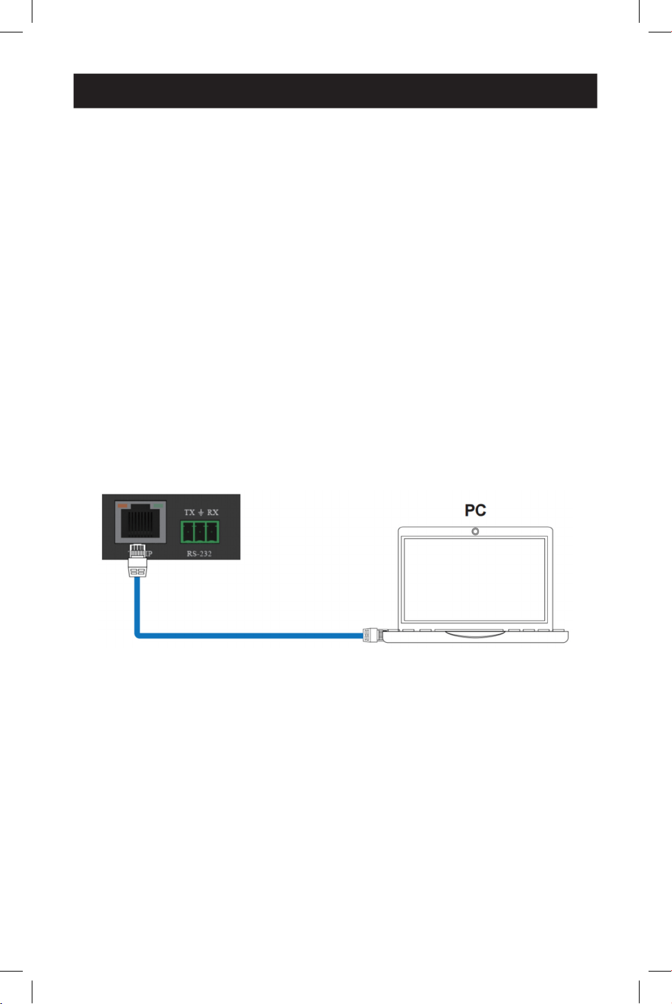
Connect via PC
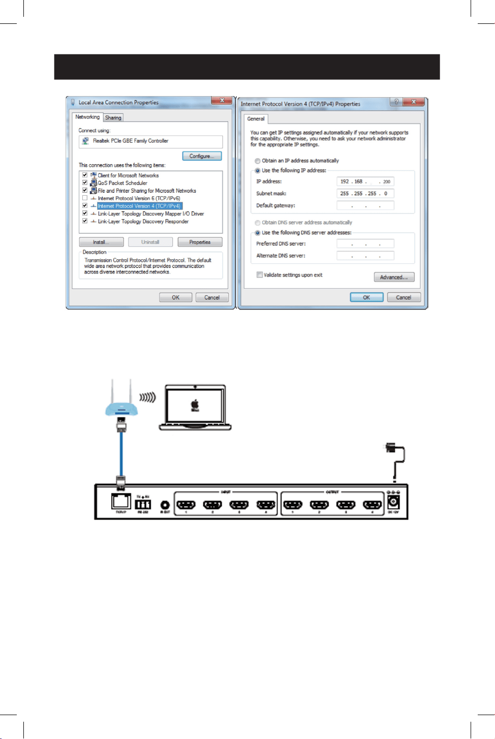
Step 1: Connect the TCP/IP port of the HDMI Matrix Switch/Splitter to a PC with a
UTP cable (as shown in the following figure), and connect the Switch/Splitter’s power
supply to an AC outlet.
Step 2: Modify the PC’s IP address to 192.168.0.xxx, so that it is in the same
network segment as the HDMI Matrix Switch/Splitter. For example, if the Switch/
Splitter’s IP address is 192.168.0.100, the PC’s IP address can be changed to
192.168.0.12. Specific operation steps are shown in the following figures.
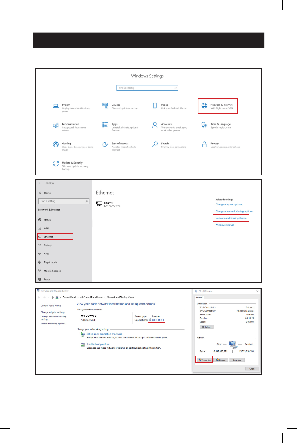
12
11. Web GUI User Guide
First, open Settings in Windows.
13
11. Web GUI User Guide
Connect via MacBook
Step 1: Connect the TCP/IP port of the HDMI Matrix Switch/Splitter to the router
with a UTP cable (as shown in the following figure), and connect the Switch/Splitter’s
power supply to an AC outlet.
Step 2: Connect the router’s wi-fi on the MacBook. Then, modify the MacBooks’s IP
address to 192.168.0.xxx, so that it is in the same network segment as the HDMI
Matrix Switch/Splitter. For example, if the Switch/Splitter’s IP address is
192.168.0.100, the MacBooks’s IP address can be changed to 192.168.0.12.
To change the IP address, select System Settings in the Apple dropdown menu.
Click Network, and then Wi-Fi. Click Details, and then TCP/IP. From there, you will be
able to manually change the MacBook’s IP address.
Router
MacBook
Power Supply
14
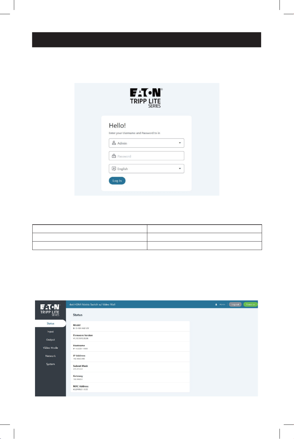
Logging In
Enter the HDMI Matrix Switch/Splitter’s IP address into the PC or MacBook’s web
browser to access the Web GUI page.
Select the language from the drop-down list to choose English or Simple Chinese.
Select the username from the drop-down list and enter the password. The default
passwords are:
Username Password
Admin admin
User user
After entering the password, click the “Log In” button to access the Web GUI main
page.
Status Page
The Status Page provides basic information about the product model, installed
firmware version and network settings of the device.
11. Web GUI User Guide
15
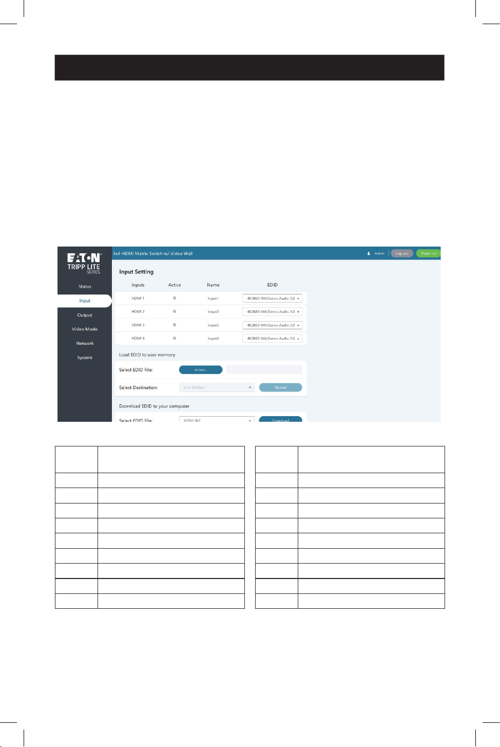
11. Web GUI User Guide
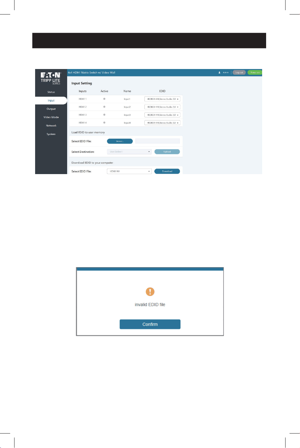
Input Page
You can do the following operations on the Input page:
• Inputs: Input channel of the device.
• Active: Indicates whether the channel is connected to a signal source. When the
input port is connected to the signal, it shows green. Otherwise, it shows gray.
• Name: You can modify the input channel’s name by entering the corresponding
name (max length: 32 characters) in the input box.
• EDID: You can set the current channel’s EDID. Click the drop-down list to select.
• Load EDID to User Memory: Set EDID for the User. Click the “Browse” button,
then select the bin file. If you select the wrong EDID file, there will be a prompt, as
shown in the following figure:
16
11. Web GUI User Guide
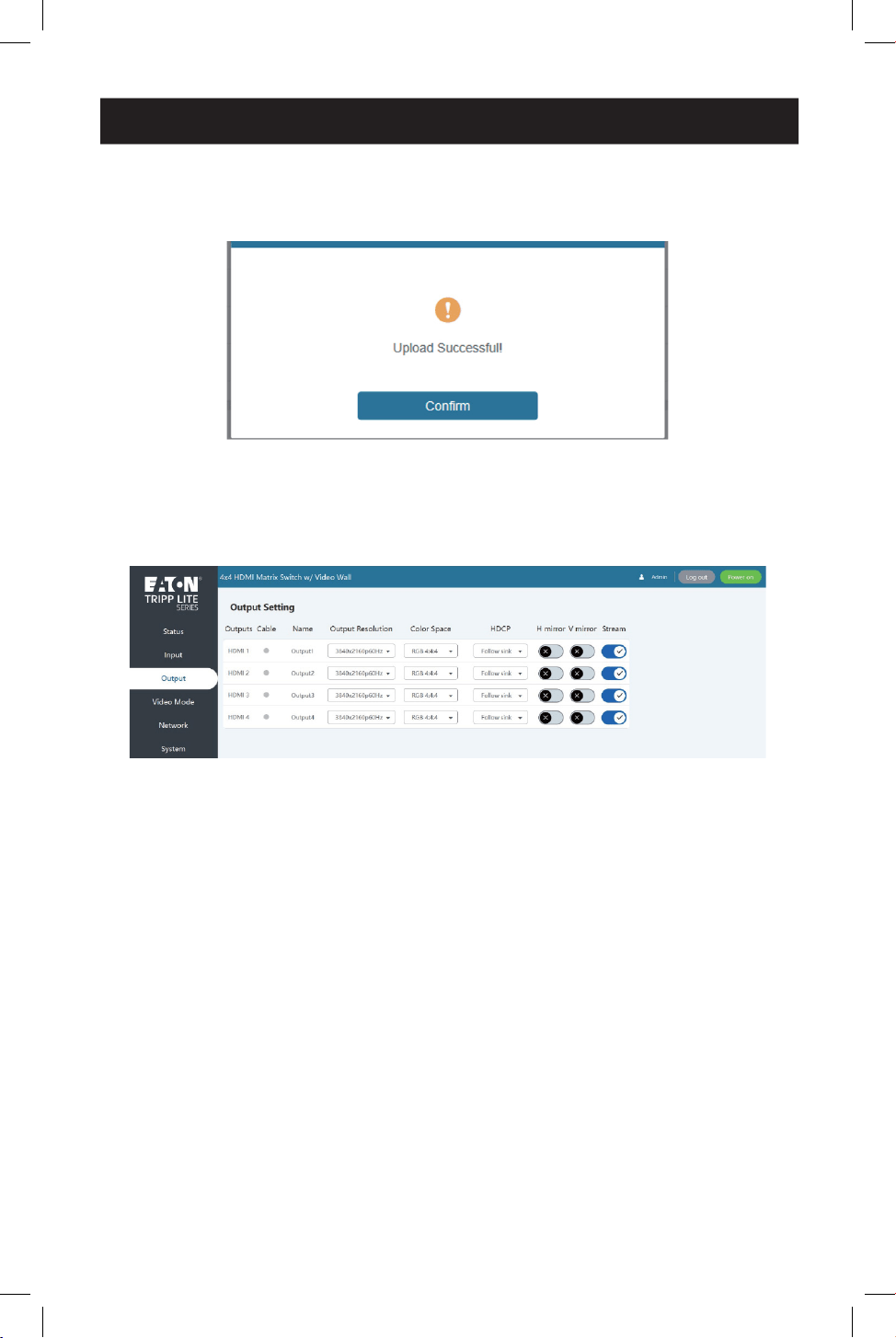
Make sure to select the correct file, then you can check the name of the selected
file. Select “User 1” or “User 2”, then click “Upload”. After successful setting, it will
prompt as follows:
• Download EDID to Your Computer: Click “Select EDID File” in the drop-down
menu to select the corresponding input channel. Then click “Download” to
download the corresponding EDID file.
Output Page
You can do the following operations on the Output page:
• Outputs: Output channel of the device.
• Cable: It indicates the connection status of output ports. When the output port is
connected to the display, it shows green. Otherwise, it shows gray.
• Name: You can modify the output channel’s name by entering the corresponding
name (max length: 32 characters) in the input box.
• Output Resolution: Set the current output resolution mode. Click the drop-
down list to select other resolutions.
• Color Space: Set the color space of the output signal.
• HDCP: Set the HDCP version that the current output port supports.
• H Mirror: Turn on/off the horizontal mirroring of the output signal.
• V Mirror: Turn on/off the vertical mirroring of the output signal.
• Stream: Turn on/off the signal output stream of the output port.
Note: User cannot set each output resolution separately in video wall mode.
17
11. Web GUI User Guide
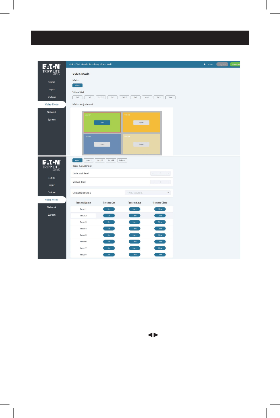
Video Mode Page
You can do the following operations on the Video page:
• Matrix: Click to select the Matrix mode.
• Video Wall: Click to select any video wall mode.
• Matrix/Video Wall Adjustment: Display the input and output information.
• Input Source: Two methods to select the input source:
o Method 1: Drag Input 1/2/3/4/Pattern to any window of Matrix/Video Wall
Adjustment.
o Method 2: Select any window in Matrix/Video Wall Adjustment, then click Input
1/2/3/4/ Pattern in Input Source, or click to select the last or next signal
source.
• Bezel Adjustment: Click +/- to adjust the corresponding Horizontal/Vertical
Bezel (up to 10 levels).
• Output Resolution: Set the resolution of all current output ports. Click the drop-
down list to select.
18
11. Web GUI User Guide
• Preset: Set, save and clear the preset scenario as required, supporting up to 8
presets. You can modify the name of the preset by entering the corresponding
name (max length: 32 characters) in the input box.
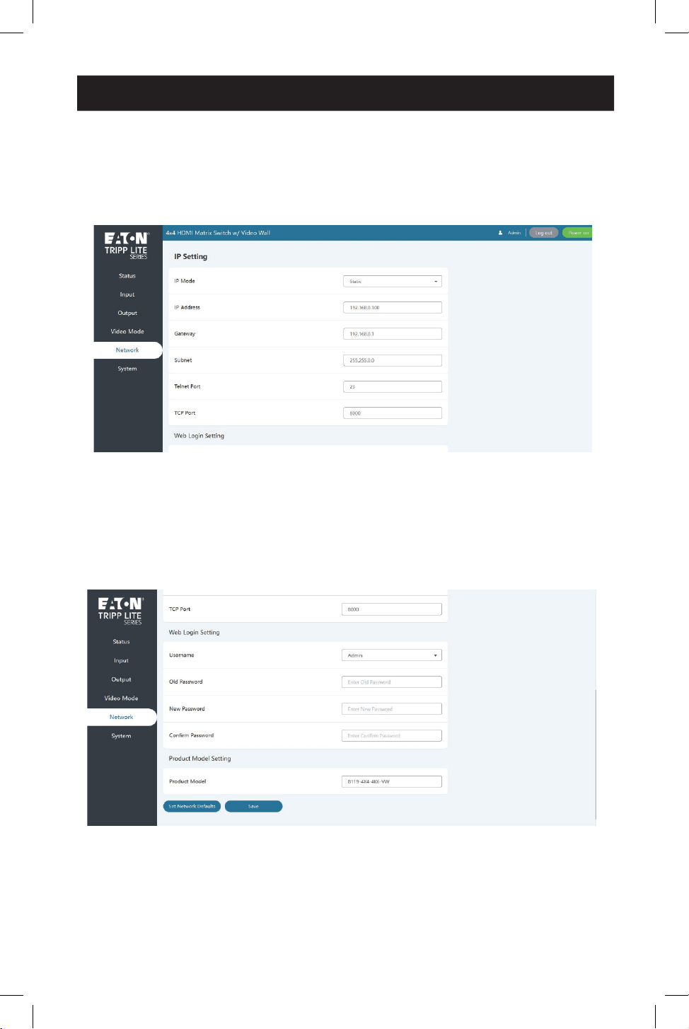
Network Page
You can do the following operations on the Network page:
Modify Network Setting
Modify the IP Mode Address/Gateway/Subnet Mask/Telnet Port as required, and
click “Save” to save the settings. After modification, if the Mode is “Static”, it will
switch to the corresponding IP Address. If the Mode is “DHCP”, it will automatically
search and switch to the IP Address assigned by the router.

19
11. Web GUI User Guide
Modify User Password
Click the “User” button, enter the correct Old Password and New Password, confirm
the New Password, then click “Save”. After successful modification, there will be a
prompt, as shown in the following figure:
Note: Input rules for changing passwords:
• New password can’t be empty.
• New Password can’t be the same as Old Password.
• New Password and Confirm Password must be the same.
Set the Default Network
Click the “Set Network Defaults” button. You will see a prompt, as shown in the
following figure:
20
11. Web GUI User Guide
Click “OK” to search the IP Address again, as shown in the following figure:
After searching is completed, it will switch to the login page, and the default network
setting is completed.
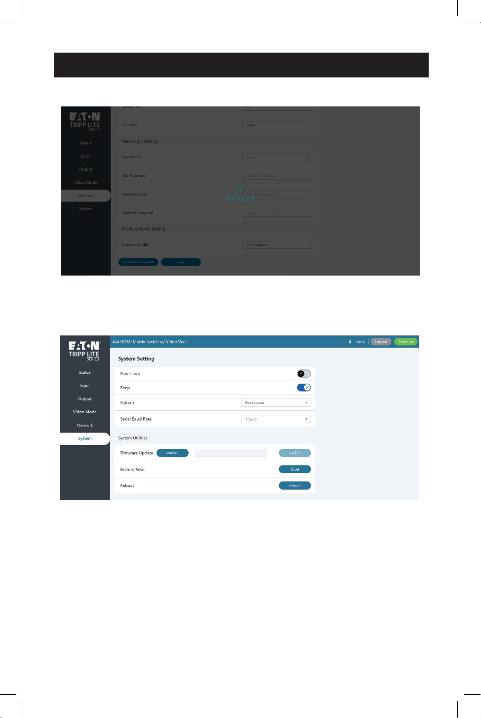
System Page

21
11. Web GUI User Guide
You can do the following operations on the System page:
• Panel Lock: Click to lock/unlock panel buttons. “ON” indicates that panel buttons
are unavailable. “OFF” indicates panel buttons are available.
• Beep: Click to turn the beep on or off.
• Pattern: Click to select one of 6 patterns.
• Serial Baud Rate: Click the value to set the Serial Baud Rate.
• Firmware Update: Click “Browse” to select the update file, then click “Update” to
complete firmware update.
• Factory Reset: You can reset the machine to factory defaults by clicking “Reset”.
• Reboot: You can reboot the machine by clicking “Reboot”.
Note: After reset/reboot, it will switch to the login page.
22
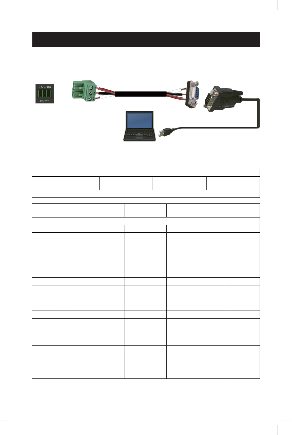
12. RS-232 Control Command
The HDMI Matrix Switch/Splitter supports RS-232 command control. Connect its
RS-232 port to a PC with a 3-pin Phoenix connector cable and an RS-232-to-USB
cable. The connection method is as follows:
Then, open a Serial Command tool on PC to send ASCII command to control the
device. The ASCII command list is shown below.
ASCII Command
Serial port protocol: Baud
rate: 115200 (default)
Data bits: 8 Stop bits: 1 Check bit: 0
x - Parameter 1, y - Parameter 2, z - Parameter 3, ! - Delimiter
Command
Code Function Description Example Feedback
Default
Setting
System Setting
help! Lists all commands help!
r status! Get device current
status
r status! get the unit all status:
power, beep, lock, in/
out connection, video/
audio crosspoint, EDID,
scaler, network status
r type! Get device model r type! 4x4 HDMI seamless
matrix
r fw version! Get rmware version r fw version! mcu fw version x.xx.xx
s power z! Power on/o the
device, z=0~1 (z=0
power o, z=1 power
on)
s power 1! power on
system initializing...
initialization nished!
mcu fw version x.xx.xx
r power! Get current power state r power! power on/power o
s beep z! Enable/disable buzzer
function, z=0~1(z=0
beep o, z=1 beep on)
s beep 1! beep on/beep o beep on
r beep! Get buzzer state r beep! beep on/beep o beep on
s lock z! Lock/unlock front panel
button, z=0~1(z=0 lock
o,z=1 lock on)
s lock 1! panel button lock on
panel button lock o
panel button
lock o
r lock! Get panel button lock
state
r lock! panel button lock on/
o
TX
Ground
RX
3-Pin Phoenix
Connector
RS-232
RS-232 to USB Cable

23
12. RS-232 Control Command
Command
Code Function Description Example Feedback
Default
Setting
s reboot! Reboot the device s reboot! reboot…
system initializing...
initialization nished!
mcu fw version x.xx.xx
s reset! Reset to factory
defaults
s reset! reset to factory defaults
system initializing...
initialization nished!
mcu fw version x.xx.xx
s save
preset z!
Save preset z scenarios
(z=1~8)
s save preset 1! save to preset 1!
s recall
preset z!
Call saved preset z
scenarios (z=1~8)
s recall preset 1! recall from preset 1
s clear
preset z!
Clear preset z scenarios
(z=1~8)
s clear preset 1! clear preset 1!
r preset z! Get preset z
information (z=1~8)
r preset 1! video/audio crosspoint
Output Setting
s in x av
out y!
Set input x to output
y~x=1~4~ y=0~4(0=all)
s in 1 av out 2! input 1 -> output 2 ptp
r av out y! Get output y signal
status y=0~4(0=all)
r v out 0! input 1 -> output 1
input 2 -> output 2
……
input 4 -> output 4
s output y
res x!
Set output y resolution
(y=0~4, x=1~16)
y=0. output all y=1.
output 1
y=2. output 2
y=3. output 3
y=4. output 4
1. 4096x2160p60,
2. 4096x2160p50,
3. 3840x2160p60,
4. 3840x2160p50,
5. 3840x2160p30,
6. 1920x1080p60,
7. 1920x1080p50,
8. 1920x1080i60,
9.1920x1080i50,
10. 1920x1200p60rb,
11.1360x768p60,
12.1280x800p60,
13.1280x720p60,
14.1280x720p50,
15.1024x768p60,
16. auto

24
12. RS-232 Control Command
Command
Code Function Description Example Feedback
Default
Setting
r output y
res!
Get output y
resolution(y=0~4) y=0.
output all
y=1. output 1
y=2. output 2
y=3. output 3
y=4. output 4
s output 1 csc 1! output 1 resolution:
3840x2160p60
s output y
csc x!
Set output y color
space (y=0~4, x=1~4)
y=0. output all y=1.
output 1
y=2. output 2
y=3. output 3
y=4. output 4 x=1.
rgb444 x=2. ycbcr444
x=3. ycbcr422 x=4.
ycbcr420
s output 1 csc 1! output 1 csc: rgb444 rgb444
r output y
csc!
Get output y color
space status. (y=0~4)
y=0. output all y=1.
output 1
y=2. output 2
y=3. output 3
y=4. output 4
r output 1 csc! output 1 csc: rgb444
s output y
hdcp x!
Set output hdcp(y=0~4,
x=1~4) y=0. output all
y=1. output 1
y=2. output 2
y=3. output 3
y=4. output 4
x=1. hdcp 1.4
x=2. hdcp 2.2 x=3.
follow sink x=4. follow
source
s output 1 hdcp
1!
output 1 hdcp:
hdcp 1.4
hdcp1.4
r output y
hdcp!
Get output y hdcp
status.(y=0~4) y=0.
output all
y=1. output 1
y=2. output 2
y=3. output 3
y=4. output 4
r output 1 hdcp! output 1 hdcp:
hdcp 1.4
s output y
hmirror x!
Set output y h
mirror(y=0~4,x=0,1)
y=0. output all
y=1. output 1
y=2. output 2
y=3. output 3
y=4. output 4 x=0. h
mirror o x=1. h mirror
on
s output 1
hmirror 1!
output1 h mirror on output 1 h
mirror o
output 2 h
mirror o
output 3 h
mirror o
output 4 h
mirror o

25
12. RS-232 Control Command
Command
Code Function Description Example Feedback
Default
Setting
s output y
vmirror x!
set output y v
mirror(y=0~4,x=0,1)
y=0. output all
y=1. output 1
y=2. output 2
y=3. output 3
y=4. output 4 x=0. v
mirror o x=1. v mirror
on
s output 1
vmirror 0!
output1 v mirror o output 1 v
mirror o
output 2 v
mirror o
output 3 v
mirror o
output 4 v
mirror o
r output y
mirror!
Get output y mirror
status(y=0~4) y=0.
output all
y=1. output 1
y=2. output 2
y=3. output 3
y=4. output 4
r output 0
mirror!
output 1 h mirror on, v
mirror o
output 2 h mirror on, v
mirror o
output 3 h mirror on, v
mirror o
output 4 h mirror on, v
mirror o
s output y
stream x!
Set output y stream
enable/disable (y=0~4,
x=0~1)
y=0. output all y=1.
output 1
y=2. output 2
y=3. output 3
y=4. output 4
x=0. stream disable
x=1. stream enable
s output 1
stream 1!
output 1 stream:
enable
enable
r output y
stream!
Get output y stream
status. (y=0~4)
y=0. output all y=1.
output 1
y=2. output 2
y=3. output 3
y=4. output 4
r output 1
stream!
output 1 stream:
enable
s output
bg x!
Set output no signal
background display
mode (x=1~6)
x=1. black screen x=2.
blue screen x=3. color
bar x=4. gray scale x=5.
cross
x=6. cross hatch
s output bg 1! output background:
black screen
black screen
r output bg! Get output no signal
background display
mode
r output bg! output background:
black screen

26
Command
Code Function Description Example Feedback
Default
Setting
EDID Setting
s edid in x
from z!
Set hdmi input x edid
mode (x=0~4,z=1~18)
x=0. all input x=1.
input1 x=2.
input2 x=3.
input3 x=4.
input4 z=1.
4k2k60_444,stereo
audio 2.0 z=2.
4k2k60_444,dolby/dts
5.1 z=3. 4k2k60_444,hd
audio 7.1 z=4.
4k2k30_444,stereo
audio 2.0 z=5.
4k2k30_444,dolby/dts
5.1 z=6.
4k2k30_444,hd audio
7.1 z=7. 1080p,stereo
audio 2.0 z=8.
1080p,dolby/dts 5.1
z=9.
1080p,hd audio 7.1
z=10.
1920x1200, stereo
audio 2.0 z=11.
1360x768, stereo audio
2.0 z=12.
1024x768, stereo audio
2.0 z=13.
user dene1 z=14.
user dene2 z=15.
copy from hdmi output
1 z=16.
copy from hdmi output
2 z=17.
copy from hdmi output
3 z=18.
copy from hdmi output
4
s edid in 1 from
1!
s edid in 0 from
1!
input 2 edid:1080p,
stereo audio 2.0
all inputs edid:1080p,
stereo audio 2.0
4k2k60_444,
stereo audio
2.0
r edid in x! Get input x edid
mode(x=0~4) x=0. all
input
x=1. input1 x=2. input2
x=3. input3 x=4. input4
r edid in 0! input 1 edid:
4k2k60_444, stereo
audio 2.0
input 2 edid:
4k2k60_444, stereo
audio 2.0
input 3 edid:
4k2k60_444, stereo
audio 2.0
input 4 edid:
4k2k60_444,
stereo audio 2.0
12. RS-232 Control Command

27
12. RS-232 Control Command
Command
Code Function Description Example Feedback
Default
Setting
Video Wall Setting
s tw mode
x!
Set tv wall display
mode(x=1~10) x=1. 2x2
mode
x=2. 2x1 mode x=3.
2x1-2 mode x=4. 1x2
mode x=5. 1x2-2 mode
x=6. 3x1 mode x=7. 4x1
mode x=8. 1x3 mode
x=9. 1x4 mode x=10.
matrix mode
s tw mode 1! tv wall mode: 2x2 tv wall
mode: 2x2
r tw mode! Get tv wall display
mode
r tw mode! tv wall mode: 2x2
s tw h bezel
x!
set tv wall horizontal
bezel (x=0~10,+,-)
s tw h bezel 0! tv wall horizontal bezel:
0
tv wall
horizontal
bezel: 0
r tw h bezel! Get tv wall row bezel r tw h bezel! tv wall horizontal bezel:
0
s tw v bezel
x!
Set tv wall vertical bezel
(x=0~10,+,-)
s tw v bezel 0! tv wall vertical bezel: 0 tv wall
vertical
bezel: 0
r tw v bezel! Get tv wall vertical bezel r tw v bezel! tv wall vertical bezel: 0
s tw group y
i nput x!
Set tv wall group y
display which source
input(y=0~4, x=1~4)
y=0. tv wall group all
y=1. tv wall group 1 y=2.
tv wall group 2 y=3. tv
wall group 3 y=4. tv wall
group 4
x=1. hdmi input 1 x=2.
hdmi input 2 x=3.
hdmi input 3 x=4. hdmi
input 4
s tw group 1
input 1!
tv wall group 1 input:
hdmi input 1
tv wall group
1 input:
hdmi input 1
r tw group y
source!
Get tv wall group y
display which source
input(y=0~4)
y=0. tv wall group all
y=1. tv wall group 1 y=2.
tv wall group 2 y=3. tv
wall group 3 y=4. tv wall
group 4
r tw group 0
source!
tv wall group 1 input:
hdmi input 1
tv wall group 2 input:
hdmi input 2
tv wall group 3 input:
hdmi input 3
tv wall group 4 input:
hdmi input 4

28
12. RS-232 Control Command
Command
Code Function Description Example Feedback
Default
Setting
s tw res x! Set tv wall resolution
(x=1~15) 1.
4096x2160p60,
2. 4096x2160p50,
3. 3840x2160p60,
4. 3840x2160p50,
5. 3840x2160p30,
6. 1920x1080p60,
7. 1920x1080p50,
8. 1920x1080i60,
9.1920x1080i50,
10. 1920x1200p60rb,
11.1360x768p60,
12.1280x800p60,
13.1280x720p60,
14.1280x720p50,
15.1024x768p60,
s tw res 3! tv wall resolution:
3840x2160p60
3840x2160
p60
r tw res! Get tv wall resolution r tw res! tv wall resolution:
3840x2160p60
3840x2160
p60
Network Setting
r ipcong! Get the current ip
conguration
r ipcong ! ip mode: static ip:
192.168.0.100
subnet mask:
255.255.255.0
gateway: 192.168.0.1
tcp/ip port=8000 telnet
port=23
mac address:
00:1c:91:03:80:01
r mac addr! Get network mac
address
r mac addr! mac address:
00:1c:91:03:80:01
s ip mode z! Set network ip mode to
static ip or dhcp,z=0~1
(z=0 static, z=1 dhcp)
s ip mode 0! set ip mode:static.
(please use "s net
reboot!" command
or repower device to
apply new cong!)
r ip mode! Get network ip mode r ip mode! ip mode: static
s ip addr
xxx.xxx.xxx.
xxx!
Set network ip address s ip addr
192.168.0.100!
set ip address:
192.168.0.100
(please use "s net
reboot!" command
or repower device to
apply new cong!) dhcp
on, device can't cong
static address, set dhcp
o rst.
r ip addr! Get network ip address r ip addr! ip address:
192.168.0.100

29
12. RS-232 Control Command
Command
Code Function Description Example Feedback
Default
Setting
s subnet
xxx.xxx.xxx.
xxx!
Set network subnet
mask
s subnet
255.255.255.0!
set subnet mask:
255.255.255.0
(please use "s net
reboot!" command
or repower device to
apply new cong!) dhcp
on, device can't cong
subnet mask, set dhcp
o rst.
r subnet! Get network subnet
mask
r subnet! subnet mask:
255.255.255.0
s gateway
xxx.xxx.xxx.
xxx!
Set network gateway s gateway
192.168.0.1!
set gateway:
192.168.0.1
(please use "s net
reboot!" command
or repower device to
apply new cong!) dhcp
on, device can't cong
gateway, set dhcp o
rst.
r gateway! Get network gateway r gateway! gateway:192.168.0.1
s tcp/ip
port x!
Set network tcp/ip port
(x=1~65535)
s tcp/ip port
8000!
set tcp/ip port:8000
r tcp/ip
port!
Get network tcp/ip port r tcp/ip port! tcp/ip port:8000
s telnet
port x!
Set network telnet
port(x=1~65535)
s telnet port 23! set telnet port:23
r telnet
port!
Get network telnet port r telnet port! telnet port:23
s net
reboot!
Reboot network
modules
s net reboot! network reboot…
ip mode: static ip:
192.168.0.100
subnet mask:
255.255.255.0
gateway: 192.168.0.1
tcp/ip port=8000 telnet
port=10
mac address:
00:1c:91:03:80:01
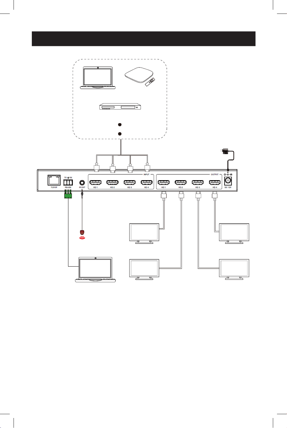
30
13. Application Example
Cable/Satellite Box
Laptop or PC
Laptop or PC
Display 1
IR Receiver
Display 4
Display 2 Display 3
Power Supply
Media Server or Blu-ray Player

31
Warranty
3-YEAR LIMITED WARRANTY
We warrant our products to be free from defects in materials and workmanship for a period of three
(3) years from the date of initial purchase. Our obligation under this warranty is limited to repairing or
replacing (at its sole option) any such defective products. Visit Tripplite.Eaton.com/support/product-returns
before sending any equipment back for repair. This warranty does not apply to equipment which has been
damaged by accident, negligence or misapplication or has been altered or modied in any way.
EXCEPT AS PROVIDED HEREIN, WE MAKE NO WARRANTIES, EXPRESS OR IMPLIED, INCLUDING WARRANTIES
OF MERCHANTABILITY AND FITNESS FOR A PARTICULAR PURPOSE. Some states do not permit limitation or
exclusion of implied warranties; therefore, the aforesaid limitation(s) or exclusion(s) may not apply to the
purchaser.
EXCEPT AS PROVIDED ABOVE, IN NO EVENT WILL WE BE LIABLE FOR DIRECT, INDIRECT, SPECIAL,
INCIDENTAL OR CONSEQUENTIAL DAMAGES ARISING OUT OF THE USE OF THIS PRODUCT, EVEN IF
ADVISED OF THE POSSIBILITY OF SUCH DAMAGE. Specically, we are not liable for any costs, such as lost
prots or revenue, loss of equipment, loss of use of equipment, loss of software, loss of data, costs of
substitutes, claims by third parties, or otherwise.
FCC Notice, Class B
This device complies with part 15 of the FCC Rules. Operation is subject to the following two conditions: (1)
This device may not cause harmful interference, and (2) this device must accept any interference received,
including interference that may cause undesired operation.
Note: This equipment has been tested and found to comply with the limits for a Class B digital device,
pursuant to part 15 of the FCC Rules. These limits are designed to provide reasonable protection against
harmful interference in a residential installation. This equipment generates, uses and can radiate radio
frequency energy and, if not installed and used in accordance with the instructions, may cause harmful
interference to radio communications. However, there is no guarantee that interference will not occur in
a particular installation. If this equipment does cause harmful interference to radio or television reception,
which can be determined by turning the equipment o and on, the user is encouraged to try to correct the
interference by one or more of the following measures:
• Reorient or relocate the receiving antenna.
• Increase the separation between the equipment and receiver.
• Connect the equipment into an outlet on a circuit dierent from that to which the receiver is connected.
• Consult the dealer or an experienced radio/TV technician for help.
Any changes or modications to this equipment not expressly approved by Eaton could void the user’s
authority to operate this equipment.
Eaton has a policy of continuous improvement. Specications are subject to change without notice.