1
Owner’s Manual
Español 19
Français 36
Deutsch 53
Italiano 70
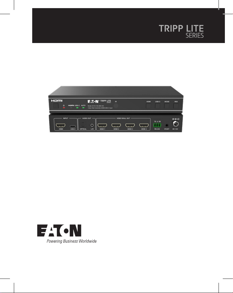
Model:
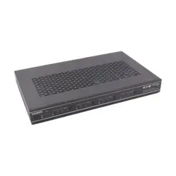
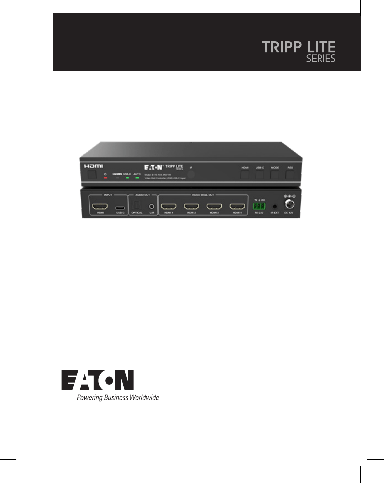
B119-1X4-4K6-VW
Video Wall Controller – 4K
60 Hz, HDMI/USB-C Input,
4x HDMI Output
Purchased product may differ from image.

2
Table of Contents
1. Safety Instructions 3
2. Introduction 3
3. Product Features 4
4. Package Contents 4
5. Specifications 5
6. Operation Controls and Functions 7
7. IR Remote 9
8. IR Cable Pin Assignment 10
9. Video Wall 10
10. RS-232 Control Command 11
11. Application Example 16
12. Warranty 17

3
1. Safety Instructions
2. Introduction
Thank you for purchasing the B119-1X4-4K6-VW. For optimum performance and
safety, please read these instructions carefully before connecting, operating or
adjusting this product. Please keep this manual for future reference.
Surge Protection Device Recommended
This product contains sensitive electrical components that may be damaged by
electrical spikes, surges and other power interruptions. Use of surge protection
systems is highly recommended in order to protect and extend the life of your
equipment.
The Video Wall Controller is designed to capture, convert, route and distribute all
video signal formats to a video wall.
It features HDMI and USB-C input with resolution up to 4K @ 60 Hz (4:4:4) and 4
HDMI outputs. It supports multiple video wall modes to be set for video output.
Furthermore, optical audio and L/R analog audio de-embedding output are also
supported.
You can control the Video Wall Controller using front-panel buttons, the included
IR remote or RS-232 commands.

4
3. Product Features
4. Package Contents
• Supports both HDMI and USB-C input with 4K @ 60 Hz resolutions and 4:4:4
color
• Supports 8 video wall splicing modes: 1x1, 2x1, 3x1, 4x1, 1x2, 1x3, 1x4, 2x2
• HDCP 2.2 and DP 1.2a compliant
• Supports video bandwidth up to 18 Gbps
• Supports optical audio and L/R analog audio de-embedding output
• Supports image 180° rotation, convenient for ceiling installation
• Supports bezel adjustment for the splicing edge
• Advanced EDID management
• Control via front-panel buttons, IR remote or RS-232 commands
• Simple plug-and-play installation with no settings or software required
• 1x4 Video Wall Controller
• External Power Supply
• 12V 1A Locking Power Plug (AS/NZS 3112 Australia, BS 1363 U.K., CEE 7/16
Schuko, NEMA 1-15P North America)
• IR Remote
• 5V IR Receiver Cable, 5 ft. (1.5 m)
• 3-Pin 3.81 mm Phoenix Connector
• (4) KM 3x4 Machine Screws
• (2) Mounting Ears
• User Documentation
5
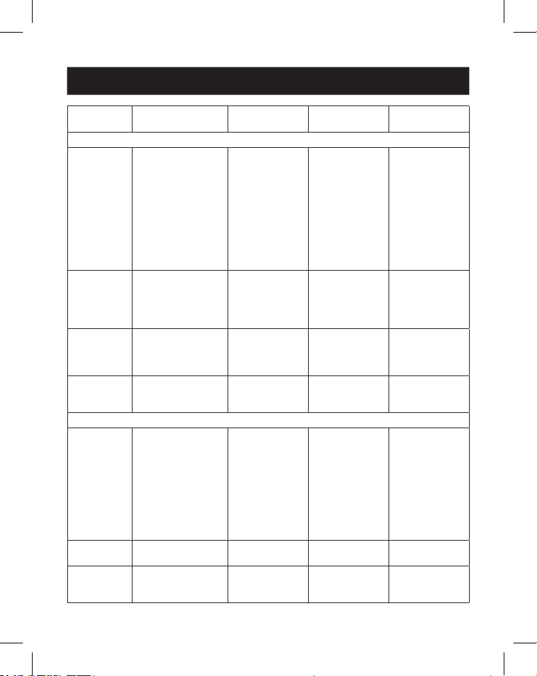
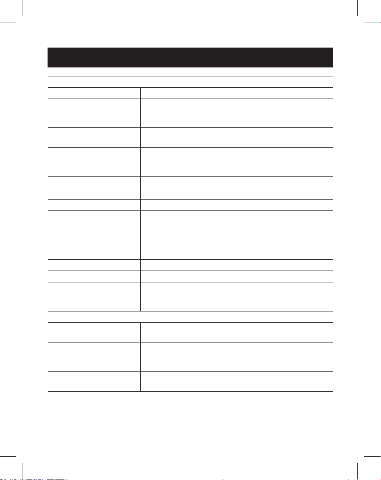
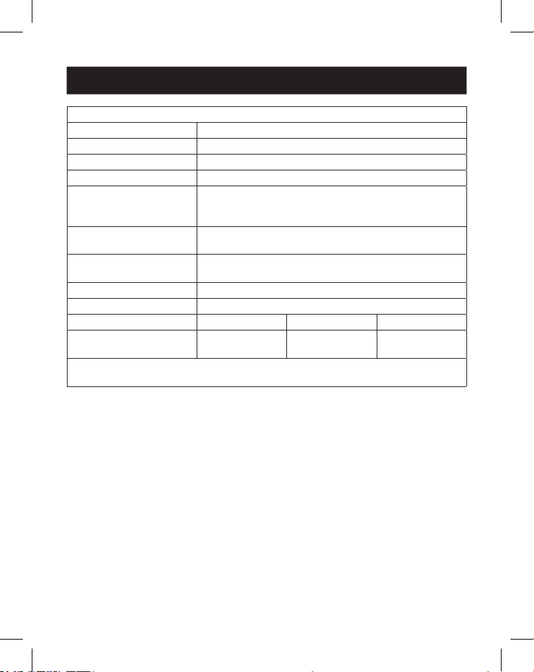
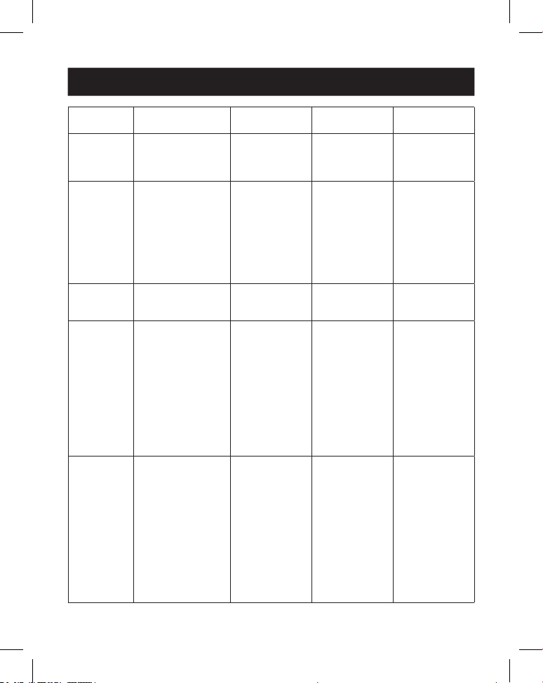
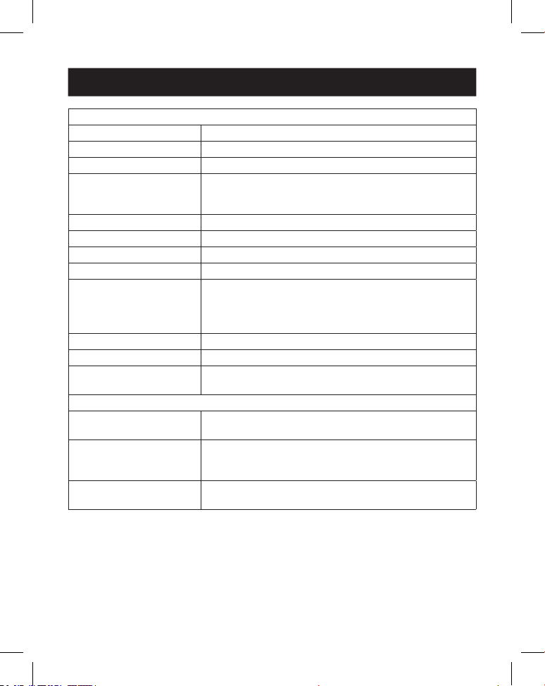
5. Specifications
Technical
HDMI Compliance HDMI 2.0b
HDCP Compliance HDCP 2.2
Video Bandwidth 18 Gbps
Video Resolution Input: up to 4K @ 60 Hz 4:4:4
Output: 720p @ 60 Hz, 1080p @ 60 Hz, 4K @ 30 Hz,
1024x768p @ 60 Hz
Color Space RGB, YCbCr_4:4:4, YCbCr_4:2:2, YCbCr_4:2:0
Color Depth 8/10/12 bit
IR Level 5Vp-p
IR Frequency 38 kHz
Audio Formats HDMI IN/OUT: LPCM 2.0/5.1, Dolby Digital/Plus/EX,
DTS, DTS-EX, DTS-96/24
L/R OUT: PCM 2.0
SPDIF (Optical): Dolby Digital/Plus, DTS 5.1, PCM 2.0
Audio Latency No Latency
Video Latency No Latency
ESD IEC 61000-4-2:
±8kV (Air-gap discharge), ±4kV (Contact discharge)
Connection
Input Ports 1 × HDMI [Type A, 19-pin female]
1 × USB-C [Type C, 24-pin female]
Output Ports 4 × HDMI [Type A, 19-pin female]
1 × Optical Audio [S/PDIF]
1 × L/R Audio [RCA]
Control Ports 1 × RS-232 [3-pin 3.81mm Phoenix Connector]
1 × IR EXT [3.5 mm, Stereo Mini-Jack]
6
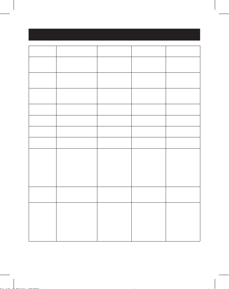
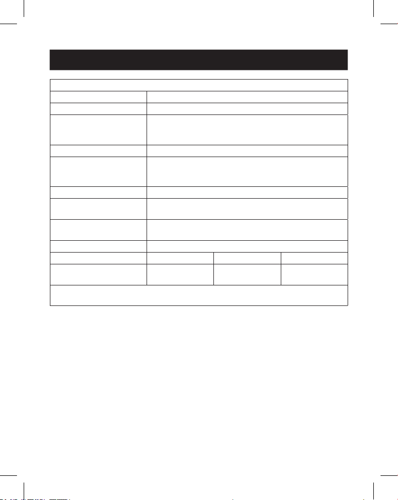
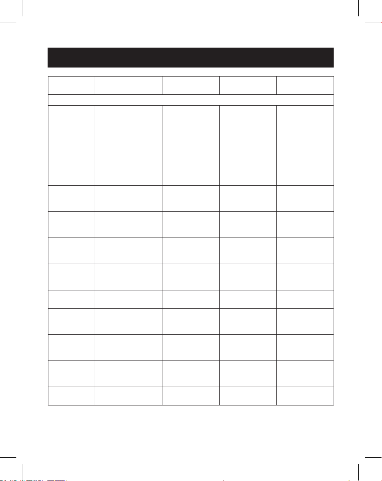
5. Specifications
Mechanical
Housing Metal
Color Black
Dimensions (H x W x D) 1.2 x 8.7 x 3.9 in. / 30 x 220 x 100 mm
Weight 1.3 lb. / 590 g
Power Supply Input: AC 100–240V, 50/60 Hz
Output: DC 12V 1A
(US/EU Standard, CE/FCC/UL Certied)
Power Consumption 5.5W (Max)
Operating Temperature 32° - 104°F / 0° - 40°C
Storage Temperature -4° - 140°F / -20° - 60°C
Relative Humidity 20% - 90% RH (Non-Condensing)
Video Resolution 4K @ 60 Hz 4K @ 24 Hz 1080p @ 60 Hz
HDMI Cable Length
(HDMI In/Out)
26 ft. / 8 m 32 ft. / 10 m 49 ft. / 15 m
The use of “Premium High-Speed HDMI” cable is highly recommended.
7
6. Operation Controls and Functions
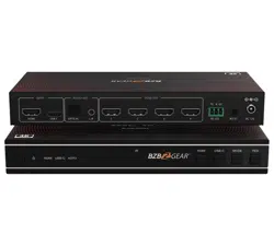
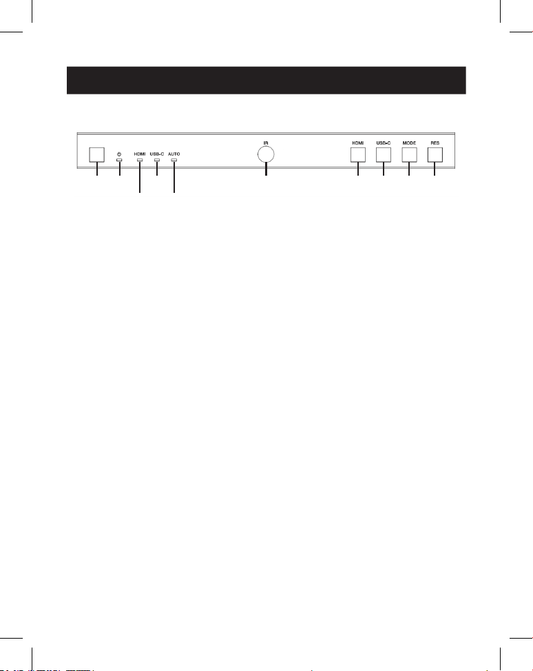
6.1 Front Panel
1
1
2
2
4
4
6
6
7
7
9
9
8
8
J
J
3
3
5
5
1
Power Button: Press to power on the unit in shutdown/standby status. In
power-on status, press for 2 to 3 seconds to enter standby status.
2
Power LED: Lights green during normal operation. Lights red during standby
status.
3
HDMI LED: Lights green when HDMI input is selected.
4
USB-C LED: Lights green when USB-C input is selected.
5
Auto LED: Lights green when auto-switching is enabled.
6
IR Window: IR signal receiving window.
7
HDMI Button: Press to select HDMI input channel.
8
USB-C Button: Press to select USB-C input channel.
9
Mode Button: Press to choose one of the 8 splicing modes.
J
RES Button: Press to choose one of the 4 HDMI output resolutions.

8
6. Operation Controls and Functions
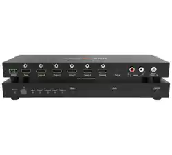
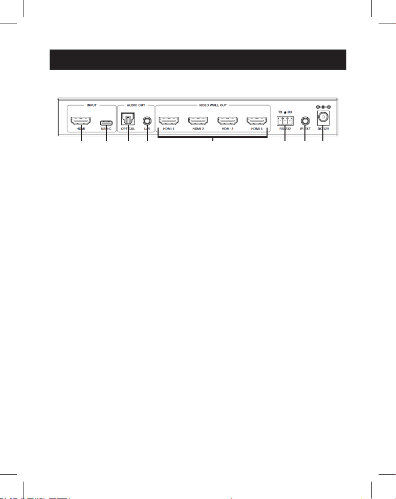
6.2 Rear Panel
1
1
2
2
3
3
4
4
5
5
7
7
6
6
8
8
1
HDMI Input: HDMI signal input port connects to an HDMI source device.
2
USB-C Input: USB-C signal input port connects to a USB-C source device.
3
Optical Audio Out: Connects to an optical audio output device, such as an
audio amplifier.
4
L/R Audio Out: Connects to an analog audio output device, such as a
speaker.
5
Video Wall Out (HDMI 1–4): HDMI signal output ports connect to HDMI
displays.
6
RS-232 3-Pin Phoenix Connector: Connects to a PC or control system for
serial port upgrade or RS-232 command control.
7
IR EXT: IR signal receiving port connects to included IR Receiver cable. If the IR
signal receiving window (see 6.1 Front Panel) is blocked or the unit is
installed in a closed area out of infrared line-of-sight, the IR receiver cable can
be connected to this port to receive the IR remote signal.
8
DC 12V: Connects to included external power supply.

9
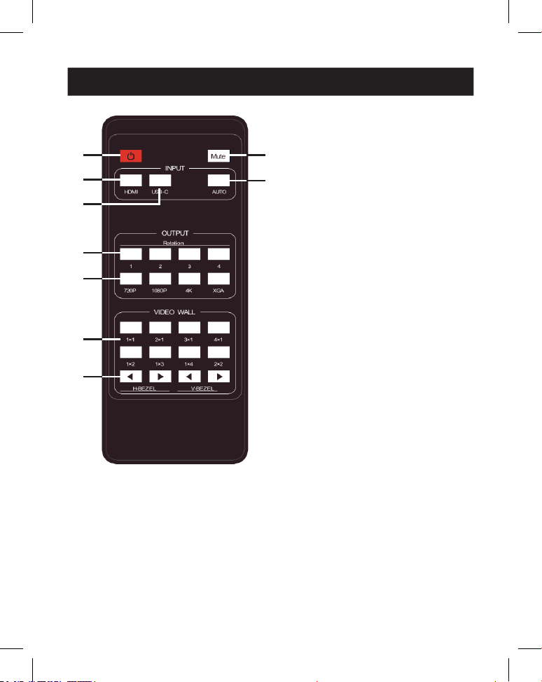
7. IR Remote
1
Power On or Standby: Press to
power on the device or set it to
standby mode.
2
Mute: Press to turn off or on the
audio output, including HDMI,
optical and L/R audio.
3
HDMI: Press to select HDMI
input channel.
4
USB-C: Press to select USB-C
input channel.
5
AUTO: Press to disable or enable
the input auto-switching.
6
Rotation 1/2/3/4: Press to
switch rotation angle between 0˚
and 180˚ for the corresponding
output channel.
7
Resolution 720P/1080P/4K/
XGA: Press to switch the
resolution for the 4 output
channels at the same time.
8
VIDEO WALL MODE: There are 8
splicing modes: 1x1, 2x1, 3x1,
4x1, 1x2, 1x3, 1x4, 2x2. Press to
select the display mode.
9
H/V-BEZEL: Press to adjust the
bezels of the splicing images.
1
1
3
3
4
4
6
6
7
7
8
8
9
9
2
2
5
5

10
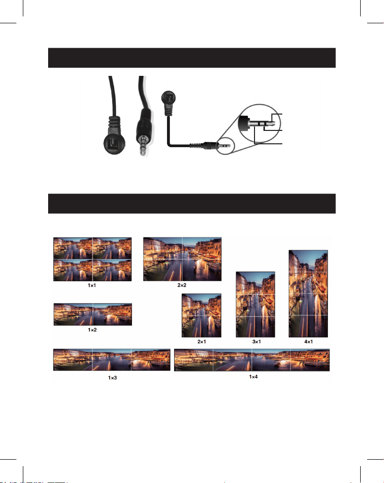
8. IR Cable Pin Assignment
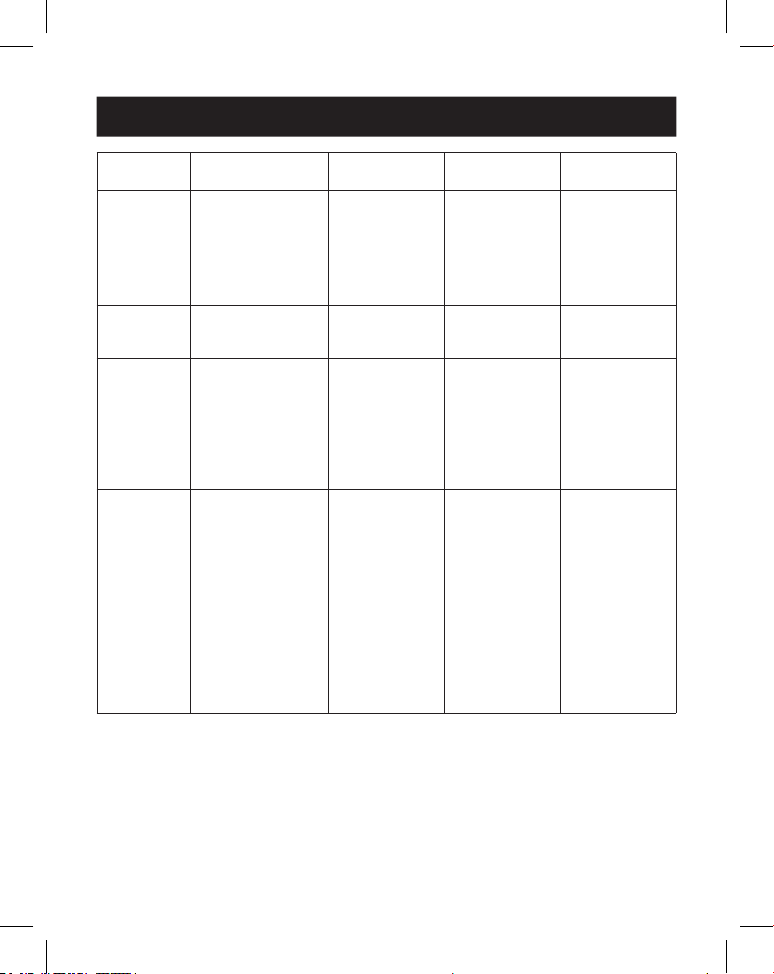
9. Video Wall
IR RECEIVER IR RECEIVER
1
IR Signal
2
Power
3
Grounding
Video wall supports eight splicing modes as below:
You can set display modes via front-panel buttons, IR remote or RS-232
commands.
Note: In video wall mode (except 1x1), only the screens that are selected to perform video wall
splicing will display images, and their bezel can be adjusted.

11
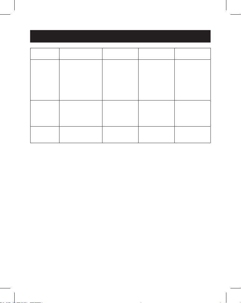
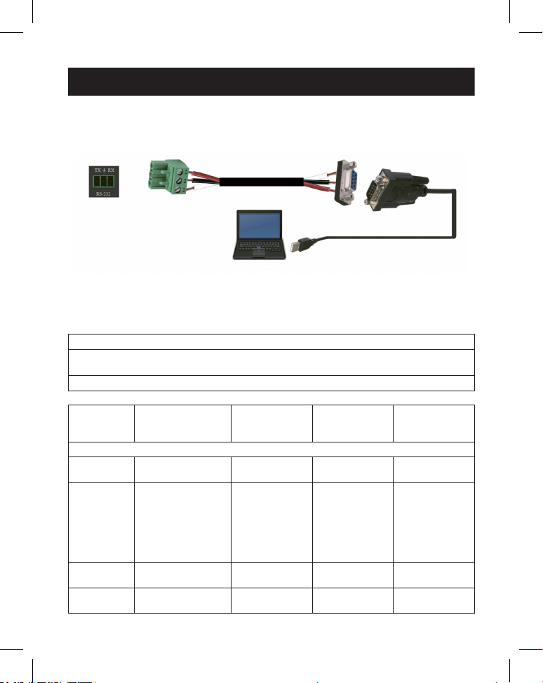
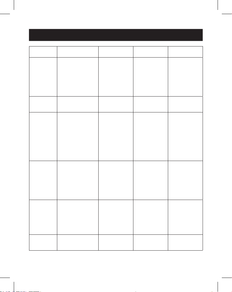
10. RS-232 Control Command
The Video Wall Controller supports RS-232 command control. Connect its RS-232
port to a PC with a 3-pin Phoenix connector cable and an RS-232-to-USB cable.
The connection method is as follows.
Then, open a Serial Command tool on PC to send ASCII command to control the
device. The ASCII command list is shown below.
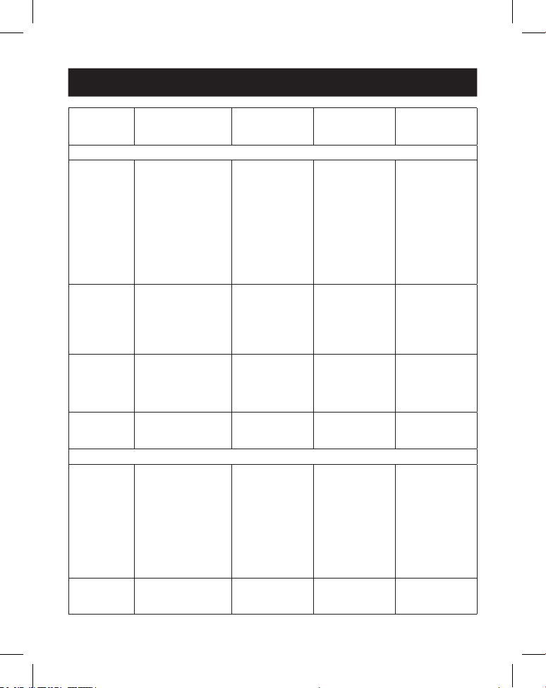
ASCII Command
Serial port protocol. Baud rate: 115200 (Default),
Data bits: 8, Stop bits: 1, Check bit: 0
x: Parameter 1, y: Parameter 2, !: Delimiter
Command
Code
Function
Description Example Feedback
Default
Setting
System Setting
help! List all commands help!
r status! Get device current
status
r status! get the unit all
status:
power, video
wall mode,
output
resolution
r type! Get device model r type! 1x4 video wall
controller
r fw version! Get rmware
version
r fw version! mcu fw version:
x.xx.xx

12
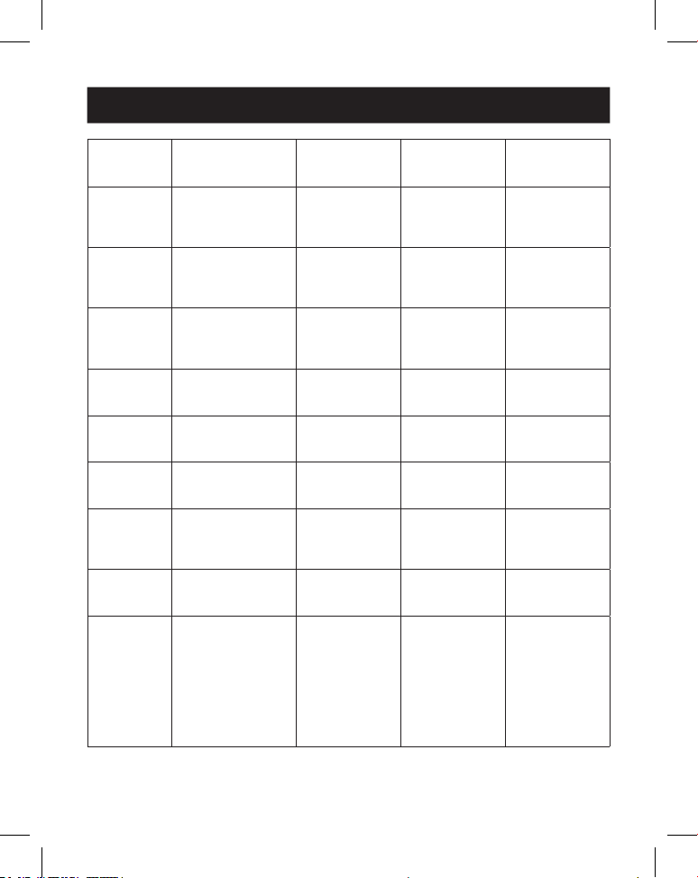
10. RS-232 Control Command
Command
Code
Function
Description Example Feedback
Default
Setting
s power z! Power on/o the
device, z=0~1
(z=0 power o, z=1
power on)
s power 1! power on
system
initializing...
initialization
nished!
mcu fw version:
x.xx.xx
r power! Get current power
state
r power! power on /
power o
s reboot! Reboot the device s reboot! reboot…
1x4 video wall
controller
system
initializing...
initialization
nished!
mcu fw version:
x.xx.xx
s reset! Reset to factory
defaults
1x4 video wall
controller
reset to factory
defaults
1x4 video wall
controller
system
initializing...
initialization
nished!
mcu fw version:
x.xx.xx
1. HDMI in;
2. EDID: 4K@60
4:4:4 2ch;
3. Audio mute
o;
4. 1x1 video wall
mode;
5. 1080p
output;
6. All HDMI out
no rotation;
7. H-Bezel=0,
V-Bezel=0;
13
10. RS-232 Control Command
Command
Code
Function
Description Example Feedback
Default
Setting
Input Setting
s input x
edid z!
Set input x edid
mode (x=0~2,
z=1~6)
x=0. all input x=1.
input1 x=2. input2
z=1. 4k60, 2.0ch
z=2. 4k60, 5.1ch
z=3. 4k30, 2.0ch
z=4. 4k30, 5.1ch
z=5. 1080p, 2.0ch
z=6. 1080p, 5.1ch
s input 1
edid 1!
input 1 edid:
4k60, 2.0ch
4k60,2.0ch
r input x
edid!
Get input x edid
mode (x=0~2)
x=0. all input x=1.
HDMI in
x=2. USB-C in
r input 1 edid! HDMI in edid:
4k60, 2.0ch
s output in
source x!
Route input source
to output ( x=1~2)
x=1. HDMI in
x=2. USB-C in
s output in
source 1!
output->HDMI
in
output->HDMI
in
r output in
source!
Get output y
selected input
source
r output in
source!
output->HDMI
in
Output Setting
s tw mode x! Set tv wall display
mode (x=1~8) x=1.
1x1 mode x=2.
2x1 mode x=3.
3x1 mode x=4.
4x1 mode x=5.
1x2 mode x=6. 1x3
mode x=7. 1x4
mode x=8. 2x2
mode
s tw mode 1! tv wall mode:
1x1
tv wall mode:
1x1
r tw mode! Get tv wall display
mode
r tw mode! tv wall mode:
2x2
s tw h bezel
+!
Set tv wall
horizontal bezel
s tw h bezel +! tv wall
horizontal
bezel: (bezel+1)
tv wall
horizontal
bezel: 0
14
10. RS-232 Control Command
Command
Code
Function
Description Example Feedback
Default
Setting
s tw h
bezel -!
Set tv wall
horizontal bezel
s tw h bezel -! tv wall
horizontal
bezel: (bezel-1)
tv wall
horizontal
bezel: 0
s tw h bezel
x!
Set tv wall
horizontal bezel
(x=0~10)
s tw h bezel 0! tv wall
horizontal
bezel: 0
tv wall
horizontal
bezel: 0
r tw h bezel! Get tv wall row
bezel
r tw h bezel! tv wall
horizontal
bezel: 0
s tw v bezel
+!
Set tv wall vertical
bezel
s tw v bezel +! tv wall vertical
bezel: (bezel+1)
tv wall vertical
bezel: 0
s tw v
bezel -!
Set tv wall vertical
bezel
s tw v bezel -! tv wall vertical
bezel: (bezel-1)
tv wall vertical
bezel: 0
s tw v bezel
x!
Set tv wall vertical
bezel (x=0~10)
s tw v bezel 0! tv wall vertical
bezel: 0
tv wall vertical
bezel: 0
r tw v bezel! Get tv wall vertical
bezel
r tw v bezel! tv wall vertical
bezel: 0
s tw res x! Set tv wall
resolution (x=1~4)
1.1280x720p60,
2. 1920x1080p60,
3. 3840x2160p30,
4. 1024x768@60
(XGA)
s tw res 2! tv wall
resolution:
1920x1080p60
tv wall
resolution:
1920x1080p60
r tw res! Get tv wall
resolution
r tw res! tv wall
resolution:
1920x1080p60
tv wall
resolution:
1920x1080p60
s output y
rotate x!
Set output y mirror
(y=1~4, x=0,1)
y=1. output 1
y=2. output 2
y=3. output 3
y=4. output 4
x=0. 0° rotation
x=1. 180° rotation
s output 1
rotate 0!
output1: 0°
rotation
output1:
0° rotation
output2:
0° rotation
output3:
0° rotation
output4: 0°
rotation
15
10. RS-232 Control Command
Command
Code
Function
Description Example Feedback
Default
Setting
r output y
rotation!
Get output y mirror
status (y=0~4) y=0.
output all y=1.
output 1
y=2. output 2
y=3. output 3
y=4. output 4
r output 0
rotation!
output1:
0° rotation
output2:
0° rotation
output3:
0° rotation
output4: 0°
rotation
s output
audio mute
x!
Set output audio
mute
on/o (x=0~1)
0. mute o
1. mute on
s output audio
mute 0!
output audio
mute: o
o
r output
audio mute!
Get output audio
mute
on/o
r output audio
mute!
output audio
mute: o

16
11. Application Example
Amplifier
Display 1
Display 2
Display 3
Display 4
Speakers
Laptop IR Receiver
Power
Supply
Media
Server or
Blu-ray
Player
Laptop
(with
USB-C
port)

17
12. Warranty
3-YEAR LIMITED WARRANTY
We warrant our products to be free from defects in materials and workmanship for a period of
three (3) years from the date of initial purchase. Our obligation under this warranty is limited to
repairing or replacing (at its sole option) any such defective products. Visit Tripplite.Eaton.com/
support/product-returns before sending any equipment back for repair. This warranty does not
apply to equipment which has been damaged by accident, negligence or misapplication or has
been altered or modied in any way.
EXCEPT AS PROVIDED HEREIN, WE MAKE NO WARRANTIES, EXPRESS OR IMPLIED, INCLUDING
WARRANTIES OF MERCHANTABILITY AND FITNESS FOR A PARTICULAR PURPOSE. Some states do
not permit limitation or exclusion of implied warranties; therefore, the aforesaid limitation(s) or
exclusion(s) may not apply to the purchaser.
EXCEPT AS PROVIDED ABOVE, IN NO EVENT WILL WE BE LIABLE FOR DIRECT, INDIRECT, SPECIAL,
INCIDENTAL OR CONSEQUENTIAL DAMAGES ARISING OUT OF THE USE OF THIS PRODUCT, EVEN
IF ADVISED OF THE POSSIBILITY OF SUCH DAMAGE. Specically, we are not liable for any costs,
such as lost prots or revenue, loss of equipment, loss of use of equipment, loss of software, loss
of data, costs of substitutes, claims by third parties, or otherwise.
FCC Notice, Class B
This device complies with part 15 of the FCC Rules. Operation is subject to the following two
conditions: (1) This device may not cause harmful interference, and (2) this device must accept
any interference received, including interference that may cause undesired operation.
Note: This equipment has been tested and found to comply with the limits for a Class B digital
device, pursuant to part 15 of the FCC Rules. These limits are designed to provide reasonable
protection against harmful interference in a residential installation. This equipment generates,
uses and can radiate radio frequency energy and, if not installed and used in accordance with
the instructions, may cause harmful interference to radio communications. However, there is
no guarantee that interference will not occur in a particular installation. If this equipment does
cause harmful interference to radio or television reception, which can be determined by turning
the equipment o and on, the user is encouraged to try to correct the interference by one or
more of the following measures:
• Reorient or relocate the receiving antenna.
• Increase the separation between the equipment and receiver.
• Connect the equipment into an outlet on a circuit dierent from that to which the receiver is
connected.
• Consult the dealer or an experienced radio/TV technician for help.
Any changes or modications to this equipment not expressly approved by Eaton could void the
user’s authority to operate this equipment.
Eaton has a policy of continuous improvement. Specications are subject to change without
notice.


19
Manual de Usuario
English 1
Français 36
Deutsch 53
Italiano 70
Modelo:
B119-1X4-4K6-VW
Controlador de Videowall –
4K a 60 Hz, Entrada HDMI/
USB-C, 4 Salidas HDMI
El producto comprado puede ser
diferente al de la imagen.

20
Índice
1. Instrucciones de Seguridad 21
2. Introducción 21
3. Características del Producto 22
4. Contenido del Paquete 22
5. Especificaciones 23
6. Controles y Funciones de Operación 25
7. Control Remoto IR 27
8. Asignación de Pines del cable IR 28
9. Videowall 28
10. Comando de control RS-232 29
11. Ejemplo de aplicación 34
12. Garantía 35

21
1. Instrucciones de Seguridad
2. Introducción
Gracias por comprar el B119-1X4-4K6-VW. Para un rendimiento y seguridad
óptimos, lea estas instrucciones cuidadosamente antes de conectar, operar o
ajustar este producto. Conserve este manual para futuras referencias.
Se recomienda un dispositivo de protección contra
sobretensiones
Este producto contiene componentes eléctricos sensibles que pueden dañarse
por picos de tensión, sobretensiones y otras interrupciones eléctricas. Se
recomienda encarecidamente el uso de sistemas de protección contra
sobretensión para proteger y prolongar la vida útil de su equipo.
El Controlador de Videowall está diseñado para captar, convertir, dirigir y distribuir
todos los formatos de señal de video a un mural de pantallas o videowall.
Cuenta con entrada HDMI y USB-C con resolución de hasta 4K @ 60 Hz (4:4:4) y 4
salidas HDMI. Admite varios modos de videowall que se pueden configurar para la
salida de video. También se admiten las salidas de desincrustación de audio
óptico y de audio analógico L/R.
Puede gestionar el Controlador de Videowall utilizando los botones del panel
frontal, el control remoto IR incluido o los comandos RS-232.

22
3. Características del Producto
4. Contenido del Paquete
• Admite entradas HDMI y USB-C con resoluciones 4K a 60 Hz y color 4:4:4
• Admite 8 modos de empalme de las pantallas: 1x1, 2x1, 3x1, 4x1, 1x2, 1x3, 1x4,
2x2
• Cumple con el estándar HDCP [High Definition Copy Protocol] 2.2 y con DP 1.2a
• Admite un ancho de banda de video de hasta 18 Gbps
• Admite la salida de desincrustación de audio óptico y audio analógico L/R
• Admite la rotación de imagen de 180°, conveniente para la instalación en
techos
• Admite el ajuste del bisel para el borde del empalme
• Administración Avanzada de EDID
• Control mediante botones del panel frontal, control remoto IR o comandos
RS-232
• Instalación sencilla del tipo conectar y usar, sin necesidad de configuraciones o
software
• Controlador de Videowall 1x4
• Fuente de Alimentación Externa
• Clavija de Alimentación con Bloqueo de 12 V y 1 A (AS/NZS 3112 Australia, BS
1363 R.U., CEE 7/16 Schuko, NEMA 1-15P Norteamérica)
• Control Remoto IR
• Cable Receptor IR de 5 V, 1.5 m [5 pies]
• Conector Phoenix de 3 pines de 3.81 mm
• (4) Tornillos para Máquina KM 3x4
• (2) Orejas de Instalación
• Documentación para el Usuario
23
5. Especificaciones
Aspectos técnicos
Compatibilidad con HDMI HDMI 2.0b
Compatibilidad HDCP
[High Denition Copy
Protocol]
HDCP [High Denition Copy Protocol] 2.2
Ancho de Banda de
Video
18 Gbps
Resolución de Video Entrada: hasta 4K a 60 Hz 4:4:4
Salida: 720p a 60 Hz, 1080p a 60 Hz, 4K a 30 Hz,
1024x768p a 60 Hz
Espacio de Color RGB, YCbCr_4:4:4, YCbCr_4:2:2, YCbCr_4:2:0
Color Verdadero 08/10/12 bits
Nivel IR 5Vp-p
Frecuencia IR 38 kHz
Formatos de Audio ENTRADA/SALIDA HDMI: LPCM 2.0/5.1, Dolby Digital/
Plus/EX, DTS, DTS-EX, DTS-96/24
SALIDA L/R: PCM 2.0
SPDIF (óptico): Dolby Digital/Plus, DTS 5.1, PCM 2.0
Latencia de Audio Sin Latencia
Latencia de Video Sin Latencia
ESD IEC 61000-4-2:
±8kV (descarga de espacio de aire), ±4kV (descarga de
contacto)
Conexión
Puertos de Entrada 1 HDMI [Tipo A, hembra de 19 pines]
1 USB-C [Tipo C, hembra de 24 pines]
Puertos de Salida 4 HDMI [Tipo A, hembra de 19 pines]
1 Audio Óptico [S/PDIF]
1 Audio L/R [RCA]
Puertos de Control 1 × RS-232 [Conector Phoenix de 3 pines de 3.81 mm]
1 IR EXT [3.5 mm, Mini-Jack Estéreo]
24
5. Especificaciones
Mecánicas
Gabinete Metal
Color Negro
Dimensiones
((Al x An x Pr), (Alto x
Ancho x Profundidad))
30 x 220 x 100 mm [1.2 x 8.7 x 3.9"]
Peso 590 g [1.3 lb]
Fuente de Alimentación Entrada: CA 100–240 V, 50/60 Hz
Salida: CD 12 V 1 A
(Certicado por la norma de EE. UU./UE, CE/FCC/UL)
Consumo de Energía 5.5 W (máx)
Temperatura de
Operación
32 ° (104 °F ), 0 ° (40 °C)
Temperatura de
Almacenamiento
-4 ° (140 °F ), -20 ° (60 °C)
Humedad Relativa De 20 % a 90 % de HR (Sin Condensación)
Resolución de Video 4K a 60 Hz 4K a 24 Hz 1080p a 60 Hz
Longitud de Cable HDMI
(Entrada/Salida HDMI)
8 m [26 pies] 10 m [32 pies] 15 m [49 pies]
Se recomienda encarecidamente el uso del cable "HDMI de alta velocidad
Premium".

25
6. Controles y Funciones de Operación
6.1 Panel Frontal
1
1
2
2
4
4
6
6
7
7
9
9
8
8
J
J
3
3
5
5
1
Botón “Power” [Encendido]: Presiónelo para encender la unidad en estatus
apagado/en espera. En estatus encendido, presione durante 2 a 3 segundos
para ingresar el estatus modo de espera.
2
LED de Encendido: Se ilumina en verde durante el funcionamiento normal.
Se ilumina en rojo durante el estatus modo de espera.
3
LED HDMI: Se ilumina en verde cuando se selecciona la entrada HDMI.
4
LED USB-C: Se ilumina en verde cuando se selecciona la entrada USB-C.
5
LED Auto: Se ilumina en verde cuando la función de conmutación automática
está habilitada.
6
Ventana IR: Ventana de recepción de señal IR.
7
Botón HDMI: Presione para seleccionar el canal de entrada HDMI.
8
Botón USB-C: Presione para seleccionar el canal de entrada USB-C.
9
Botón de modo: Presione para elegir uno de los 8 modos de empalme.
J
Botón RES: Presione para elegir una de las 4 resoluciones de salida HDMI.

26
6. Controles y Funciones de Operación
6.2 Panel Posterior
1
1
2
2
3
3
4
4
5
5
7
7
6
6
8
8
1
Entrada HDMI: El puerto de entrada de señal HDMI se conecta a un
dispositivo fuente HDMI.
2
Entrada USB-C: El puerto de entrada de señal USB-C se conecta a un
dispositivo fuente USB-C.
3
Salida de Audio Óptico: Se conecta a un dispositivo de salida de audio
óptico, como un amplificador de audio.
4
Salida de Audio L/R: Se conecta a un dispositivo de salida de audio
analógico, como una bocina.
5
Salida Videowall (HDMI 1-4): Los puertos de salida de señal HDMI se
conectan a pantallas HDMI.
6
Conector Phoenix de 3 Pines RS-232: Se conecta a una PC o un sistema de
control para la actualización del puerto serial o el control de comandos
RS-232.
7
IR EXT: El puerto de recepción de señal IR se conecta al cable de receptor IR
incluido. Si la ventana derecepción de la señal de infrarrojos (vea 6.1 Panel
Frontal) está bloqueada o la unidad está instalada en un área cerrada fuera
de la línea de visión de infrarrojos, el cable receptor de infrarrojos puede
conectarse a este puerto para recibir la señal remota de infrarrojos.
8
CD12 V: Se conecta a la fuente de alimentación externa incluida.
27
7. Control Remoto IR
1
Encendido o Modo en espera:
Presione para encender el
dispositivo o para ponerlo en
modo en espera.
2
Silencio: Presione para apagar o
encender la salida de audio, lo
que incluye HDMI, audio óptico y
audio L/R.
3
HDMI: Presione para seleccionar
el canal de entrada HDMI.
4
USB-C: Presione para seleccionar
el canal de entrada USB-C.
5
AUTO: Presione para desactivar
o activar la conmutación
automática de entrada.
6
Rotación 1/2/3/4: Presione para
conmutar el ángulo de rotación
entre 0˚ y 180˚ para el canal de
salida correspondiente.
7
Resolución 720P/1080P/4K/
XGA: Presione para conmutar la
resolución de los 4 canales de
salida al mismo tiempo.
8
MODO VIDEOWALL: Hay 8
modos de empalme: 1x1, 2x1,
3x1, 4x1, 1x2, 1x3, 1x4, 2x2.
Presione para seleccionar el
modo de visualización.
9
H/V-BEZEL: Presione para ajustar
los biseles de las imágenes que
empalman.
1
1
3
3
4
4
6
6
7
7
8
8
9
9
2
2
5
5

28
8. Asignación de Pines del Cable IR
9. Videowall
RECEPTOR IR RECEPTOR IR
1
Señal IR
2
Alimentación
3
Conexión a
Tierra
El sistema videowall admite los siguientes ocho modos de empalme:
Puede configurar los modos de visualización con los botones del panel frontal, el
control remoto por infrarrojos o los comandos RS-232.
Nota: En el modo videowall (excepto 1x1), solo las pantallas que se seleccionan para realizar el
empalme videowall mostrarán imágenes, y su bisel se puede ajustar.
29
10. Comando de Control RS-232
1
Señal IR
2
Alimentación
3
Conexión a
Tierra
El Controlador de Videowall admite el control de comandos RS-232. Conecte su
puerto RS-232 a una PC con un cable conector Phoenix de 3 pines y un cable
RS-232 a USB. El método de conexión es el siguiente:
Luego, abra una herramienta de Comando Serial en la PC para enviar el comando
ASCII y controlar el dispositivo. La lista de comandos ASCII se muestra a
continuación.
Comando ASCII
Protocolo de puerto serial. Velocidad de transmisión: 115200 (Predeterminado),
Bits de datos: 8, Bits de parada: 1, Bit de vericación: 0
x: Parámetro 1, y: Parámetro 2, !: Delimitador
Código de
Comando
Descripción de la
Función Ejemplo
Retro-
alimentación
Parámetro
Predetermi-
nado
Parámetro del Sistema
help! Listar todos los
comandos
help!
r status! Obtener estatus
actual del dispositivo
r status! Obtenga el
estatus completo
de la unidad:
potencia, modo
de videowall,
resolución de
salida
r type! Obtener el modelo
del dispositivo
r type! Controlador de
videowall 1x4
r fw version! Obtener la versión
del rmware
r fw version! versión del fw del
mcu x.xx.xx

30
10. Comando de Control RS-232
Código de
Comando
Descripción de la
Función Ejemplo
Retro-
alimentación
Parámetro
Predetermi-
nado
s power z! Encienda/apague el
dispositivo, z=0~1
(z=0 apagado, z=1
encendido)
s power 1! inicializando
encendido del
sistema... ¡la
inicialización ha
terminado!
versión del fw del
mcu x.xx.xx
r power! Obtener el estatus
de energía actual
r power! encender/apagar
s reboot! Reiniciar el
dispositivo
s reboot! reiniciar...
Inicializando
sistema de
control de
videowall 1x4...
¡la inicialización
ha terminado!
versión del fw del
mcu x.xx.xx
s reset! Restaurar a
los valores
predeterminados de
fábrica
Controlador de
videowall 1x4
Restaurar a los
valores prede-
terminados de
fábrica
Inicializando
sistema de
control de
videowall 1x4...
¡la inicialización
ha terminado!
versión del fw del
mcu x.xx.xx
1. Entrada HDMI;
2. EDID: 4K a 60
4:4:4 2 canales;
3. Audio
silenciado
apagado
4. Modo de
videowall 1x1;
5. Salida de
1080p;
6. Todas las
salidas HDMI sin
rotación;
7. Bisel en H=0,
Bisel en V=0;
31
10. Comando de Control RS-232
Código de
Comando
Descripción de la
Función Ejemplo
Retro-
alimentación
Parámetro
Predetermi-
nado
Parámetro de Entrada
s input x
edid z!
Congure la entrada
en modo edid
(x=0~2, z=1~6)
x=0. all input x=1.
input1 x=2. input2
z=1. 4k60, 2.0ch z=2.
4k60, 5.1ch z=3.
4k30, 2.0ch z=4.
4k30, 5.1ch z=5.
1080p, 2.0ch
z = 6. 1080p, 5.1ch
s entrada 1
edid 1!
entrada 1: edid:
4k60, 2.0ch
4k60, 2.0ch
r input x edid! Obtenga la entrada
en modo edid
(x=0~2)
x=0. all input x=1.
Entrada HDMI
x=2. USB-C en
r input 1 edid! HDMI en edid:
4k60, 2.0ch
s output in
source x!
Envíe la fuente de
entrada a la salida
(x=1~2)
x=1. Entrada HDMI
x=2. Entrada USB-C
s output in
source 1!
salida -> entrada
HDMI
salida -> entrada
HDMI
r output in
source!
Obtener la salida y
la fuente de entrada
seleccionada.
r output in
source!
salida -> entrada
HDMI
Parámetro de Salida
s tw mode x! Congure el modo
de visualización de
las pantallas en muro
(x=1~8) x=1. Modo
1x1 x=2. Modo 2x1
x=3. Modo 3x1 x=4.
Modo 4x1 x=5. Modo
1x2 x=6. Modo 1x3
x=7. Modo 1x4 x=8.
Modo 2x2
s tw mode 1! Modo pantallas
en muro: 1x1
Modo pantallas
en muro: 1x1
r tw mode! Obtener el modo
de visualización de
muro de video
r tw mode! Modo pantallas
en muro: 2x2
32
10. Comando de Control RS-232
Código de
Comando
Descripción de la
Función Ejemplo
Retro-
alimentación
Parámetro
Predetermi-
nado
s tw h bezel
+!
Congure el bisel
horizontal de las
pantallas en muro.
s tw h bezel +! Bisel horizontal
de las pantallas
en muro:
(bisel+1).
Bisel horizontal
de las pantallas
en muro: 0
s tw h bezel -! Congure el bisel
horizontal de las
pantallas en muro.
s tw h bezel -! Bisel horizontal
de las pantallas
en muro:
(bisel-1).
Bisel horizontal
de las pantallas
en muro: 0
s tw h bisel x! Establecer el bisel
horizontal de las
pantallas en muro
(x=0~10,+,-).
s tw h bezel 0! Bisel horizontal
del muro de
video: 0
Bisel horizontal
del muro de
video: 0
r tw h bezel! Obtener el bisel del
muro de video
r tw h bezel! Bisel horizontal
de las pantallas
en muro: 0
s tw v bezel +! Congure el bisel
vertical de las
pantallas en muro.
s tw v bezel +! Bisel vertical de
las pantallas en
muro: (bisel + 1).
Bisel vertical de
las pantallas en
muro: 0
s tw v bezel -! Congure el bisel
vertical de las
pantallas en muro.
s tw v bezel -! Bisel vertical de
las pantallas en
muro: (bisel-1).
Bisel vertical de
las pantallas en
muro: 0
s tw v bezel x! Establecer el bisel
vertical de las
pantallas en muro
(x=0~10).
s tw v bezel 0! Bisel vertical del
muro de video: 0
Bisel vertical del
muro de video: 0
r tw v bezel! Obtener un bisel
vertical para muro
de video
r tw v bezel! Bisel vertical de
las pantallas en
muro: 0
s tw res x! Congure la
resolución de las
pantallas en muro
(x=1~4).
1.1280x720p60,
2. 1920x1080p60,
3. 3840x2160p30,
4. 1024x768 a 60
(XGA)
s tw res 2! resolución
de pantallas
en muro:
1920x1080p60
resolución
de pantallas
en muro:
1920x1080p60

33
10. Comando de Control RS-232
Código de
Comando
Descripción de la
Función Ejemplo
Retro-
alimentación
Parámetro
Predetermi-
nado
r tw res! Obtener la
resolución del muro
de video
r tw res! resolución
de pantallas
en muro:
1920x1080p60
resolución
de pantallas
en muro:
1920x1080p60
s output y
rotate x!
Congure la salida
y el espejo (y=1~4,
x=0,1).
y=1. output 1
y=2. output 2
y=3. output 3
y=4. output 4
x=0. Rotación de 0°
x=1. Rotación de
180°
s output 1
rotate 0!
output1: 0° de
rotación
output1: 0° de
rotación output2:
0° de rotación
output3: 0° de
rotación output4:
0° de rotación
r output y
rotation!
Obtener el estatus
de salida y espejo
(y=0~4) y=0. output
all y=1. output 1
y=2. output 2
y=3. output 3
y=4. output 4
r output 0
rotation!
output1: 0° de
rotación output2:
0° de rotación
output3: 0° de
rotación output4:
0° de rotación
s output
audio mute x!
Congure el audio
de salida en modo
silencio
activado/desactivado
(x=0~1)
0. silencio
desactivado
1. silencio activado
s output audio
mute 0!
salida de audio
silencio:
desactivado
desactivado
r output
audio mute!
Silencie la salida de
audio
activado/desactivado
r output audio
mute!
salida de audio
silencio:
desactivado

34
11. Ejemplo de Solicitud
Amplificador
Pantalla 1
Pantalla 2
Pantalla 3
Pantalla 4
Bocinas
Laptop Receptor IR
Fuente de
Alimentación
Servidor
multimedia
o
reproductor
de Blu-ray
Laptop
(con
puerto
USB-C)

35
12. Garantía
GARANTÍA LIMITADA DE 3 AÑOS
Garantizamos por tres (3) años a partir de la fecha de compra inicial que nuestros productos no
presentan defectos de materiales ni de mano de obra. Nuestra obligación bajo esta garantía está
limitada a la reparación o reemplazo (a su entera discreción) de cualquier producto defectuoso.
Visite Tripplite.Eaton.com/support/product-returns antes de enviar cualquier equipo para su
reparación. Esta garantía no se aplica a equipos que hayan sido dañados por accidente, negli-
gencia o mal uso o hayan sido alterados o modicados de alguna manera.
SALVO POR LO QUE SE INDICÓ AQUÍ, NO OTORGAMOS GARANTÍAS EXPRESAS O IMPLÍCITAS, IN-
CLUIDAS GARANTÍAS DE COMERCIABILIDAD Y ADECUACIÓN PARA UN PROPÓSITO PARTICULAR.
Algunos estados no permiten la limitación o exclusión de garantías implícitas; por lo tanto, las
limitaciones o exclusiones antes mencionadas pueden no aplicarse al comprador.
SALVO POR LO QUE SE INDICÓ ANTERIORMENTE, EN NINGÚN CASO SEREMOS RESPONSABLES
POR DAÑOS DIRECTOS, INDIRECTOS, ESPECIALES, INCIDENTALES O CONSECUENTES QUE
SURJAN DEL USO DE ESTE PRODUCTO, INCLUSO SI SE ADVIERTE SOBRE LA POSIBILIDAD DE TAL
DAÑO. Especícamente, no somos responsables por ningún costo, como pérdida de ganancias
o ingresos, pérdida de equipos, pérdida del uso de equipos, pérdida de software, pérdida de
datos, costos de sustituciones, reclamos de terceros o de cualquier otra forma.
Eaton tiene una política de mejora continua. Las especicaciones están sujetas a cambio sin
previo aviso.
Eaton
1000 Eaton Boulevard
Cleveland, OH 44122
Estados Unidos
Eaton.com
© 2025 Eaton
Todos los Derechos
Reservados
Publicación N.° 25-03-221 /
93-4AF9_RevA
Abril de 2025
Eaton es una marca
registrada.
Todas las marcas registradas
son propiedad de sus
respectivos dueños.
36
Manuel d'utilisation
English 1
Españo19
Deutsch53
Italiano70
Modèle:
B119-1X4-4K6-VW
Contrôleur de mur vidéo–4K
60Hz, entrée HDMI/USB-C,
4sorties HDMI
Le produit acheté peut différer de l'image.

37
Sommaire
1. Consignes de sécurité 38
2. Introduction 38
3. Caractéristiques du produit 39
4. Contenu de l'emballage 39
5. Caractéristiques techniques 40
6. Contrôles et fonctions d'utilisation 42
7. Télécommande IR 44
8. Affectation de la broche du câble IR 45
9. Mur vidéo 45
10. Commande de contrôle RS-232 46
11. Exemple d'application 51
12. Garantie 52

38
1. Consignes de sécurité
2. Introduction
Nous vous remercions d'avoir acheté le B119-1X4-4K6-VW. Pour des
performances et une sécurité optimales, veuillez lire attentivement ces
instructions avant de connecter, d'utiliser ou de régler ce produit. Veuillez
conserver ce manuel pour référence ultérieure.
Dispositif de protection contre les surtensions recommandé
Ce produit contient des composants électriques sensibles qui peuvent être
endommagés par des pointes électriques, des surtensions et d'autres coupures
de courant. L'utilisation de systèmes de protection contre les surtensions est
fortement recommandée afin de protéger et de prolonger la durée de vie de votre
équipement.
Le contrôleur de mur vidéo est conçu pour capturer, convertir, acheminer et
distribuer tous les formats de signaux vidéo vers un mur vidéo.
Il dispose d'une entrée HDMI et USB-C avec une résolution pouvant atteindre 4K
@ 60Hz (4:4:4) et 4sorties HDMI. Il prend en charge de multiples modes de mur
vidéo à définir pour la sortie vidéo. De plus, la sortie de désembeddage audio
optique et audio analogique L/R est également prise en charge.
Vous pouvez commander le contrôleur de mur vidéo à l'aide des boutons du
panneau avant, de la télécommande infrarouge fournie ou des commandes
RS-232.

39
3.Caractéristiques du produit
4. Contenu de l'emballage
• Prend en charge les entrées HDMI et USB-C avec des résolutions 4K @ 60Hz
et couleur 4:4:4
• Prend en charge 8modes d'épissure de mur vidéo : 1x1, 2x1, 3x1, 4x1, 1x2,
1x3, 1x4, 2x2
• Conforme aux normes HDCP 2.2 et DP 1.2a
• Prend en charge une bande passante vidéo allant jusqu'à 18Gbit/s
• Prend en charge la sortie optique audio et le désembeddage audio analogique
L/R
• Prend en charge la rotation de l'image à 180°, pratique pour l'installation au
plafond
• Prend en charge l'ajustement du cadre pour le bord d'épissure
• Gestion des EDID avancée
• Contrôle à l'aide des boutons du panneau avant, de la télécommande
infrarouge ou des commandes RS-232
• Installation plug-and-play simple, sans configuration ni logiciels nécessaires
• 1x4 contrôleur de mur vidéo
• Alimentation électrique externe
• Fiche d'alimentation verrouillable 12V 1A (AS/NZS 3112 Australie, BS 1363 R.-U.,
CEE 7/16 Schuko, NEMA 1-15P Amérique du Nord)
• Télécommande IR
• Câble récepteur IR 5V, 1,5m (5pi.)
• Connecteur Phoenix 3,81mm à 3broches
• (4) vis mécaniques KM 3x4
• (2) oreilles de montage
• Documentation pour l’utilisateur

40
5. Caractéristiques techniques
Technique
Conformité HDMI HDMI 2.0b
Conformité HDCP HDCP 2.2
Largeur de bande vidéo 18Gbit/s
Résolution vidéo Entrée: jusqu'à 4K @ 60Hz 4:4:4
720p @ 60Hz, 1080p @ 60Hz, 4K @ 30Hz,
1024x768p @ 60Hz
Espace colorimétrique RGB, YCbCr_4:4:4, YCbCr_4:2:2, YCbCr_4:2:0
Profondeur de couleur 8/10/12bits
Niveau IR 5Vp-p
Fréquence IR 38kHz
Formats audio ENTRÉE/SORTIE HDMI: LPCM 2.0/5.1, Dolby Digital/
Plus/EX, DTS, DTS-EX, DTS-96/24
SORTIE L/R: PCM 2.0
SPDIF (optique): Dolby Digital/Plus, DTS 5.1, PCM 2.0
Latence audio Aucune latence
Latence vidéo Aucune latence
ESD CEI 61000-4-2:
±8kV (décharge d'entrefer), ±4kV (décharge de
contact)
Connexion
Ports d'entrée 1 × HDMI [type A, prise femelle à 19broches]
1 × USB-C [Type C, prise femelle à 24broches]
Ports de sortie 4 × HDMI [type A, prise femelle à 19broches]
1 × Audio optique [S/PDIF]
1 × Audio L/R [RCA]
Ports de contrôle 1 × RS-232 [connecteur Phoenix à 3 broches de
3,81mm]
1 × Prolongateur IR [3,5mm, mini-jack stéréo]
41
5. Caractéristiques techniques
Mécanique
Boîtier Métal
Couleur Noir
Dimensions (H x L x P) 30 x 220 x 100mm (1,2 x 8,7 x 3,9po)
Poids 590g (1,3lb.)
Bloc d'alimentation Entrée: 100–240VCA, 50/60Hz
Sortie: 12VCC 1A
(Norme US/UE, certié CE/FCC/UL)
Consommation élec-
trique
55W (max.)
Température de fonc-
tionnement
0 - 40°C (32 - 104°F)
Température de stockage -20 - 60°C (-4 - 140°F)
Humidité relative 20% - 90% HR (sans condensation)
Résolution vidéo 4K @ 60Hz 4K @ 24Hz 1080p 60 Hz
Longueur du câble HDMI
(Entrée/sortie HDMI)
8m (26pi.) 10m (32pi.) 15m (49pi.)
L'utilisation d'un câble HDMI haute vitesse et haut de gamme est fortement
recommandée.

42
6. Contrôles et fonctions d'utilisation
6.1 Panneau avant
1
1
2
2
4
4
6
6
7
7
9
9
8
8
J
J
3
3
5
5
1
Bouton d'alimentation: appuyez dessus pour éteindre/mettre en veille
l'appareil. Lorsque l'appareil est sous tension, appuyez pendant 2 à
3secondes pour le mettre en veille.
2
LED d'alimentation: s'allume en vert pendant le fonctionnement normal.
Les voyants s'allument en rouge lorsque l'appareil est en veille.
3
LED HDMI: s'allume en vert lorsque l'entrée HDMI est sélectionnée.
4
LED USB-C: s'allume en vert lorsque l'entrée USB-C est sélectionnée.
5
LED automatique: s'allume en vert lorsque la fonction de commutation
automatique est activée.
6
Fenêtre IR: fenêtre de réception du signal IR.v
7
Bouton HDMI: appuyez pour sélectionner le canal d'entrée HDMI.
8
Bouton USB-C: appuyez pour sélectionner le canal d'entrée USB-C.
9
Bouton Mode: appuyez pour choisir l'un des 8modes d'épissure.
J
Bouton RES: appuyez sur ce bouton pour choisir l'une des 4résolutions de
sortie HDMI.

43
6. Contrôles et fonctions d'utilisation
6.2 Panneau arrière
1
1
2
2
3
3
4
4
5
5
7
7
6
6
8
8
1
Entrée HDMI: le port d'entrée de signal HDMI se connecte à un appareil
source HDMI.
2
Entrée USB-C: le port d'entrée de signal USB-C se connecte à un appareil
source USB-C.
3
Sortie audio optique: se connecte à un dispositif de sortie audio optique,
tel qu'un amplificateur audio.
4
Sortie audio L/R: se connecte à un dispositif de sortie audio analogique, tel
qu'un haut-parleur.
5
Sortie du mur vidéo (HDMI 1–4): les ports de sortie de signal HDMI se
connectent aux écrans HDMI.
6
Connecteur Phoenix à 3broches RS-232: se connecte à un PC ou à un
système de contrôle pour la mise à niveau du port série ou le contrôle par
commande RS-232.
7
Prolongateur IR: le port de réception du signal IR se connecte au câble
récepteur IR inclus. Si la fenêtre de réception du signal IR (voir 6.1 Panneau
avant) est bloquée ou si l'appareil est installé dans un espace fermé hors de
la ligne de visée infrarouge, le câble du récepteur IR peut être connecté à ce
port pour recevoir le signal de la télécommande IR.
8
12VCC: se connecte à l'alimentation externe fournie.

44
7. Télécommande IR
1
Mise sous tension ou en
veille: appuyez sur ce bouton
pour allumer l'appareil ou le
mettre en mode VEILLE.
2
Mode muet: appuyez sur ce
bouton pour désactiver ou activer
la sortie audio, y compris l'audio
HDMI, optique et L/R.
3
HDMI: appuyez sur ce bouton
pour sélectionner le canal
d'entrée HDMI.
4
USB-C: appuyez sur ce bouton
pour sélectionner le canal
d'entrée USB-C.
5
AUTO: appuyez sur ce bouton
pour désactiver ou activer la
commutation automatique de
l'entrée.
6
Rotation 1/2/3/4: appuyez sur
ce bouton pour commuter l'angle
de rotation entre 0˚ et 180˚ pour
le canal de sortie correspondant.
7
Résolution 720P/1080P/4K/
XGA: appuyez sur ce bouton
pour commuter la résolution des
4canaux de sortie en même
temps.
8
MODE MUR VIDÉO: il existe
8modes d'épissure: 1x1, 2x1,
3x1, 4x1, 1x2, 1x3, 1x4, 2x2.
Appuyez pour sélectionner le
mode d'affichage.
9
H/V-BEZEL: appuyez sur ce
bouton pour ajuster les cadres
des images d'épissure.
1
1
3
3
4
4
6
6
7
7
8
8
9
9
2
2
5
5
RÉCEPTEUR IR

45
8. Affectation de la broche du câble IR
9. Mur vidéo
RÉCEPTEUR IR RÉCEPTEUR IR
1
Signal IR
2
Alimentation
3
Mise à la terre
Le mur vidéo prend en charge huit modes d'épissage comme suit:
Vous pouvez régler les modes d'affichage via les boutons du panneau avant, la
télécommande infrarouge ou les commandes RS-232.
Remarque: en mode mur vidéo (sauf 1x1), seuls les écrans sélectionnés pour effectuer l'épissure du
mur vidéo peuvent afficher des images, et leur cadre peut être ajusté.

46
10. Commande de contrôle RS-232
Le contrôleur du mur vidéo prend en charge le contrôle par commande RS-232.
Connectez son port RS-232 à un PC avec un câble de connexion Phoenix à
3broches et un câble RS-232 vers USB. La méthode de connexion est la suivante:
Ensuite, ouvrez un outil de commande série sur PC pour envoyer une commande
ASCII pour contrôler l'appareil. La liste de commandes ASCII est indiquée
ci-dessous.
Commande ASCII
Protocole du port série. Baud Rate (Vitesse de transmission): 115200 (par défaut),
Bits de données: 8, Bits d'arrêt: 1, Bit de contrôle: 0
x: Paramètre 1, y: Paramètre 2,!: Délimiteur
Code de
commande
Description
fonctionnelle Exemple
Retour
d'information
Réglage
par défaut
Réglage du système
help! Lister toutes les
commandes
help!
r status! Obtenir l'état actuel
de l'appareil
r status! obtenir l'état
complet de
l'unité:
puissance, mode
mur vidéo,
résolution de
sortie
r type! Obtenir le modèle de
l'appareil
r type! Contrôleur de
mur vidéo 1x4
47
10. Commande de contrôle RS-232
Code de
commande
Description
fonctionnelle Exemple
Retour
d'information
Réglage
par défaut
r fw version! Obtenir la version du
rmware
r fw version! Version du
rmware du
microcontrôleur:
x.xx.xx
s power z! Allumer/éteindre
l'appareil, z = 0~1
(z = 0 mise hors
tension, z = 1 mise
sous tension)
s power 1! Mise sous ten-
sion, initialisation
du système...
initialisation
terminée!
Version du
rmware du
microcontrôleur:
x.xx.xx
r power! Obtenir l'état actuel
de l'alimentation
r power! mise sous
tension/hors
tension
s reboot! Redémarrer
l'appareil
s reboot! redémarrage en
cours...
Système de
contrôle de mur
vidéo 1x4 en
cours d'initialisa-
tion... initialisation
terminée!
Version du
rmware du
microcontrôleur:
x.xx.xx
s reset! Réinitialiser les
paramètres d'usine
Contrôleur de
mur vidéo 1x4
Réinitialiser les
paramètres
d'usine
Système de
contrôle de mur
vidéo 1x4 en
cours d'initialisa-
tion... initialisation
terminée!
Version du
rmware du
microcontrôleur:
x.xx.xx
1. Entrée HDMI;
2. EDID: 4K@60
4:4:4 2canaux;
3. Désactivez le
son audio;
4. Mode d'écran
vidéo 1x1;
5. Sortie 1080p;
6. Toutes les
sorties HDMI
sans rotation;
7. H-Bezel = 0,
V-Bezel = 0;

48
10. Commande de contrôle RS-232
Code de
commande
Description
fonctionnelle Exemple
Retour
d'information
Réglage
par défaut
Réglage d'entrée
s input x
edid z!
Dénir le mode
d'entrée x edid
(x = 0~2, z = 1~6)
x = 0. toutes les
entrées x = 1.
entrée1 x = 2.
entrée2
z = 1. 4k60,
2,00canaux z = 2.
4k60, 5,1 canaux z =
3. 4k30, 2,0canaux z
= 4. 4k30, 5,1canaux
z = 5. 1080p,
2,0canaux
z = 6. 1080p,
5,1canaux
entrée s 1
edid 1!
entrée 1 edid:
4k60, 2,0canaux
4k60, 2,0canaux
r input x edid! Obtenir le mode
entrée x edid
(x = 0~2)
x = 0. toutes les
entrées x = 1.
Entrée HDMI
x = 2. Entrée USB-C
r input 1 edid! HDMI dans
l'EDID: 4k60, 2,0
canaux
s output in
source x!
Diriger la source
d'entrée vers la sortie
(x = 1~2)
x = 1. Entrée HDMI
x = 2. Entrée USB-C
s output in
source 1!
sortie -> entrée
HDMI
sortie -> entrée
HDMI
r output in
source!
Obtenir la sortie y
sélectionnée dans la
source d'entrée
r output in
source!
sortie -> entrée
HDMI
49
10. Commande de contrôle RS-232
Code de
commande
Description
fonctionnelle Exemple
Retour
d'information
Réglage
par défaut
Réglage de la sortie
s tw mode x! dénir le mode
d'achage du mur tv
(x = 1~8) x = 1. Mode
1x1 x = 2. Mode 2x1
x = 3. Mode 3x1 x
= 4. Mode 4x1 x =
5. Mode 1x2 x = 6.
Mode 1x3 x = 7.
Mode 1x4 x = 8.
Mode 2x2
s tw mode 1! Mode du mur
TV: 1x1
Mode du mur
TV: 1x1
r tw mode! Obtenir le mode
d'achage du
mur TV
r tw mode! Mode d'achage
du mur tb: 2x2
s tw h bezel +! Installer le cadre
horizontal du mur tv
s tw h bezel +! cadre horizontal
du mur tv: (cadre
+ 1)
cadre horizontal
du mur tv: 0
s tw h bezel -! Installer le cadre
horizontal du mur tv
s tw h bezel -! cadre horizontal
du mur tv: (cadre
- 1)
cadre horizontal
du mur tv: 0
s tw h bezel x! Régler le cadre
horizontal du mur tv
(x = 0~10)
s tw h bezel 0! Cadre horizontal
du mur TV: 0
Cadre horizontal
du mur TV: 0
r tw h bezel! Obtenir le cadre de
rangée du mur TV
r tw h bezel! cadre horizontal
du mur tv: 0
s tw v bezel +! Installer le cadre
vertical du mur tv
s tw v bezel +! cadre vertical du
mur tv: (cadre
+ 1)
cadre vertical du
mur tv: 0
s tw v bezel -! Installer le cadre
vertical du mur tv
s tw v bezel -! cadre vertical du
mur tv: (cadre
- 1)
cadre vertical du
mur tv: 0
s tw v bezel x! Régler le cadre
vertical du mur tv (x
= 0~10)
s tw v bezel 0! Cadre vertical du
mur TV: 0
Cadre vertical du
mur TV: 0
r tw v bezel! Obtenir le cadre
vertical du mur TV
r tw v bezel! cadre vertical du
mur tv: 0
50
10. Commande de contrôle RS-232
Code de
commande
Description
fonctionnelle Exemple
Retour
d'information
Réglage
par défaut
s tw res x! Dénir la résolution
du mur TV (x = 1~4)
1. 1280x720p60,
2. 1920x1080p60,
3. 3840x2160p30,
4. 1024x768@60
(XGA)
s tw res 2! résolution
du mur tv:
1920x1080p60
résolution
du mur tv:
1920x1080p60
r tw res! Obtenir la résolution
du mur TV
r tw res! résolution
du mur tv:
1920x1080p60
résolution
du mur tv:
1920x1080p60
s output y
rotate x!
Dénir la sortie y
miroir (y = 1~4, x
= 0,1)
y = 1. sortie 1
y = 2. sortie 2
y = 3. sortie 3
y = 4. sortie 4
x = 0. Rotation de 0°
x = 1. Rotation de
180°
sortie s 1
rotate 0!
sortie: rotation
de 0°
sortie1: rotation
de 0° sortie2:
rotation de 0°
sortie3: rotation
de 0° sortie4:
rotation de 0°
r output y
rotation!
Obtenir l'état de
sortie du miroir y
(y = 0~4) y = 0. toutes
les sorties y = 1.
sortie 1
y = 2. sortie 2
y = 3. sortie 3
y = 4. sortie4
r output 0
rotation!
sortie1: rotation
de 0° sortie2:
rotation de 0°
sortie3: rotation
de 0° sortie4:
rotation de 0°
s output
audio mute x!
Dénir la sortie audio
en mode muet
sous tension/hors
tension (x = 0~1)
0. Mode muet
désactivé
1. Mode muet activé
s output audio
mute 0!
sortie audio
Mode muet:
désactivé
désactivé
r output
audio mute!
Obtenir la sortie
audio muette
activé/désactivé
r output audio
mute!
sortie audio
Mode muet:
désactivé

51
11. Exemple d'application
Amplificateur
Affichage1
Affichage2
Affichage3
Affichage4
Haut-parleurs
Ordinateur
portable
Récepteur IR
Bloc
d'alimentation
Serveur
multimé-
dia ou
lecteur
Blu-ray
Ordinateur
portable
(avec port
USB-C)

52
12. Garantie
GARANTIE LIMITÉE DE 3ANS
Nous garantissons que nos produits sont exempts de défauts de matériaux et de fabrication
pendant une période de trois (3) ans à compter de la date d'achat initiale. Notre obligation au ti-
tre de cette garantie est limitée à la réparation ou au remplacement (à notre seule discrétion) de
tout produit défectueux. Rendez-vous sur Tripplite.Eaton.com/support/product-returns avant de
renvoyer tout équipement pour réparation. Cette garantie ne s'applique pas aux équipements
qui ont été endommagés par accident, négligence ou par une mauvaise utilisation, ni à ceux qui
ont été altérés ou modiés d'une façon quelconque.
SAUF MENTION CONTRAIRE DANS LE PRÉSENT DOCUMENT, NOUS NE FOURNISSONS AUCUNE
GARANTIE, EXPLICITE OU IMPLICITE, Y COMPRIS LES GARANTIES DE QUALITÉ MARCHANDE ET
DE VOCATION À UN BUT PARTICULIER. Certains États ne permettent ni la limitation ni l'exclusion
de garanties implicites; ainsi, la/les limitation(s) ou exclusion(s) mentionnée(s) ci-dessus peut/
peuvent ne pas s'appliquer à l'acquéreur.
SAUF DANS LES CAS PRÉVUS CI-DESSUS, NOUS NE SERONS EN AUCUN CAS RESPONSABLES
DES DOMMAGES DIRECTS, INDIRECTS, SPÉCIAUX, ACCESSOIRES OU CONSÉCUTIFS RÉSULTANT
DE L'UTILISATION DE CE PRODUIT, MÊME SI NOUS AVONS ÉTÉ INFORMÉS DE LA POSSIBILITÉ DE
TELS DOMMAGES. Plus précisément, nous ne sommes pas responsables des coûts tels que les
prots ou revenus perdus, la perte d'équipement, la perte d'utilisation de l'équipement, la perte
de logiciels, la perte de données, les coûts de substitution, les réclamations de tiers ou autres.
Eaton mène une politique d'amélioration constante. Les caractéristiques peuvent être modiées
sans préavis.
Eaton
1000 Eaton Boulevard
Cleveland, OH 44122
États-Unis
Eaton.com
© 2025 Eaton
Tous droits réservés.
Publication n° 25-03-221 /
93-4AF9_RevA
Avril 2025
Eaton est une marque
déposée.
Toutes les marques
commerciales appartiennent
à leurs propriétaires
respectifs.

53
Betriebsanleitung
English 1
Español 19
Français 36
Italiano 70
Modell:
B119-1X4-4K6-VWl
Videowand-Controller –
4 K 60 Hz
HDMI/USB-C-Eingang,
4x HDMI-Ausgang
Das gekaufte Produkt kann von
der Abbildung abweichen.

54
Inhalt
1. Sicherheitshinweise 55
2. Einführung 55
3. Produktmerkmale 56
4. Lieferumfang 56
5. Spezifikationen 57
6. Bedienelemente und Funktionen 59
7. IR-Fernbedienung 61
8. Pinbelegung des IR-Kabels 62
9. Videowand 62
10. RS-232 Steuerbefehl 63
11. Anwendungsbeispiel 68
12. Garantie 69

55
1. Sicherheitshinweise
2. Einführung
Vielen Dank, dass Sie sich für den B119-1X4-4K6-VW entschieden haben. Um
optimale Performance und Sicherheit zu gewährleisten, lesen Sie diese
Anweisungen bitte sorgfältig durch, bevor Sie dieses Produkt anschließen, bedienen
oder einstellen. Bitte behalten Sie diese Anleitung als zukünftige Referenz.
Überspannungsschutzgerät empfohlen
Dieses Produkt enthält empfindliche elektrische Komponenten, die durch
elektrische Spannungsspitzen, Überspannungen und andere
Stromunterbrechungen beschädigt werden können. Zum Schutz und zur
Verlängerung der Lebensdauer Ihrer Geräte wird die Verwendung von Surge-
Schutzsystemen dringend empfohlen.
Der Videowand-Controller dient zum Erfassen, Konvertieren, Weiterleiten und
Verteilen aller Videosignalformate an eine Videowand.
Er verfügt über HDMI- und USB-C-Eingänge mit einer Auflösung von bis zu 4 K @
60 Hz (4:4:4) und 4 HDMI-Ausgänge. Es unterstützt die Einstellung verschiedener
Videowandmodi für die Videoausgabe. Darüber hinaus werden auch optische
Audio- und L/R-Analog-Audio-De-Embedding-Ausgänge unterstützt.
Sie können den Videowand-Controller über die Tasten auf der Vorderseite, die
mitgelieferte IR-Fernbedienung oder RS-232 Befehle steuern.

56
3. Produktmerkmale
4. Lieferumfang
• Unterstützt sowohl HDMI- als auch USB-C-Eingang mit 4 K @ 60 Hz
Auflösungen und 4:4:4 Farbe
• Unterstützt acht Spleißmodi für das Zusammenfügen von Videowänden: 1x1,
2x1, 3x1, 4x1, 1x2, 1x3, 1x4, 2x2
• HDCP 2,2 und DP 1.2a-kompatibel
• Unterstützt Videobandbreite bis zu 18 Gbps
• Unterstützt optische Audio- und L/R-Analog-Audio-De-Embedding-Ausgänge
• Unterstützt 180 °-Bilddrehung, praktisch für die Deckenmontage
• Unterstützt die Blendeneinstellung für die Spleißkante
• Erweitertes EDID-Management
• Steuerung über Tasten auf der Vorderseite, IR-Fernbedienung oder RS-232
-Befehle
• Einfache Plug-and-Play-Installation ohne erforderliche Einstellungen oder
Software
• 1x4 Videowand-Controller
• Externe Stromversorgung
• 12 V 1 A verriegelbarer Netzstecker (AS/NZS 3112 Australien, BS 1363
Großbritannien, CEE 7/16 Schuko, NEMA 1-15P Nordamerika)
• IR-Fernbedienung
• 5 V IR-Empfängerkabel, 5 ft. (1,5 m)
• 3-poliger 3,81 mm Phoenix-Anschluss
• (4) KM 3x4 Maschinenschrauben
• (2) Montageohren
• Benutzerdokumentation
57
5. Spezifikationen
Technische Daten
HDMI-Konformität HDMI 2.0b
HDCP-Konformität HDCP2,2
Video-Bandbreite 18 Gbps
Videoauösung Eingabe: bis zu 4 K @ 60 Hz 4:4:4
Ausgabe: 720p @ 60 Hz 1080p @ 60 Hz 4 K @ 30 Hz
1024x768p @ 60 Hz
Farbraum RGB, YCbCr_4:4:4, YCbCr_4:2:2, YCbCr_4:2:0
Farbtiefe 08.10.2012 Bit
IR-Level 5Vp-p
IR-Frequenz 38 kHz
Audioformate HDMI-Eingang/-Ausgang: LPCM 2.0/5.1, Dolby Digital/
Plus/EX, DTS, DTS-EX, DTS-96/24
L/R-AUSGANG: PCM 2.0
SPDIF (optisch): Dolby Digital/Plus, DTS 5,1 PCM 2.0
Audio-Latenz Keine Latenz
Videolatenz Keine Latenz
ESD IEC 61000-4-2
±8 kV (Luftspaltentladung), ±4 kV (Kontaktentladung)
Verbindung
Eingangsanschlüsse 1 × HDMI [Typ A, 19-polige Buchse]
1 × USB-C [Typ C, 24-polige Buchse]
Ausgangsanschlüsse 4 × HDMI [Typ A, 19-polige Buchse]
1 × Optisches Audio [S/PDIF]
1 × L/R-Audio [RCA]
Steuerungsanschlüsse 1 × RS-232 [3-poliger 3,81 mm Phoenix-Stecker]
1 × IR EXT [3,5 mm, Stereo-Minibuchse]

58
5. Spezifikationen
Farbe und Abmessungen
Gehäuse Metall
Farbe Schwarz
Abmessungen (H x B x T.) 1,2 x 8,7 x 3,9 Zoll / 30 x 220 x 100 mm
Gewicht 1,3 Pfund. (590 g)
Stromversorgung Eingang: AC 100–240 V, 50/60 Hz
Ausgang: DC 12 V 1 A
(US/EU-Standard, CE/FCC/UL-Zertiziert)
Leistung Verbrauch 5,5 W (Max)
Betriebstemperatur 32 ° - 104 °F / 0 ° - 40 °C
Lagertemperatur -4 ° - 140 °F / -20 ° - 60 °C
Relative Feuchtigkeit 20 % – 90 % RF (nicht kondensierend)
Videoauösung 4K @ 60 Hz 4K @ 24 Hz 1080p 60 Hz
HDMI-Kabellänge
(HDMI-Ein-/Ausgang)
26 Fuß (8 m) 32 Fuß (10 m) 49 Fuß (15 m)
Die Verwendung eines „Premium High-Speed HDMI“-Kabels wird dringend
empfohlen.

59
6. Bedienelemente und Funktionen
6.1 Frontblende
1
1
2
2
4
4
6
6
7
7
9
9
8
8
J
J
3
3
5
5
1
POWER-Taste: drücken, um das Gerät im Herunterfahren/Standby-Status
einzuschalten. Im eingeschalteten Status 2 bis 3 Sekunden lang drücken, um
in den Standby-Status zu wechseln.
2
Power-LED: Leuchtet während des normalen Betriebs grün. Leuchtet im
Standby-Status rot.
3
HDMI-LED: Leuchtet grün, wenn der HDMI-Eingang ausgewählt ist.
4
USB-C-LED: Leuchtet grün, wenn der USB-C-Eingang ausgewählt ist.
5
Auto-LED: Leuchtet grün, wenn die automatische Umschaltung aktiviert ist.
6
IR-Fenster: IR-Signalempfangsfenster.
7
HDMI-Taste: Drücken Sie diese Taste, um den HDMI-Eingangskanal
auszuwählen.
8
USB-C-Taste: Drücken, um den USB-C-Eingangskanal auszuwählen.
9
Modustaste: Drücken Sie diese Taste, um einen der 8 Spleißmodi
auszuwählen.
J
RES-Taste: Drücken Sie diese Taste, um eine der 4 HDMI-Ausgangsauflösungen
auszuwählen.
60
6. Bedienelemente und Funktionen
6.2 Rückwand
1
1
2
2
3
3
4
4
5
5
7
7
6
6
8
8
1
HDMI-Eingang: Der HDMI-Signaleingangsanschluss verbindet sich mit einer
HDMI- Quelle.
2
USB-C-Eingang: Der USB-C-Signaleingangsanschluss stellt eine Verbindung zu
einer USB-C- Quelle her.
3
Optischer Audioausgang: Anschluss an ein optisches Audioausgabegerät,
beispielsweise einen Audioverstärker.
4
L/R-Audioausgang: Dient zum Anschluss an ein analoges Audioausgabegerät,
beispielsweise an einen Lautsprecher.
5
Videowandausgang (HDMI 1–4): HDMI-Signalausgangsanschlüsse werden
an HDMI-Displays angeschlossen.
6
RS-232 3-poliger Phoenix-Anschluss: Verbindung zu einem PC oder
Steuerungssystem für Serielle Schnittstelle Aktualisierung oder RS-232
Befehlssteuerung.
7
IR EXT: IR-Signal-Empfangsanschluss verbindet sich mit dem mitgelieferten
IR-Receiver-Kabel. Wenn das Empfangsfensterfür das IR-Signal (siehe 6.1
Frontblende) blockiert oder das Gerät in einem geschlossenen Bereich
außerhalb der Infrarot-Sichtlinie installiert ist, kann das IR-Empfängerkabel an
diesen Anschluss angeschlossen werden, um das IR-Fernbedienungssignal zu
empfangen.
8
DC 12V: Verbindet sich mit dem mitgelieferten externen Netzteil.

61
7. IR-Fernbedienung
1
Einschalten oder Standby:
Drücken Sie, um das Gerät
einzuschalten oder in den
STANDBY-Modus zu versetzen.
2
Stumm: Drücken Sie diese Taste,
um die Audioausgabe
(einschließlich HDMI, optisches
und L/R-Audio) ein- oder
auszuschalten.
3
HDMI: Drücken Sie, um den
HDMI-Eingangskanal auszuwählen.
4
USB-C: Drücken, um den USB-C-
Eingangskanal auszuwählen.
5
AUTO: Drücken Sie diese Taste,
um die automatische
Eingangsumschaltung zu
deaktivieren oder zu aktivieren.
6
Drehung 1/2/3/4: Drücken Sie,
um den Drehungswinkel für den
entsprechenden Ausgangskanal
zwischen 0˚ und 180 ˚
umzuschalten.
7
Auflösung 720P/1080P/4K/XGA
Drücken Sie diese Taste, um die
Auflösung für die vier
Ausgabekanäle gleichzeitig
umzuschalten.
8
VIDEOWAND-MODUS: Es gibt
acht Spleißmodi: 1x1, 2x1, 3x1,
4x1, 1x2, 1x3, 1x4, 2x2. Drücken,
um den Anzeigemodus
auszuwählen.
9
H/V-BEZEL: Drücken Sie diese
Taste, um die Blenden der
zusammengefügten Bilder
anzupassen.
1
1
3
3
4
4
6
6
7
7
8
8
9
9
2
2
5
5
62
8. IR-Kabel-Pin-Belegung
9. Videowand
IR EMPFÄNGER IR EMPFÄNGER
1
IR-Signal
2
Strom
3
Erdung
Die Videowand unterstützt die folgenden acht Spleißmodi:
Sie können die Anzeigemodi über Tasten auf der Vorderseite, eine IR-Fernbedienung
oder RS-232-Befehle einstellen.
Hinweis: Im Videowandmodus (außer 1x1) zeigen nur die Bildschirme Bilder an, die zum Durchführen
der Videowandzusammenführung ausgewählt wurden und ihre Blende kann angepasst werden.

63
10. RS-232-Steuerbefehl
Der Videowand-Controller unterstützt die RS-232-Befehlssteuerung. Verbinden Sie
den RS-232 Port mit einem 3-poligen Phoenix-Anschlusskabel und einem RS-232-
to-USB Kabel mit einem PC. Die Verbindungsmethode ist wie folgt:
Öffnen Sie anschließend ein serielles Befehls-Tool auf dem PC, um den ASCII-Befehl
zu senden der das Gerät steuert. Die ASCII-Befehlsliste wird unten angezeigt.
ASCII-Befehl
Serielle Schnittstellen-Protokoll. Baudrate: 115200 (Standard),
Datenbits: 8 Stopbits: 1 Prüfbit: 0
x: Parameter 1, y: Parameter 2,!: Begrenzungszeichen
Befehlscode
Funktions-
beschreibung Beispiel Feedback
Standard-
einstellung
Systemeinstellung
Hilfe! Alle Befehle auisten Hilfe!
R-Status! Rufen Sie den
aktuellen Status des
Geräts ab
R-Status! Den gesamten
Status der Ein-
heit abrufen:
Leistung, Video-
wandmodus,
Ausgabeauf-
lösung
R-Typ! Gerätemodell
abrufen
R-Typ! 1x4-Videowand-
Controller
R FW-Version! Firmware-Version
abrufen
R FW-Version! MCU FW-Version
x.xx.xx
64
10. RS-232-Steuerbefehl
Befehlscode
Funktions-
beschreibung Beispiel Feedback
Standard-
einstellung
s Netzteil z! Gerät ein-/
ausschalten, z=0~1
(z=0 Ausschalten,
z=1 Einschalten)
s Netzteil1! System wird
beim Einschalten
initialisiert …
Initialisierung
abgeschlossen!
MCU FW-Version
x.xx.xx
r Netzteil! Aktuellen
Stromzustand
abrufen
r Netzteil! Einschalten/
Ausschalten
s Neustart! Gerät neu starten. s Neustart! Neustart...
1x4-Videowand-
Controllersystem
wird initialisiert
… Initialisierung
abgeschlossen!
MCU FW-Version
x.xx.xx
s Zurück-
setzen!
Auf Werkseinstellun-
gen zurücksetzen
1x4-Videowand-
Controller
auf Werks-
einstellungen
zurücksetzen
1x4-Videowand-
Controllersystem
wird initialisiert
… Initialisierung
abgeschlossen!
MCU FW-Version
x.xx.xx
1. HDMI-Eingang;
2. EDID: 4K@60
4:4:4 2ch;
3. Audio-Stumm-
schaltung aus;
4. 1x1-Video-
wandmodus;
5. 1080p-Aus-
gang;
6. Alle HDMI-Aus-
gänge, keine
Drehung
7. H-Blende=0,
V-Blende=0;
65
10. RS-232-Steuerbefehl
Befehlscode
Funktions-
beschreibung Beispiel Feedback
Standard-
einstellung
Eingangseinstellung
s Eingang x
EDID z!
Eingang x-EDID-
Modus festlegen
(x=0~2, z=1~6)
x = 0. Alle Eingänge
x = 1 input1 x = 2.
input2l
z=1. 4k60, 2,0-Kanal
z=2. 4k60, 5.1-Kanal
z=3. 4k30, 2,0 Kanäle
z=4. 4k30, 5.1-Kanal
z=5. 1080p,
2.0-Kanal
z=6. 1080p,
5.1-Kanal
s Eingang 1
EDID 1!
Eingang 1 EDID:
4k60, 2.0ch
4k60, 2.0-Kanal
r Eingang x
bearbeitet!
Eingang-x-EDID-
Modus (x=0~2)
x = 0. Alle Eingänge x
= 1 HDMI-Eingang
x2 USB-C-Eingang
r Eingang 1 EDID! HDMI in EDID:
4k60, 2.0-Kanal
s Ausgang in
Quelle x!
Eingangsquelle
zum Ausgang leiten
(x=1~2)
x = 1. HDMI-Eingang
x2 USB-C-Eingang
s Ausgang in
Quelle 1!
Ausgang->HDMI-
Eingang
Ausgang->HDMI-
Eingang
r-Ausgang in
der Quelle!
Ausgang y gewählte
Eingangsquelle
abrufen
r-Ausgang in der
Quelle!
Ausgang->HDMI-
Eingang
Ausgangseinstellung
S Tw Modus
x!
Anzeigemodus
der TV-Wand
einstellen (x=1~8)
x=1. 1x1-Modus
x=2. 2x1-Modus x =
3. 3x1-Modus x=4.
4x1-Modus x=5.
1x2-Modus x=6.
1x3-Modus x=7.
1x4-Modus x=8.
2x2-Modus
s TW-Modus 1! TV-Wand-Modus:
1x1
TV-Wand-Modus:
1x1

66
10. RS-232-Steuerbefehl
Befehlscode
Funktions-
beschreibung Beispiel Feedback
Standard-
einstellung
r TW-Modus! TV-Wand-
Anzeigemodus
abrufen
r TW-Modus! TV-Wand-Modus:
2x2
s tw h Blende
+!
Horizontale Blende
der TV-Wand
einstellen
s tw h Blende +! Horizontale
Blende der TV-
Wand: (Blende
+ 1)
Horizontale
Blende der TV-
Wand: 0
s tw h
Blende -!
Horizontale Blende
der TV-Wand
einstellen
s tw h Blende -! Horizontale
Blende der TV-
Wand: (Blende-1)
Horizontale
Blende der TV-
Wand: 0
s tw h Blende
x!
Horizontale
Blende der TV-
Wand einstellen
(x=0~10,+,-)
s tw h Blende 0! Horizontale
Blende der TV-
Wand: 0
Horizontale
Blende der TV-
Wand: 0
r tw h Blende! TV-Wand
Zeilenblende
abrufen
r tw h Blende! Horizontale
Blende der TV-
Wand: 0
s tw v Blende
+!
Vertikale Blende der
TV-Wand einstellen
s tw v Blende +! Vertikale Blende
für TV-Wand:
(Blende + 1)
Vertikale Blende
der TV-Wand: 0
s tw v Blende
-!
Vertikale Blende der
TV-Wand einstellen
s tw v Lünette -! Vertikale Blende
der TV-Wand:
(Blende-1)
Vertikale Blende
der TV-Wand: 0
s tw v Blende
x!
Horizontale
Blende der TV-
Wand einstellen
(x=0~10,+,-)
s tw v Blende 0! Vertikale Blende
der TV-Wand: 0
Vertikale Blende
der TV-Wand: 0
r tw v Blende! Vertikale Blende der
TV-Wand abrufen
r tw v Blende! Vertikale Blende
der TV-Wand: 0
s tw res x! Auösung der
TV-Wand einstellen
(x=1~4)
1.1280x720p60l
2. 1920x1080p60,
3. 3840x2160p30,
4. 1024x768@60
(XGA)
s tw res 2! Auösung
der TV-Wand:
1920x1080p60
Auösung
der TV-Wand:
1920x1080p60
67
10. RS-232-Steuerbefehl
Befehlscode
Funktions-
beschreibung Beispiel Feedback
Standard-
einstellung
r tw res! Auösung der TV-
Wand abfragen
r tw res! Auösung
der TV-Wand:
1920x1080p60
Auösung
der TV-Wand:
1920x1080p60
s Ausgang y
drehen x!
Ausgang y
Spiegelung einstellen
(y=1~4, x=0,1)
y = 1. Ausgang 1
y = 2. Ausgang 2
y = 3. Ausgang 3
y = 4. Ausgang 4
x = 0. Drehung
um 0 °
x = 1. Drehung um
180 °
Ausgang 1
drehe 0!
Ausgang1 0 °
Drehung
Ausgang1:
0 ° Drehung
Ausgang2:
0 ° Drehung
Ausgang3:
0 ° Drehung
Ausgang4: 0 °
Drehung
r-Ausgang
y-Drehung!
Abfrage des
y-Spiegelstatus des
Ausgangs (y=0~4)
y=0. Ausgang: Alle y
= 1. Ausgang 1
y = 2. Ausgang 2
y = 3. Ausgang 3
y = 4. Ausgang 4
r Ausgang 0
Drehung!
Ausgang1:
0 ° Drehung
Ausgang2:
0 ° Drehung
Ausgang3:
0 ° Drehung
Ausgang4: 0 °
Drehung
s Ausgang
Audio
Stummschal-
tung x!
Stummschaltung
der Audioausgang
einstellen
ein/aus (x=0~1)
0. Stummschaltung
aus
1. Stummschaltung
an
s Ausgang Audio
Stummschaltung
0!
Audioausgang
Stummschal-
tung: aus
Aus
r Audioaus-
gang stumm-
schalten!
AudioAusgang
stummschalten
Ein/Aus
r Audioausgang
stummschalten!
Audioausgang
Stummschal-
tung: aus

68
11. Anwendungsbeispiel
Verstärker
Display 1
Display 2
Display 3
Display 4
Lautsprecher
Laptop IR-Empfänger
Stromversorgung
Medien-
Server
oder Blu-
ray-Player
Laptop
(mit USB-C-
Anschluss)

69
12. Gewährleistung
3JAHRE EINGESCHRÄNKTE GARANTIE
Wir garantieren, dass unsere Produkte frei von Material- und Verarbeitungsfehlern sind, und
zwar für einen Zeitraum von drei (3) Jahren ab dem Datum des Erstkaufs. Diese Garantiever-
pichtung beschränkt sich auf die Reparatur oder den Ersatz (nach unserem alleinigen Ermes-
sen) derartiger defekter Produkte. Bitte informieren Sie sich unter Tripplite.Eaton.com/support/
product-returns, bevor Sie Geräte zur Reparatur einschicken. Diese Garantie gilt nicht für Geräte,
die durch Unfall, Fahrlässigkeit oder falsche Anwendung beschädigt wurden oder in irgendeiner
Weise geändert oder modiziert wurden.
MIT AUSNAHME DER HIERIN ENTHALTENEN BESTIMMUNGEN GEBEN WIR KEINE GARANTIEN,
WEDER AUSDRÜCKLICH NOCH STILLSCHWEIGEND, EINSCHLIESSLICH GARANTIEN DER MARKT-
GÄNGIGKEIT UND EIGNUNG FÜR EINEN BESTIMMTEN ZWECK. Einige Staaten gestatten keine
Beschränkung oder keinen Ausschluss stillschweigender Gewährleistungen; daher kann es sein,
dass die oben genannten Beschränkungen oder Ausschlüsse auf den Käufer nicht zutreen.
MIT AUSNAHME DER OBIGEN BESTIMMUNGEN SIND WIRUNTER KEINEN UMSTÄNDEN HAFTBAR
FÜR DIREKTE, INDIREKTE, SPEZIELLE, ZUFÄLLIGE ODER FOLGESCHÄDEN, DIE SICH AUS DER
VERWENDUNG DIESES PRODUKTES ERGEBEN, SELBST WENN AUF DIE MÖGLICHKEIT SOLCHER
SCHÄDEN HINGEWIESEN WURDE. Insbesondere haften wir nicht für Kosten, wie entgangene
Gewinne oder Einnahmen, Verlust von Geräten, Verlust der Nutzung von Geräten, Verlust von
Software, Datenverlust, Kosten für Ersatzprodukte, Ansprüche Dritter oder anderes.
Eaton hat den Grundsatz, sich kontinuierlich zu verbessern. Spezikationen können ohne An-
kündigung geändert werden.
Stromversorgung
Eaton
1000Eaton Boulevard
Cleveland, OH44122
Vereinigte Staaten
Eaton.com
© 2025 Eaton
Alle Rechte vorbehalten.
Veröffentlichung Nr.
25-03-221 / 93-4AF9_RevA
April 2025
Eaton ist eine eingetragene
Handelsmarke.
Alle Marken sind Eigentum
der jeweiligen Inhaber.

70
Manuale utente
English 1
Español 19
Français 36
Deutsch 53
Modello:
B119-1X4-4K6-VW
Controller per video wall -
4K 60 Hz, ingresso HDMI/
USB-C, 4 uscite HDMI
Il prodotto acquistato potrebbe
differire dall'immagine.

71
Indice
1. Istruzioni di sicurezza 72
2. Introduzione 72
3. Caratteristiche del prodotto 73
4. Contenuto del pacco 73
5. Specifiche 74
6. Controlli e funzioni 76
7. Telecomando IR 78
8. Assegnazione del pin del cavo IR 79
9. Video wall 79
10. Comando di controllo RS-232 80
11. Esempio di applicazione 85
12. Garanzia 86

72
1. Istruzioni di sicurezza
2. Introduzione
Grazie per aver acquistato il B119-1X4-4K6-VW. Per sicurezza e prestazioni
ottimali, leggere attentamente queste istruzioni prima di collegare, utilizzare o
regolare questo prodotto. Conservi questo manuale per riferimenti futuri.
Dispositivo di protezione dalle sovratensioni consigliato
Questo prodotto contiene componenti elettrici sensibili che possono essere
danneggiati da picchi elettrici, sovratensioni e altre interruzioni di alimentazione. Si
consiglia vivamente di utilizzare sistemi di protezione contro le sovratensioni per
proteggere e prolungare la durata delle apparecchiature.
Il controller per video wall è progettato per catturare, convertire, instradare e
distribuire tutti i formati di segnale video a un video wall.
È dotato di ingresso HDMI e USB-C con risoluzione fino a 4K @ 60 Hz (4:4:4) e 4
uscite HDMI. Supporta più modalità video wall da impostare per l'uscita video.
Inoltre, sono supportati anche l'uscita di de-embedding audio ottico e l'audio
analogico L/R.
È possibile comandare il controller per video wall mediante i pulsanti del pannello
frontale, il telecomando IR in dotazione o i comandi RS-232.

73
3. Caratteristiche del prodotto
4. Contenuto del pacco
• Supporta sia l'ingresso HDMI che USB-C con risoluzioni 4K @ 60 Hz e colore
4:4:4
• Supporta 8 modalità di splicing del video wall: 1x1, 2x1, 3x1, 4x1, 1x2, 1x3, 1x4,
2x2
• Compatibile con HDCP 2.2 e DP 1.2a
• Supporta una larghezza di banda video fino a 18 Gbps
• Supporta l'uscita di de-embedding audio analogico L/R e audio ottico
• Supporta la rotazione dell'immagine a 180°, una funzionalità comoda per
l'installazione a soffitto
• Supporta la regolazione del bordo di splicing
• Gestione avanzata EDID
• Controllo tramite pulsanti sul pannello frontale, telecomando IR o comandi
RS-232
• Installazione semplice plug and play senza necessità di impostazioni o software
• Controller per video wall 1x4
• Alimentazione esterna
• Spina di alimentazione con blocco 12 V 1 A (AS/NZS 3112 Australia, BS 1363
Regno Unito, 7/16 Schuko CEE, NEMA 1-15P Nordamerica)
• Telecomando IR
• Cavo ricevitore IR 5 V, 1,5 m (5 piedi)
• Connettore Phoenix a 3 pin da 3,81 mm
• (4) viti a macchina KM 3x4
• (2) orecchie di montaggio
• Documentazione per l'utente

74
5. Specifiche
Tecniche
Conformità HDMI HDMI 2.0b
Conformità HDCP HDCP 2.2
Larghezza di banda video 18 Gbps
Risoluzione video Ingresso: no a 4K @ 60 Hz 4:4:4
Uscita: 720p @ 60 Hz, 1080p @ 60 Hz, 4K @ 30 Hz,
1024x768p @ 60 Hz
Spazio colore RGB, YCbCr_4:4:4, YCbCr_4:2:2, YCbCr_4:2:0
Profondità del colore 08/10/2012 bit
Livello IR 5Vp-p
Frequenza IR 38 kHz
Formati audio Ingresso/uscita HDMI: LPCM 2.0/5.1, Dolby Digital/
Plus/EX, DTS, DTS-EX, DTS-96/24
Uscita L/R: PCM 2.0
SPDIF (ottico): Dolby Digital/Plus, DTS 5.1, PCM 2.0
Latenza audio Nessuna latenza
Latenza video Nessuna latenza
ESD IEC 61000-4-2:
±8 kV (scarica a intervallo d'aria), ±4 kV (scarica a
contatto)
Collegamento
Porte di ingresso 1 HDMI [Tipo A, femmina a 19 pin]
1 USB-C [Tipo C, femmina a 24 pin]
Porte di uscita 4 HDMI [Tipo A, femmina a 19 pin]
1 audio ottico [S/PDIF]
1 audio L/R [RCA]
Porte di controllo 1 RS-232 [connettore Phoenix a 3 pin da 3,81 mm]
1 estensore IR [3,5 mm, mini-jack stereo]

75
5. Specifiche
Meccaniche
Alloggio Metallo
Colore Nero
Dimensioni (A x L x P) 30 x 220 x 100 mm/1,2 x 8,7 x 3,9 pollici
Peso 590 g (1,3 lb)
Alimentazione Ingresso: 100–240 VCA, 50/60 Hz
Uscita: 12 VCC 1 A
(Standard USA/UE, certicato CE/FCC/UL)
Consumo energetico 5,5 W (max)
Temperatura di
funzionamento
32 ° - 104 °F / 0 ° - 40 °C
Temperatura di
conservazione
-4 ° - 140 °F / -20 ° - 60 °C
Umidità relativa 20% - 90% RH (non condensante)
Risoluzione video (4K @ 60 Hz) (4K @ 24 Hz) 1080p @ 60 Hz
Lunghezza del cavo HDMI
(Ingresso/Uscita HDMI)
8 m/26 piedi 10 m/32 piedi 15 m/49 piedi
Si raccomanda di utilizzare il cavo "HDMI ad alta velocità Premium".

76
6. Controlli e funzioni
6.1 Pannello frontale
1
1
2
2
4
4
6
6
7
7
9
9
8
8
J
J
3
3
5
5
1
Pulsante POWER: premere per accendere l'unità in stato di spegnimento/
standby. In stato di accensione, premere per 2-3 secondi per attivare lo stato
di standby.
2
LED di alimentazione: si illumina di verde durante il normale
funzionamento. Si accende in rosso durante lo stato di standby.
3
LED HDMI: si illumina di verde quando si seleziona l'ingresso HDMI.
4
LED USB-C: si illumina di verde quando si seleziona l'ingresso USB-C.
5
LED Auto: si illumina di verde quando è abilitata la commutazione
automatica.
6
Finestra IR: finestra di ricezione del segnale IR.
7
Pulsante HDMI: premere per selezionare il canale di ingresso HDMI.
8
Pulsante USB-C: premere per selezionare il canale di ingresso USB-C.
9
Pulsante Modalità: premere per selezionare una delle 8 modalità di splicing.
J
Pulsante RES: premere il pulsante per selezionare una delle 4 risoluzioni di
uscita HDMI.

77
6. Controlli e funzioni
6.2 Pannello posteriore
1
1
2
2
3
3
4
4
5
5
7
7
6
6
8
8
1
Ingresso HDMI: la porta di ingresso del segnale HDMI si collega a un
dispositivo fonte HDMI.
2
Ingresso USB-C: la porta di ingresso del segnale USB-C si collega a un
dispositivo fonte USB-C.
3
Uscita audio ottica: si collega a un dispositivo di uscita audio ottico, come
un amplificatore audio.
4
Uscita audio L/R: si collega a un dispositivo di uscita audio analogico, come
ad esempio un altoparlante.
5
Uscita video wall (HDMI 1-4): le porte di uscita del segnale HDMI si
collegano agli schermi HDMI.
6
Connettore Phoenix RS-232 a 3 pin: si collega a un PC o a un sistema di
controllo per l'upgrade della porta seriale o il controllo dei comandi RS-232.
7
IR EXT: la porta di ricezione del segnale IR si collega al cavo ricevitore IR in
dotazione. Se la finestra diricezione del segnale IR (vedere 6.1 Pannello
frontale) è bloccata o l'unità è installata in un'area chiusa fuori dalla linea di
vista dell'infrarosso, il cavo del ricevitore IR può essere collegato a questa
porta per ricevere il segnale remoto IR.
8
12VCC: si collega all'alimentatore esterno in dotazione.

78
7. Telecomando IR
1
Accensione o modalità di
standby: premere per accendere
il dispositivo o impostarlo nella
modalità di standby.
2
Mute: premere per disattivare o
attivare l'uscita audio, inclusi i
canali HDMI, audio L/R e ottico.
3
HDMI: premere per selezionare il
canale di ingresso HDMI.
4
USB-C: premere per selezionare
il canale di ingresso USB-C.
5
AUTO: premere per disattivare o
attivare la commutazione
automatica dell'ingresso.
6
Rotazione 1/2/3/4: premere per
modificare l'angolo di rotazione
tra 0˚ e 180˚ per il canale di uscita
corrispondente.
7
Risoluzione 720P/1080P/4K/
XGA: premere il tasto per
commutare contemporaneamente
la risoluzione per i 4 canali di
uscita.
8
MODALITÀ VIDEO WALL: sono
disponibili 8 modalità di splicing:
1x1, 2x1, 3x1, 4x1, 1x2, 1x3, 1x4,
2x2. Premere per selezionare la
modalità di visualizzazione.
9
H/V-BEZEL premere per regolare
i bordi delle immagini di splicing.
1
1
3
3
4
4
6
6
7
7
8
8
9
9
2
2
5
5
RICEVITORE IR
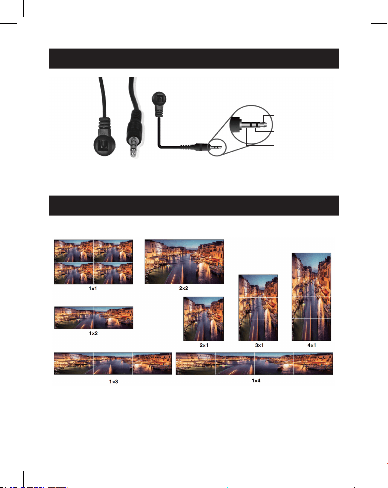
79
8. Assegnazione del pin del cavo IR
9. Video wall
RICEVITORE IR RICEVITORE IR
1
Segnale IR
2
Alimentazione
3
Messa a terra
Il video wall supporta le seguenti otto modalità di splicing:
È possibile impostare la modalità dello schermo tramite i pulsanti sul pannello
frontale, dal telecomando IR o dai comandi RS-232.
Nota: in modalità video wall (eccetto 1x1), solo gli schermi selezionati per eseguire la sovrapposizione
del video wall visualizzeranno le immagini e sarà possibile regolare la cornice.

80
10. Comando di controllo RS-232
Il controller per video wall supporta il controllo dei comandi RS-232. Collegare la
porta RS-232 a un PC con un cavo con connettore Phoenix a 3 pin e un cavo
RS-232-USB. Il metodo di collegamento è il seguente:
Quindi, aprire uno strumento di comando seriale su PC per inviare il comando
ASCII per controllare il dispositivo. L'elenco dei comandi ASCII è mostrato di
seguito.
Comando ASCII
Protocollo della porta seriale. Velocità di trasmissione: 115200 (predenita),
Bit dati: 8, Bit di stop: 1, Bit di controllo: 0
x: Parametro 1, y: Parametro 2, !: Delimitatore
Codice di
comando
Descrizione della
funzione Esempio Feedback
Impostazione
predenita
Impostazione di sistema
help! Elenca tutti i
comandi
help!
r status! Verica lo stato
corrente del
dispositivo
r status! ottenere lo stato
di tutte le unità:
potenza,
modalità video
wall, risoluzione
di uscita
r type! Ricevere il modello
del dispositivo
r type! Controller per
video wall 1x4
r fw version! Ricevere la versione
del rmware
r fw version! versione fw mcu:
x.xx.xx
81
10. Comando di controllo RS-232
Codice di
comando
Descrizione della
funzione Esempio Feedback
Impostazione
predenita
s power z! Accensione/
spegnimento del
dispositivo, z=0~1
(z=0 spegnimento,
z=1 accensione)
s power 1! inizializzazione
del sistema
all'accensione...
inizializzazione
terminata!
versione fw mcu:
x.xx.xx
r power! Verica lo stato di
accensione attuale
r power! accensione/
spegnimento
s reboot! Riavviare il
dispositivo
s reboot! riavvio…
Il sistema di
controllo per
video wall 1x4
è in fase di
inizializzazione...
inizializzazione
terminata!
versione fw mcu:
x.xx.xx
s reset! Ripristino delle
impostazioni
predenite di
fabbrica
Controller per
video wall 1x4
ripristino delle
impostazioni
predenite di
fabbrica
Il sistema di
controllo per
video wall 1x4
è in fase di
inizializzazione...
inizializzazione
terminata!
versione fw mcu:
x.xx.xx
1. Ingresso
HDMI;
2. EDID: 4K@60
4:4:4 2 canali;
3. Disattivazione
mute audio;
4. Modalità video
wall 1x1;
5. Uscita 1080p;
6. Nessuna
rotazione di tutte
le uscite HDMI;
7. H-Bezel=0,
V-Bezel=0;
82
10. Comando di controllo RS-232
Codice di
comando
Descrizione della
funzione Esempio Feedback
Impostazione
predenita
Impostazione dell'input
s input x
edid z!
Imposta la modalità
di input x edid
(x=0~2, z=1~6)
x=0. tutti gli input
x=1. input1 x=2.
input2
z = 1. 4k60, 2.0ch
z=2. 4k60, 5.1ch
z=3. 4k30, 2.0ch z=4.
4k30, 5.1ch z=5.
1080p, 2.0ch
z=6. 1080p, 5.1ch
s input 1
edid 1!
input 1 edid:
4k60, 2.0ch
4k60,2.0ch
r input x edid! Ottenere ingresso
x modalità edid
(x=0~2)
x=0. tutti gli input
x=1. Ingresso HDMI
x=2. Ingresso USB-C
r input 1 edid! HDMI in edid:
4k60, 2.0ch
s output in
source x!
Instradare la fonte
di ingresso verso
l'uscita (x=1~2)
x=1. Ingresso HDMI
x=2. Ingresso USB-C
s output in
source 1!
output->HDMI in output->HDMI in
r output in
source!
Ottieni l'uscita
verticale dalla
sorgente di ingresso
selezionata
r output in
source!
output->HDMI in
Impostazione dell'uscita
s tw mode x! Impostare la
modalità schermo
murale della TV (x =
1~8) x=1. Modalità
1x1 x = 2. Modalità
2x1 x=3. Modalità
3x1 x=4. Modalità
4x1 x=5. Modalità
1x2 x=6. Modalità
1x3 x=7. Modalità
1x4 x=8. Modalità
2x2
s tw mode 1! Modalità TV
schermo murale:
1x1
Modalità TV
schermo murale:
1x1
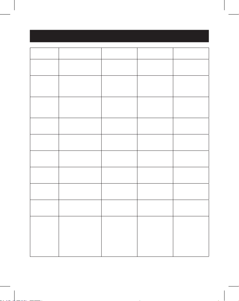
83
10. Comando di controllo RS-232
Codice di
comando
Descrizione della
funzione Esempio Feedback
Impostazione
predenita
r tw mode! Ricevere la modalità
di visualizzazione tv
a parete
r tw mode! modalità
schermo murale:
2x2
s tw h bezel
+!
Impostare la cornice
orizzontale della tv a
parete
s tw h bezel +! cornice
orizzontale
tv a parete:
(cornice+1)
cornice
orizzontale tv a
parete: 0
s tw h bezel -! Impostare la cornice
orizzontale della tv a
parete
s tw h bezel -! cornice
orizzontale
tv a parete:
(cornice-1)
cornice
orizzontale tv a
parete: 0
s tw h bezel x! Impostare la cornice
orizzontale tv a
parete (x=0~10)
s tw h bezel 0! Cornice
orizzontale tv a
parete: 0
Cornice
orizzontale tv a
parete: 0
r tw h bezel! Ricevere la riga della
cornice della tv a
parete
r tw h bezel! cornice
orizzontale tv a
parete: 0
s tw v bezel +! Impostare la cornice
verticale della tv a
parete
s tw v bezel +! cornice verticale
della tv a parete:
(cornice+1)
cornice verticale
tv a parete: 0
s tw v bezel -! Impostare la cornice
verticale della tv a
parete
s tw v bezel -! cornice verticale
della tv a parete
(cornice-1)
cornice verticale
tv a parete: 0
s tw v bezel x! Impostare la cornice
verticale della tv a
parete (x=0~10)
s tw v bezel 0! cornice verticale
tv a parete: 0
cornice verticale
tv a parete: 0
r tw v bezel! Ricevere la cornice
verticale per tv a
parete
r tw v bezel! cornice verticale
tv a parete: 0
s tw res x! Impostare la
risoluzione della tv a
parete (x=1~4)
1.1280x720p60,
2. 1920x1080p60,
3. 3840x2160p30,
4. 1024x768@60
(XGA)
s tw res 2! risoluzione
tv a parete:
1920x1080p60
risoluzione
tv a parete:
1920x1080p60
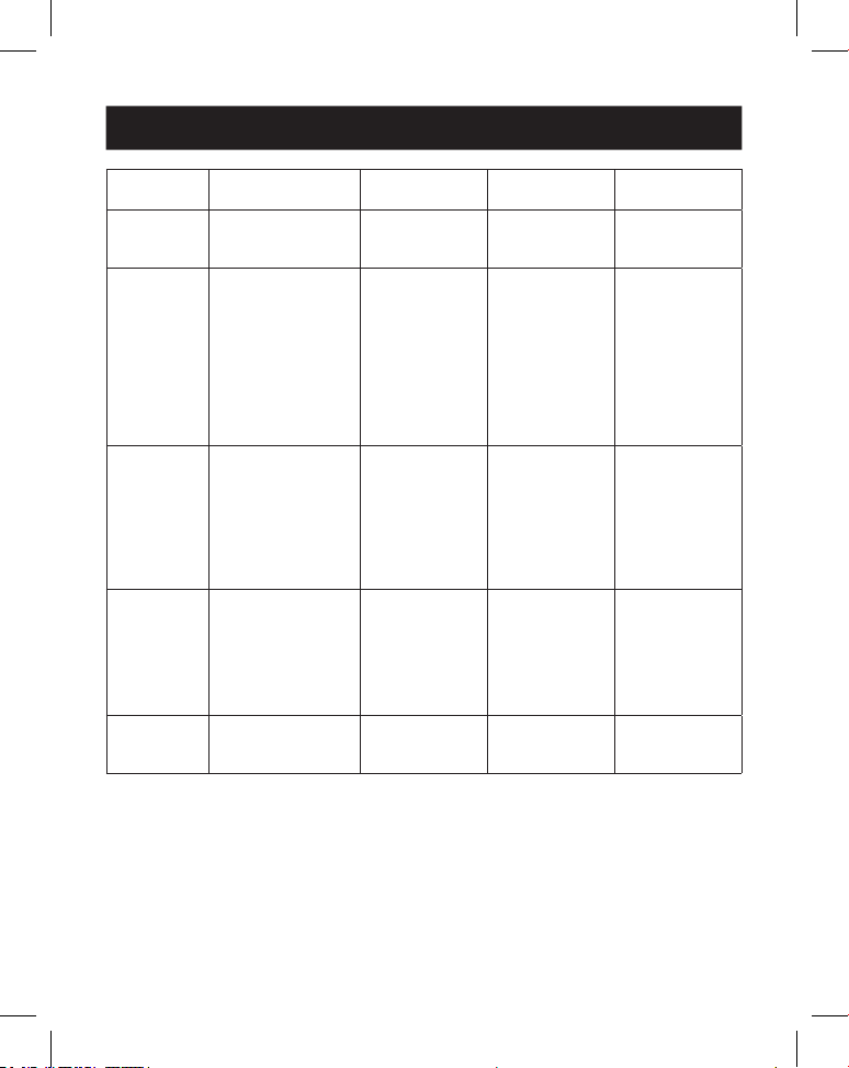
84
10. Comando di controllo RS-232
Codice di
comando
Descrizione della
funzione Esempio Feedback
Impostazione
predenita
r tw res! Ricevere la
risoluzione della
parete tv
r tw res! risoluzione
tv a parete:
1920x1080p60
risoluzione
tv a parete:
1920x1080p60
s output y
rotate x!
Impostare il
mirroring verticale
dell'uscita (y=1~4,
x=0,1)
y=1. uscita 1
y=2. uscita 2
y=3. uscita 3
y=4. uscita 4
x=0. Rotazione 0°
x=1. Rotazione 180°
s output 1
rotazione 0!
output1:
rotazione 0°
output1:
rotazione
0° output2:
rotazione
0° output3:
rotazione
0° output4:
rotazione 0°
r output y
rotation!
Imposta il mirroring
verticale dell'uscita
y (y=0~4) y=0. uscita
tutti y=1. uscita 1
y=2. uscita 2
y=3. uscita 3
y=4. uscita 4
r output 0
rotation!
output1:
rotazione
0° output2:
rotazione
0° output3:
rotazione
0° output4:
rotazione 0°
s output
audio mute x!
Impostare l'audio di
uscita in modalità
silenziosa
attivato/disattivato
(x=0~1)
0. mute o
1. mute on
s output audio
mute 0!
audio in uscita
mute: disattivato
disattivato
r output
audio mute!
Impostare l'audio in
uscita su mute
attivare/disattivare
r output audio
mute!
audio in uscita
mute: disattivato
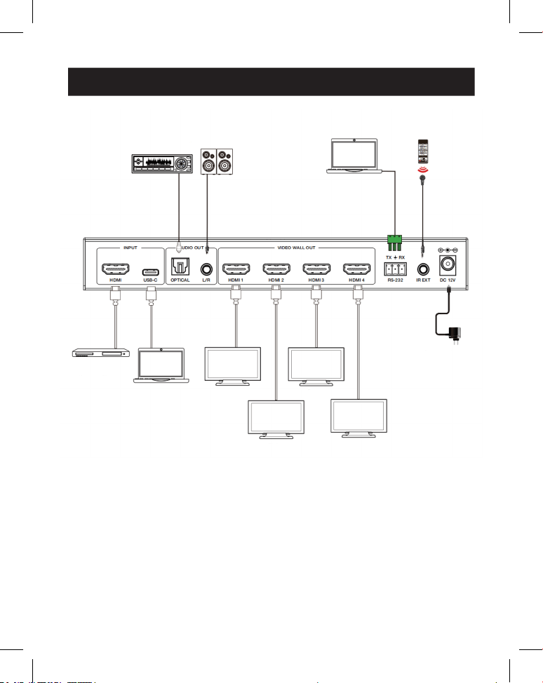
85
11. Esempio di applicazione
Amplificatore
Display 1
Display 2
Display 3
Display 4
Altoparlanti
Computer
portatile
Ricevitore IR
Alimentazione
Server
multime-
diale o
lettore
Blu-ray
Computer
portatile
(con porta
USB-C)

86
12. Garanzia
GARANZIA LIMITATA DI 3 ANNI
Garantiamo che i nostri prodotti sono privi di difetti dei materiali e di fabbricazione per un perio-
do di tre (3) anni dalla data dell'acquisto iniziale. I nostri obblighi ai sensi della presente garanzia
sono limitati alla riparazione o sostituzione (a nostra esclusiva discrezione) di eventuali prodotti
che presentino tali difetti. Visitare la pagina Tripplite.Eaton.com/support/product-returns prima
di inviare qualsiasi apparecchiatura per la riparazione. La presente garanzia non si applica ad
attrezzature danneggiate accidentalmente, per negligenza o errata applicazione o che siano state
in qualsiasi modo alterate o modicate.
SALVO QUANTO QUI PREDISPOSTO, NON FORNIAMO ALCUNA GARANZIA, ESPLICITA O IMPLICI-
TA, INCLUSE LE GARANZIE DI COMMERCIABILITÀ E IDONEITÀ PER UN PARTICOLARE SCOPO. In
alcuni Stati non sono consentite la limitazione o l'esclusione di garanzie implicite; pertanto, in tali
casi, le limitazioni o esclusioni di cui sopra potrebbero non applicarsi all'acquirente.
SALVO QUANTO PREVISTO SOPRA, IN NESSUN CASO SAREMO RESPONSABILI PER DANNI
DIRETTI, INDIRETTI, SPECIALI, INCIDENTALI O CONSEQUENZIALI DERIVANTI DALL'UTILIZZO
DEL PRODOTTO, ANCHE QUALORA FOSSIMO AVVISATI DELLA POSSIBILITÀ DI DETTI DANNI. In
particolare, non siamo responsabili di alcun costo, come la perdita di protti o ricavi, la perdita di
attrezzature, la perdita di utilizzo di attrezzature, la perdita di software, la perdita di dati, i costi
dei sostituti, i reclami di terzi o altro.
Eaton persegue una politica di miglioramento continuo. Le speciche sono soggette a modiche
senza alcun preavviso.

87