Questions? Contact our U.S.-based
Consumer Care at 1-800-654-8483
between 7AM-8PM, M-F, Central Time.
See reverse for easy-to-follow instructions
and exclusive deals.
Please call before
returning to store
CALL
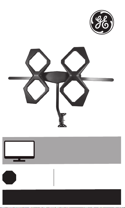
Quadcore HD
Antenna
User Manual

2
WARNING: INSTALLATION OF
THIS PRODUCT NEAR POWER
LINES IS DANGEROUS. FOR
YOUR SAFETY, FOLLOW THE
INSTALLATION DIRECTIONS.
WATCH FOR WIRES! YOU CAN
BE KILLED IF THIS ANTENNA
COMES NEAR ELECTRIC POWER
LINES. READ INSTRUCTIONS!
Instructions made easy

3
TABLE OF CONTENTS
IMPORTANT SAFETY INSTRUCTIONS ....................................................4
SELECT AND MEASURE YOUR INSTALLATION SITE ......................... 5
PARTS LIST ........................................................................................................ 6
ASSEMBLING THE ANTENNA .................................................................... 8
ANTENNA GROUNDING & CONNECTION ........................................ 11
ANTENNA REMOVAL ................................................................................. 14
ANTENNA HELPFUL TIPS .........................................................................15
Instructions made easy
Read instructions or watch easy-to-follow
video. Scan code or visit byjasco.com/48896i

4
IMPORTANT SAFETY INSTRUCTIONS:
• NEVER touch ANYTHING or ANYONE in contact with a
power line. You can be electrocuted. In case of an accident
or emergency, call 911 immediately for help.
• INSPECT your installation site carefully for power lines.
Make sure there is no possibility the antenna, its mounting
structure or your ladder can contact power lines. Consider
what can go wrong during installation.
• KEEP the distance between power lines and the antenna
and its mounting structure at least twice the combined
height of the antenna and mounting structure added
together. In the event the antenna falls during or after
assembly, there must be sufficient distance to ensure it
does not contact the power lines.
• KEEP your ladder, the antenna and antenna mounting
structure (such as mast, pole and mount) far away from
power lines at all times.
• GROUND the antenna and the antenna mounting
structure in accordance with the NEC electrical code, all
state and local electrical code requirements.
• COMPLETE the antenna assembly on the ground.
• DO NOT use a metal ladder or install the antenna on a
windy day. If the antenna or mast starts to fall, do not
attempt to catch the antenna.
• EXERCISE caution when working on a roof.
• APPLY the included danger label to the base of the
antenna mounting structure.
• INFORM others of the danger of touching power lines or
touching other objects in contact with power lines.
• CONTACT a professional installer to install the
antenna if you are unsure how to safely install and
ground this antenna.
• DO NOT use the power inserter and power supply
outdoors. They are rated for indoor use only. Use only the
power supply provided with the antenna.

5
SELECT AND MEASURE YOUR INSTALLATION SITE
When selecting the antenna installation site:
1. Choose a SAFE location far away from power lines. Keep
the distance between power lines and the antenna and its
mounting structure at least 2 times the combined height
of the antenna and its mounting structure. Refer to the
Important Safety Instructions.
2. Determine the location of the broadcast towers in your
area so you can face the antenna elements toward those
towers. Online resources, such as www.antennaweb.org
and www.dtv.gov can help identify the location of
broadcast towers in your area and the channels you can
expect to receive.
3. Check your local city and state building and electrical
codes. Make sure your planned installation is safe and in
compliance with all applicable codes, rules and regulations.
IF YOU ARE UNSURE OR DO NOT FEEL
CAPABLE OF INSTALLING THIS ANTENNA,
CONTACT A PROFESSIONAL INSTALLER.
6
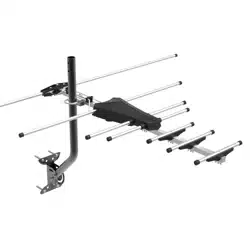
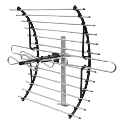
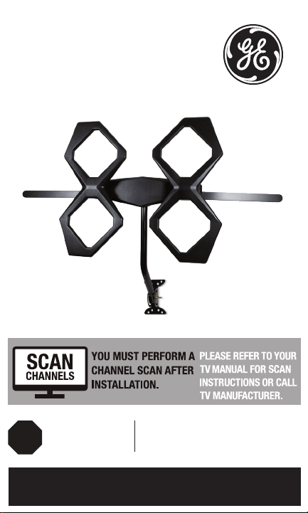
Thank you for purchasing the GE branded Outdoor
Quadcore HD Antenna. This sturdy, high-performance
antenna is designed to receive UHF and VHF broadcast
signals. Its compact design allows you to install it almost
anywhere on your home’s exterior.
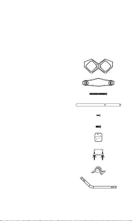
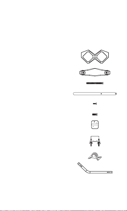
PARTS LIST:
1. Antenna elements (x2)
2. Main housing unit (x1)
3. M5 X 50mm bolts (x4)
4. VHF dipoles (x2)
5. M3 X 8mm bolts (x4)
6. M5 X 12mm bolts (x2)
7. Backplate (x1)
8. U-bolt and clamp assembly (x1)
a. Clamp (x1)
b. U-bolt (x1)
c. Wing nuts (x2)
9. Mounting bracket (x1)
10. J-mount (15/16in. or 2/5cm) (x1)
7
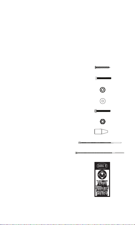
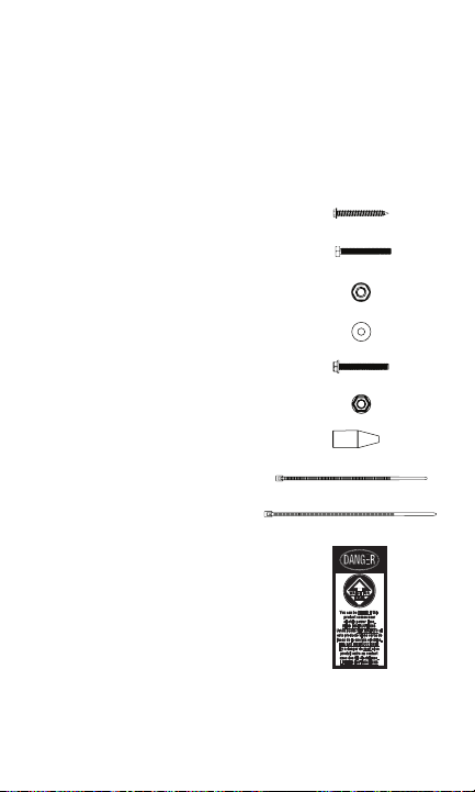
PARTS LIST (CONT.):
11. 2in. X 50.8mm lag screws (x4)
12. M6 X 50mm bolts (x2)
13. M6 locking nuts (x2)
14. M6 washers (x4)
15. M5 X 40mm bolts (x1)
16. M5 nut (x1)
17. Rubber boot (x1)
18. Small zip tie (x1)
19. Large zip tie (x2)
20. Danger label (x1)
8
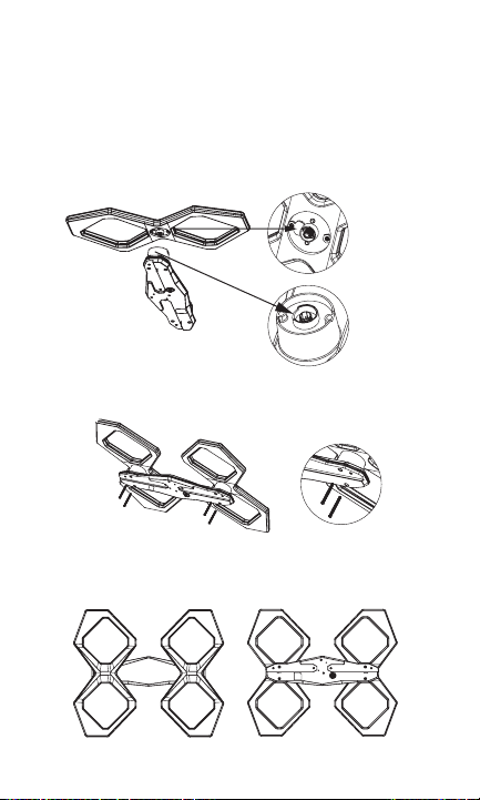
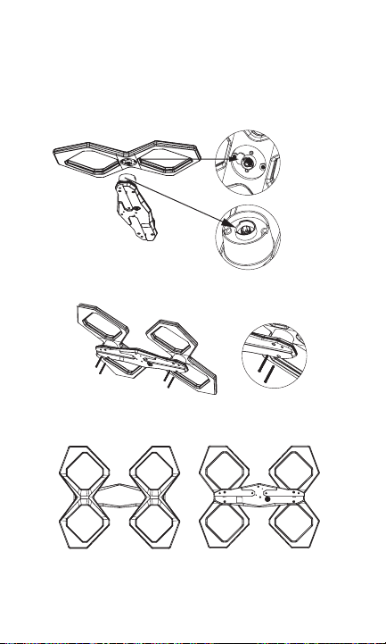
ASSEMBLING THE ANTENNA:
1. Connecting the Antenna Elements to the
Main Housing Unit
a. Connect each antenna element to the main housing
unit by inserting the housing unit’s round protrusions
into the round groove on each antenna element
(Fig. 1a, Fig. 1b & Fig. 1c).
b. Secure with the M5 X 50mm bolts (Fig. 1d & Fig. 1e).
c. After installation (Fig. 1f & Fig. 1g).
(Fig. 1a)
(Fig. 1b)
(Fig. 1c)
(Fig. 1d) (Fig. 1e)
(Fig. 1f front) (Fig. 1g back)
9
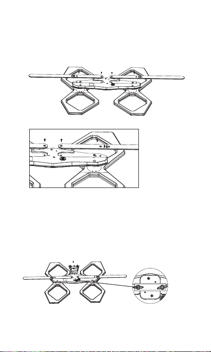
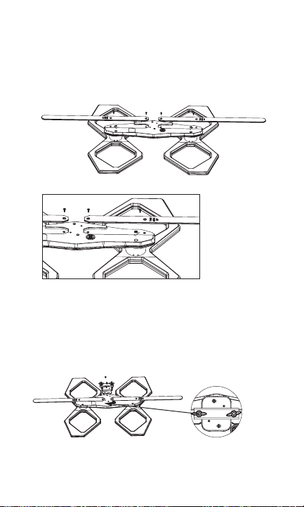
2. Connecting the VHF Dipoles
Place the VHF dipoles in the matching grooves on the
back of the main housing unit, making sure the side of
each dipole marked “THIS SIDE UP” is facing upward.
Secure the dipoles with M3 X 8mm bolts (Fig. 2a & Fig. 2b).
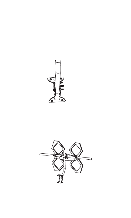
3. Attaching the U-bolt and Clamp Assembly to
the Main Housing Unit
Place the middle of the U-bolt in the groove of the metal
backplate and align the holes on the backplate with the
holes on the main housing unit. Secure the U-bolt in place
with M5 X 12mm bolts (Fig. 3a & Fig. 3b).
(Fig. 2a)
(Fig. 2b)
(Fig. 3a) (Fig. 3b)
10
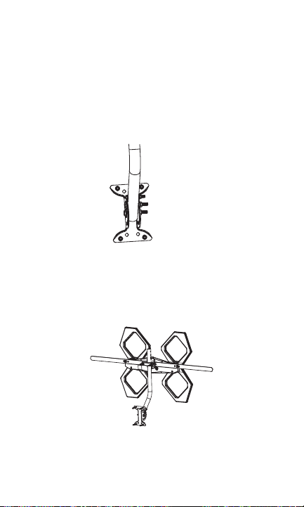
4. Installing the Assembled Antenna
a. Locate a position on the house that is far away from
power lines. Refer to the Important Safety Instructions.
b. Secure the mounting bracket to the location selected
or the antenna. The 2in. X 50.8mm lag screws have
been provided for some installations.
c. Connect the J-mount to the mounting bracket
(Fig. 4a) using the M6 X 50mm bolts, M6 locking nuts
and M6 washers.
d. Position the J-mount perpendicular to the ground using
a small level.
e. Slide the antenna onto the J-mount (Fig. 4b). Face the
antenna elements toward the broadcast towers in your
area. Tighten the wing nuts on the U-bolt when the
antenna is in the desired position.
f. Apply the provided DANGER label to the base of the
mounting structure in a clearly visible location if your
antenna mounting structure, such as a mast, J-mount
or pole, does not already have one.
(Fig. 4a)
(Fig. 4b)
11
ANTENNA GROUNDING & CONNECTION
The National Electric Code (NEC) requires your outdoor antenna
installation to be properly grounded. This involves grounding
the antenna and the antenna mounting structure. This helps
protect you and your property in the event of static buildup on
the antenna or lightning near your home.
NOTE: If you had a satellite or cable system installed at your
home, you may be able to use some parts from this system for
your antenna installation.
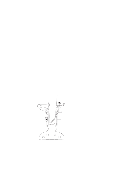
1. Ground the Antenna Mount: Attach a #8 aluminum or a
#10 copper grounding wire to the antenna mounting
structure, such as a pole, mast, tower, etc. In some cases,
a bolt on the mount can be used for making this
connection. When using the provided J-mount, use the M5
bolt and M5 nut in the hole on the J-mount located above
the mounting bracket to make this connection (Fig. 5a).
Tighten this connection securely. Ensure there is a good
electrical connection between your mounting structureand
grounding wire. Run the grounding wire as straight as
possible and use standoff insulators spaced four (4) to
six (6) feet apart. Attach the grounding wire to an
acceptable building ground location. See Grounding Block
How-To for a list of acceptable building ground locations.
(Fig. 5a)
12
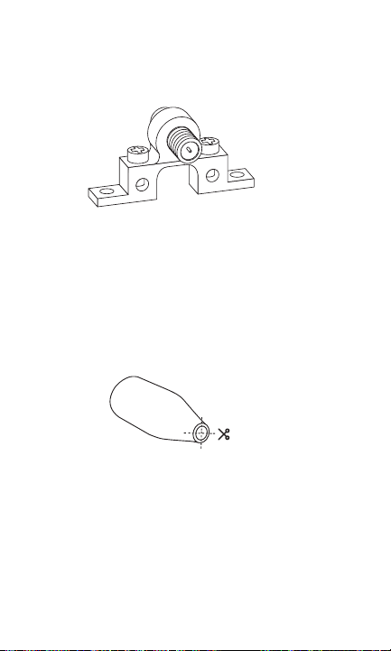
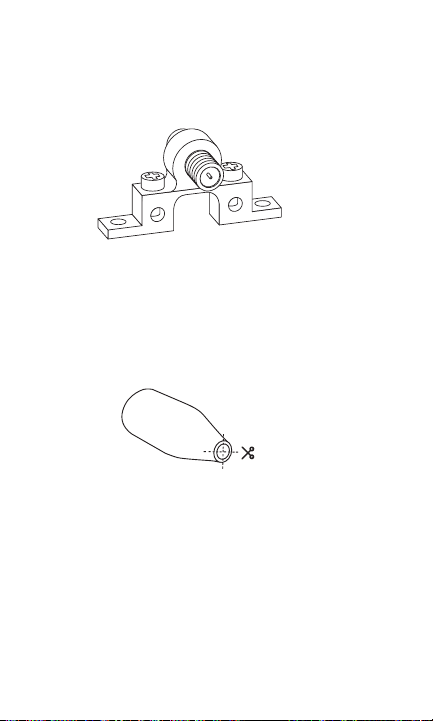
2. Connect the Antenna: Use an outdoor-rated coax cable
to connect the antenna to the 75-ohm grounding block
(not provided). Fig. 5b is an example of a 75-ohm
grounding block. Verify that the grounding block is properly
grounded. See Grounding Block How-To.
If you make your own coax cable, slide the rubber boot
over the cable before you place the connectors on the
cable. Once you have attached the cable to the antenna,
slide the rubber boot into the round channel on the main
housing unit.
If you are using a pre-built cable with connectors,
follow these steps.
a. Cut four slits spaced evenly apart at the narrow tip of
the provided rubber boot, approximately 1/4in.
in length (Fig. 5c).
b. Run the coax cable through the narrow end of the
rubber boot and attach the cable to the antenna.
c. Slide the rubber boot into the round channel on the
main housing unit.
d. Wrap the small zip tie around the slits in the narrow
end of the rubber boot and pull it tight.
From the grounding block, connect an in-wall rated
coax cable that will run through the wall into your home
to an interior cable wallplate connection or, for whole-
home installation, a coaxial splitter in your attic. A separate
(Fig. 5b)
(Fig. 5c)

13
in-wall rated coax cable running to a separate cable
wallplate is required for each location served by the splitter.
The 75-ohm grounding block needs to be placed as close
as possible to the point where the second coax cable
enters your home.
NOTE: Be sure to leave enough slack in the coax cable to
create a drip loop so moisture cannot enter your house.
You will also need to seal the coax cable entry point into
your house with an exterior caulk.
NOTE: Use of multiple splitters in a whole-home
installation will seriously degrade signal quality and is
not recommended.
3. Connect your TV’s antenna port to the coax wallplate
using coaxial cable.
4. Follow your HDTV’s instruction manual to scan for
channels on your TV.
Grounding Block How-To:
Your existing outdoor antenna should already have a properly
installed grounding block in place, but if it must be moved
or is improperly grounded, please follow these important
instructions to ensure your antenna is safely grounded.
1. Connect a #8 aluminum or #10 grounding wire to a
screw terminal on the 75-OHM grounding block.
2. Connect the other end of the wire to an acceptable
building ground location. See examples below.
Examples of acceptable building grounding locations are:
• The building or structure grounding electrode system as
covered in 250.50 in the NEC
• Grounded interior metal water piping system within 5ft.
from its point of entrance to the building
• Grounded, non-flexible metallic power service raceway
• Service equipment enclosure, the grounding electrode
14
conductor or the grounding electrode conductor metal
enclosure of the power service
• An 8ft. grounding rod driven into the ground can be
used as long as it is connected to the central building
ground by a #6 or heavier bonding wire.
Refer to the NEC sections 250 and 810 for other acceptable
grounding methods.
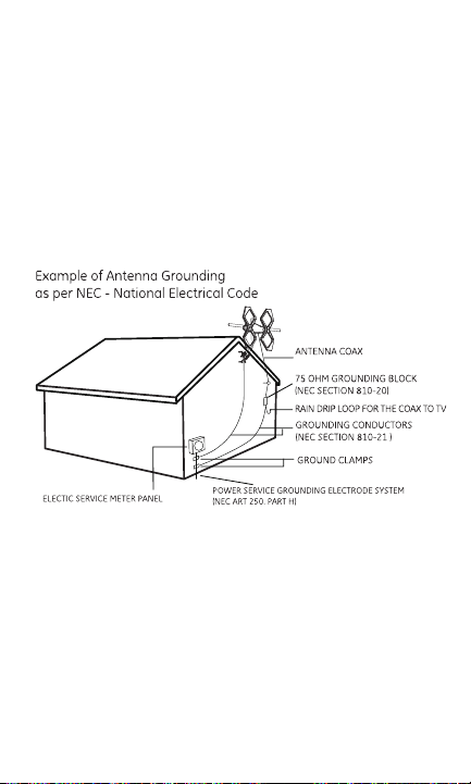
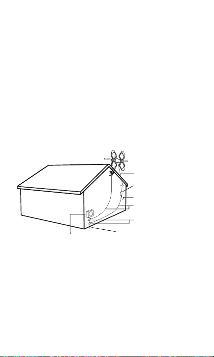
Double-check all your connections after installation is
complete. Ensure there are good electrical connections of your
grounding wires and coax cables. See Fig. 5d for an example of
a properly grounded antenna installation.
IF YOU ARE UNSURE HOW TO PROPERLY GROUND YOUR
ANTENNA INSTALLATION, CONTACT A PROFESSIONAL
INSTALLER IN YOUR AREA.
ANTENNA REMOVAL
Inspect the area carefully for power lines. Look for any new
power lines that may have been installed. Make sure there is no
possibility the antenna, its mounting structure or your ladder
can contact power lines. Consider what can go wrong during
the antenna removal. Repeat the steps for antenna installation
in reverse order.
(Fig. 5d)
-

48896 V1 6/20
MADE IN CHINA
GE is a trademark of General Electric Company and is
under license by Jasco Products Company LLC, 10 E.
Memorial Rd., Oklahoma City, OK 73114.
This Jasco product comes with a limited-lifetime
warranty. Visit www.byjasco.com for warranty details.
Questions? Contact our U.S.-based Consumer Care at
1-800-654-8483 between 7AM -8PM Central Time.
ANTENNA HELPFUL TIPS
Maximize the number of channels by testing the antenna in several
locations. Be sure to run a TV channel scan in each position. Refer to
your TV’s instruction manual if necessary.
For best performance, position or mount the antenna as high as
possible facing the broadcast towers.
Visit www.antennaweb.org or www.dtv.gov to determine the available
television stations and broadcast tower locations in your area.
QUESTIONS? ISSUES?
CALL OUR U.S.-BASED EXPERTS AT
1-800-654-8483
¿Tiene preguntas? Póngase en contacto con
nuestro servicio de atención al consumidor de
EE. UU. al 1-800-654-8483, de lunes a viernes,
de 7 a. m. a 8 p. m. (hora estándar del centro).
Antena
Quadcore HD
DEBE REALIZAR UNA BÚSQUE-
DA DE CANALES DESPUÉS
DE LA INSTALACIÓN.
CONSULTE EL MANUAL
DE SU TELEVISOR PARA
VER LAS INSTRUCCIONES
DE BÚSQUEDA O LLAME AL
FABRICANTE DEL TELEVISOR.
BUSQUE
CANALES
Llámenos antes
de volver a la tienda
LLAME
17
ADVERTENCIA: LA INSTALACIÓN
DE ESTE PRODUCTO CERCA
DEL TENDIDO ELÉCTRICO ES
PELIGROSA. POR SU SEGURIDAD,
SIGA TODAS LAS INSTRUCCIONES
DE INSTALACIÓN.
¡TENGA CUIDADO CON LOS
CABLES! PUEDE MORIR SI ESTA
ANTENA ESTÁ CERCA DE LÍNEAS
DEL TENDIDO ELÉCTRICO. ¡LEA
LAS INSTRUCCIONES!
PELIGRO

18
ÍNDICE
INSTRUCCIONES IMPORTANTES DE SEGURIDAD .............................19
SELECCIONE Y MIDA EL LUGAR DE LA INSTALACIÓN ....................20
LISTA DE PIEZAS ................................................................................................ 21
ENSAMBLAJE DE LA ANTENA ....................................................................23
CONEXIÓN Y PUESTA A TIERRA DE LA ANTENA ................................ 24
RETIRO DE LA ANTENA .................................................................................. 29
CONSEJOS ÚTILES SOBRE LA ANTENA .................................................30

19
INSTRUCCIONES IMPORTANTES DE SEGURIDAD:
• NUNCA toque cualquier OBJETO o PERSONA en contacto
con una línea eléctrica. Puede electrocutarse. En caso de
un accidente o una emergencia, llame inmediatamente
al 911 para pedir ayuda.
• INSPECCIONE detenidamente el lugar de la instalación en
relación con líneas eléctricas. Asegúrese de que no existe
la posibilidad de que la antena, la estructura de montaje
o su escalera puedan tener contacto con líneas eléctricas.
Tenga en cuenta lo que puede salir mal durante la instalación.
• MANTENGA la distancia entre las líneas eléctricas y la antena
y su estructura de montaje de un mínimo del doble de la
suma de la altura combinada de la antena y la estructura de
montaje. En caso de que la antena se caiga durante o después
del montaje, debe haber suficiente distancia para asegurarse
de que no tenga contacto con las líneas eléctricas.
• MANTENGA su escalera, la antena y la estructura de montaje
de la antena (como el mástil, poste y soporte) lejos de las líneas
eléctricas en todo momento.
• CONECTE A TIERRA la antena y la estructura de montaje
de la antena de acuerdo con el código eléctrico NEC, y todos
los requisitos de los códigos eléctricos estatales y locales.
• COMPLETE el montaje de la antena en el suelo.
• NO use una escalera de metal ni instale la antena en un
día ventoso. Si la antena o el mástil comienzan a caerse,
no intente sujetar la antena.
• ACTÚE con prudencia cuando trabaje sobre el techo.
• PEGUE la etiqueta de peligro incluida en la base de la
estructura de montaje de la antena.
• INFORME a las demás personas del peligro de tocar las
líneas eléctricas o tocar otros objetos en contacto con líneas
eléctricas.
• PÓNGASE EN CONTACTO con un instalador profesional para
instalar la antena si no está seguro de cómo instalar esta
antena y conectarla a tierra de forma segura.
• NO use el insertador de potencia y la fuente de alimentación
en exteriores. Están clasificados para uso exclusivo en interiores.
Use únicamente la fuente de alimentación suministrada con

20
SELECCIONE Y MIDA EL LUGAR DE LA INSTALACIÓN
Cuando seleccione el lugar de instalación de la antena:
1. Elija un lugar SEGURO lejos de líneas eléctricas. Mantenga la
distancia entre las líneas eléctricas y la antena y su estructura
de montaje de un mínimo de dos veces la altura combinada de
la antena y la estructura de montaje. Consulte las Instrucciones
importantes de seguridad.
2. Determine la ubicación de las torres de transmisión en su
área para ubicar los elementos de la antena de modo
que estén orientados hacia las torres. Recursos en línea,
como www.antennaweb.org y www.dtv.gov pueden ayudar
a identificar la ubicación de las torres de transmisión en su
área y los canales que puede esperar recibir.
3. Revise los códigos eléctricos y de construcción de su ciudad
y su estado. Asegúrese de que su instalación planificada es
segura y cumple con todos los códigos, normas y reglamentos
aplicables.
SI NO ESTÁ SEGURO O NO SE SIENTE
CAPAZ DE INSTALAR ESTA ANTENA,
PÓNGASE EN CONTACTO CON UN
INSTALADOR PROFESIONAL.
21
Gracias por comprar la Antena exterior Quadcore HD de marca
GE. Esta sólida antena de alto rendimiento está diseñada para
recibir señales de televisión UHF y VHF. Su diseño compacto le
permite instalarla en casi cualquier lugar del exterior de su casa.
LISTA DE PIEZAS:
1. Elementos de la antena (x2)
2. Armazón central (x1)
3. Pernos M5 X 50 mm (x4)
4. Dipolos VHF (x2)
5. Pernos M3 X 8 mm (x4)
6. Pernos M5 X 12 mm (x2)
7. Placa posterior (x1)
8. Conjunto de perno U y abrazadera (x1)
a. Abrazadera (x1)
b. Perno U (x1)
c. Tuercas de mariposa (x2)
9. Soporte para montaje (x1)
10. Soporte curvo J (15/16 in o 2/5 cm) (x1)
22
LISTA DE PIEZAS (CONT.):
11. Tirafondos de 50,8 mm X 50,8 mm (x4)
12. Pernos M6 X 50 mm (x2)
13. Contratuercas M6 (x2)
14. Arandelas M6 (x4)
15. Pernos M5 X 40 mm (x1)
16. Tuerca M5 (x1)
17. Pasacables de goma (x1)
18. Abrazadera plástica pequeña (x1)
19. Abrazadera plástica grande (x2)
20. Etiqueta de peligro (x1)
23
ENSAMBLAJE DE LA ANTENA:
1. Conexión de los elementos de la antena al armazón central
a. Conecte cada elemento de la antena al armazón central
insertando las salientes redondas del armazón central en
la ranura redonda en cada elemento de la antena (Fig. 1a,
Fig. 1b y Fig. 1c).
b. Fije con los pernos M5 X 50 mm (Fig. 1d y Fig. 1e).
c. Después de la instalación (Fig. 1f y Fig. 1g).
2.
(Fig. 1f vista frontal) (Fig. 1g vista posterior)
(Fig. 1e)
(Fig. 1d)
(Fig. 1b)
(Fig. 1c)
(Fig. 1a)
24
Conexión de los dipolos VHF
Coloque los dipolos VHF en las ranuras correspondientes en la
parte posterior del armazón central, asegurándose de que el
lado de cada dipolo marcado “THIS SIDE UP” (este lado hacia
arriba) esté orientado hacia arriba. Fije los dipolos con pernos
M3 X 8 mm (Fig. 2a y Fig. 2b).
3. Fije el conjunto del perno U y la abrazadera al armazón
central
Coloque el medio del perno U en la ranura de la placa
posterior de metal y alinee los orificios en la placa posterior
con los orificios en el armazón central. Fije el perno U en su
lugar con pernos M5 X 12 mm (Fig. 3a y Fig. 3b).
(Fig. 2a)
(Fig. 2b)
(Fig. 3b)
25
4. Instalación de la antena ensamblada
a. Ubique una posición en la vivienda que esté lejos de las
líneas eléctricas. Consulte las Instrucciones importantes
de seguridad.
b. Fije el soporte de montaje a la ubicación seleccionada o a la
antena. Se suministran tirafondos de 50,8 X 50,8 mm para
algunas instalaciones.
c. Conecte el soporte curvo J al soporte de montaje (Fig. 4a)
con los pernos M6 X 50 mm, las contratuercas M6 y las
arandelas M6.
d. Coloque el soporte curvo J de forma perpendicular al suelo
mediante el uso de un nivel pequeño.
e. Deslice la antena en el soporte curvo J (Fig. 4b). Oriente los
elementos de la antena hacia las torres de transmisión en su
área. Apriete las tuercas de mariposa en el perno U cuando
la antena esté en la posición deseada.
f. Pegue la etiqueta de peligro (DANGER) en la base de la
estructura de montaje en un lugar claramente visible si la
estructura de montaje de su antena, como un mástil, soporte
curvo J o poste, no tiene una.
(Fig. 4b)
(Fig. 4a)

26
CONEXIÓN Y PUESTA A TIERRA DE LA ANTENA
El National Electric Code (NEC) exige que la instalación de su antena
exterior esté correctamente conectada a tierra. Esto implica
conectar a tierra la antena y la estructura de montaje de la antena.
De este modo se protege usted mismo y a su propiedad en caso de
acumulación de electricidad estática en la antena o de que caiga
un rayo cerca de su hogar.
NOTA: Si tenía un sistema de satélite o cable instalado en su
vivienda, es posible que pueda usar algunas piezas de este
sistema para la instalación de su antena.
1. Conecte a tierra el soporte de la antena: Fije un cable de
aluminio n.º 8 o de conexión a tierra de cobre n.º 10 a la
estructura de montaje de la antena, como un poste, un mástil o
una torre, etc. En algunos casos, se puede usar un perno en el
soporte para hacer esta conexión. Cuando use el soporte curvo
J, coloque el perno M5 y la tuerca M5 en el orificio del soporte
curvo J ubicado sobre el soporte de montaje para hacer esta
conexión (Fig. 5a).
Apriete bien la conexión. Asegúrese de que haya una buena
conexión eléctrica entre la estructura de montaje y el cable
de conexión a tierra. Extienda el cable de conexión a tierra
de la forma más recta posible y use soportes aisladores
espaciados entre sí con una separación de entre un metro veinte
centímetros (1,20) y un metro ochenta centímetros (1,80). Fije el
cable de conexión a tierra a una ubicación de conexión a tierra
aceptable en la vivienda. Consulte la Guía práctica de conexión
a tierra para ver una lista de ubicaciones de conexión a tierra
aceptables en la vivienda.
(Fig. 5a)
27
2. Conecte la antena: Use un cable coaxial clasificado para exterior
para conectar la antena al bloque de conexión a tierra de 75
ohmios (no provisto). La Fig. 5b es un ejemplo de un bloque
de conexión a tierra de 75 ohmios. Compruebe que el bloque
de conexión a tierra esté conectado a tierra correctamente.
Consulte la Guía práctica de conexión a tierra.
Si elabora su propio cable coaxial, deslice el pasacables de
goma sobre el cable antes de colocar los conectores en
el cable. Cuando haya fijado el cable a la antena, deslice el
pasacables de goma en el canal redondo del armazón central.
Si usa un cable prearmado con conectores, siga estos pasos.
a. Haga cuatro cortes espaciados de manera uniforme en la
punta delgada del pasacables de goma, de unos 6,5 mm
de largo (Fig. 5c).
b. Pase el cable coaxial a través del extremo angosto del
pasacables de goma y conecte el cable a la antena.
c. Deslice el pasacables de goma en el canal redondo del
armazón central.
d. Enrolle la abrazadera plástica pequeña alrededor de los
cortes en el extremo angosto del pasacables de goma
y apriétela fuertemente.
Desde el bloque de conexión a tierra, conecte un cable coaxial
clasificado para uso dentro de muros que recorrerá el muro de
su vivienda hasta una conexión interior de placa de pared para
cables o, en el caso de una instalación para toda la vivienda, un
divisor coaxial en el desván. Se requiere otro cable clasificado
para uso dentro de muros que se extienda hasta una placa de
(Fig. 5b)
(Fig. 5c)

28
pared distinta para cada ubicación alimentada por el divisor. El
bloque de conexión a tierra de 75 ohmios debe ubicarse lo más
cerca posible del punto de ingreso a la vivienda del segundo cable
coaxial.
NOTA: Asegúrese de dejar suficiente cable coaxial para formar
un lazo de goteo y que la humedad no pueda entrar a su
vivienda. También deberá sellar el punto de ingreso del cable
coaxial a su vivienda con una masilla para exterior.
NOTA: El uso de varios divisores en una instalación para toda
la vivienda deteriorará muchísimo la calidad de la señal y no
se recomienda.
3. Use un cable coaxial para conectar el puerto de antena de
su televisor a la placa de pared para cable coaxial.
4. Siga las instrucciones en el manual de su televisor HD para
buscar canales.
Guía práctica de conexión a tierra:
Su actual antena exterior ya debe tener instalado un bloque
de conexión a tierra, pero si debe moverla o si se hizo de forma
incorrecta, siga estas instrucciones importantes para asegurarse
de que la antena esté conectada a tierra de forma segura.
1. Conecte un cable de aluminio n.º 8 o un cable de conexión
a tierra n.º 10 a un terminal de tornillo en el bloque de
conexión a tierra de 75 ohmios.
2. Conecte el otro extremo del cable a una ubicación
de conexión a tierra aceptable en la vivienda. Vea
los siguientes ejemplos.
Ejemplos de ubicaciones de conexión a tierra aceptables en la
vivienda:
• El sistema de electrodos de conexión a tierra del edificio
o la estructura según se indica en el artículo 250.50 de la
norma NEC.
• Sistema interior de cañerías de agua metálicas conectado
a tierra, a 1,5 m (5 ft) de su punto de entrada al edificio.
• Conducto de servicio de energía metálico no flexible
conectado a tierra.
29
• El recinto de equipos de servicio, el conductor de electrodos
de conexión a tierra o el recinto metálico del conductor
de electrodos de conexión a tierra del servicio de energía.
• Se puede usar una barra de conexión a tierra de 2,4 m
(8 ft) anclada en el suelo siempre que esté conectada
a la tierra central del edificio por un cable de conexión
n.º 6 o más grueso.
Consulte las secciones 250 y 810 de la norma NEC para obtener
información sobre otros métodos de conexión a tierra aceptables.
Vuelva a comprobar todas las conexiones después de terminar
la instalación. Asegúrese de que sus cables a tierra y cables
coaxiales tengan buenas conexiones eléctricas. Consulte
la Fig. 5d para ver un ejemplo de una instalación de antena
conectada a tierra correctamente.
SI NO ESTÁ SEGURO DE CÓMO CONECTAR A TIERRA
CORRECTAMENTE SU INSTALACIÓN DE ANTENA, PÓNGASE EN
CONTACTO CON UN INSTALADOR PROFESIONAL EN SU ÁREA.
RETIRO DE LA ANTENA
Inspeccione detenidamente el área en relación con líneas
eléctricas. Busque cualquier línea eléctrica nueva que se pueda
haber instalado. Asegúrese de que no existe la posibilidad de que
la antena, la estructura de montaje o su escalera puedan tener
contacto con líneas eléctricas. Tenga en cuenta lo que puede
salir mal durante el retiro de la antena. Repita los pasos de la
Ejemplo de puesta a tierra de antena de
CABLE COAXIAL DE LA ANTENA
BLOQUE DE CONEXIÓN A TIERRA
DE 75 OHMIOS (SECCIÓN 810-20
DEL NEC)
LAZO DE GOTEO DE LLUVIA PARA
EL CABLE COAXIAL A LA TV
CONDUCTORES DE CONEXIÓN
A TIERRA (SECCIÓN 810-21 DEL NEC)
SISTEMA DE ELECTRODOS DE CONEXIÓN
A TIERRA DEL SERVICIO DE ENERGÍA
PANEL DEL MEDIDOR DEL SERVICIO

HECHO EN CHINA
GE es una marca comercial de General Electric
Company con licencia de Jasco Products Company
LLC, 10 E. Memorial Rd., Oklahoma City, OK 73114.
Este producto de Jasco tiene una garantía limitada
de por vida. Visite www.byjasco.com para conocer
los detalles de la garantía.
¿Tiene preguntas? Comuníquese con nuestro
servicio de atención al consumidor de EE. UU. al
1-800-654-8483, de lunes a viernes, de 7:00 a. m.
a 8:00 p. m. (hora del centro).
CONSEJOS ÚTILES SOBRE LA ANTENA
Maximice la cantidad de canales probando la antena en varios
lugares. Asegúrese de ejecutar una búsqueda de canales de
televisión en cada posición. Consulte el manual de instrucciones
de su televisor si es necesario.
Para un mejor rendimiento, coloque o monte la antena lo más
alto que pueda orientada hacia las torres de transmisión.
Visite www.antennaweb.org o www.dtv.gov para determinar las
emisoras de televisión disponibles y las ubicaciones de las torres
de transmisión en su área.
¿TIENE PREGUNTAS? ¿PROBLEMAS?
LLAME A NUESTROS EXPERTOS EN EE. UU. AL
1-800-654-8483

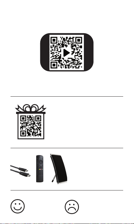
Thank you for your purchase!
Like our product?
Leave a review on your
favorite retailer website
or amazon.com
Having problems?
Let us know how we can help.
Call 1-800-654-8483 between
7AM-8PM, M-F, Central Time.
Enhance your home
entertainment experience
at byjasco.com/ce
For deals, to register your
purchase and to tell us how
we’re doing, simply scan the
code or visit byjasco.com/deals
Exclusive deals
Instructions made easy
Read instructions or watch easy-to-follow
video. Scan code or visit byjasco.com/48896i