Loading ...
Loading ...
Loading ...
73
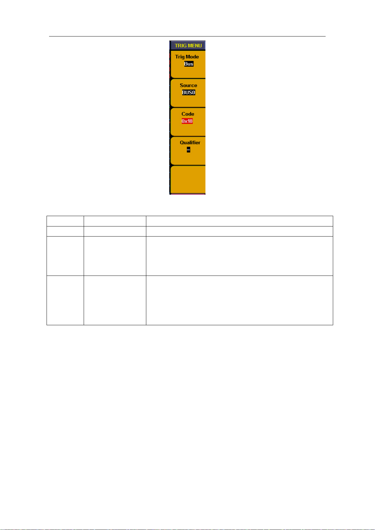
Fig.5-56:Bus trigger menu
Bus trigger menu as below:
Function
Setting
Instruction
Source
BUS0
~
BUS3
BUS0 to BUS3 can be set as trigger source
Code
0x0000
~
0xffff
(HEX)
0~65535
(
DEC
)
Can be set discretionarily between 0x0000 and 0xffff
(HEX)
or between 0 and 65535 (DEC)according to the bus and
code setting.
Qualifier
=
>=
<=
Trigger occur when the Bus value equal to the set code.
Trigger occur when the Bus value is more than or equal to
the set code
Trigger occur when the Bus value is less than or equal to
the set code
For example, to measure an 8 bit data signal we need to observe when data value as 0X18
how the data changed before and after. We set the BUS0 to include CH00~CH07 and use
channel CH00~CH07 to measure the signal. Trigger setting steps as below;
A. Press "Trigger menu" and menu appears.
B. Press "F1" till trigger mode display as "Bus"
C. Press "F2" till signal source display as "BUS0"
D. Press "F3" and data in code type as red background and green digital indicator on, then
insert data value "18" and set code as "0X18". Press "F3" again and red background
disappeared. Repeat operation of step D if setting error or need to be modified,
E. Press "F4" till type display as "="
F. Turn "Trigger level " adjust knob or press "set 50%"till trigger position display as
"NEXT T POS = 50%".
BUS trigger setting is finished and ready for data acquisition (ref to Fig.5-57).
Loading ...
Loading ...
Loading ...