Loading ...
Loading ...
Loading ...
9
4.2 Digital Storage Oscilloscope
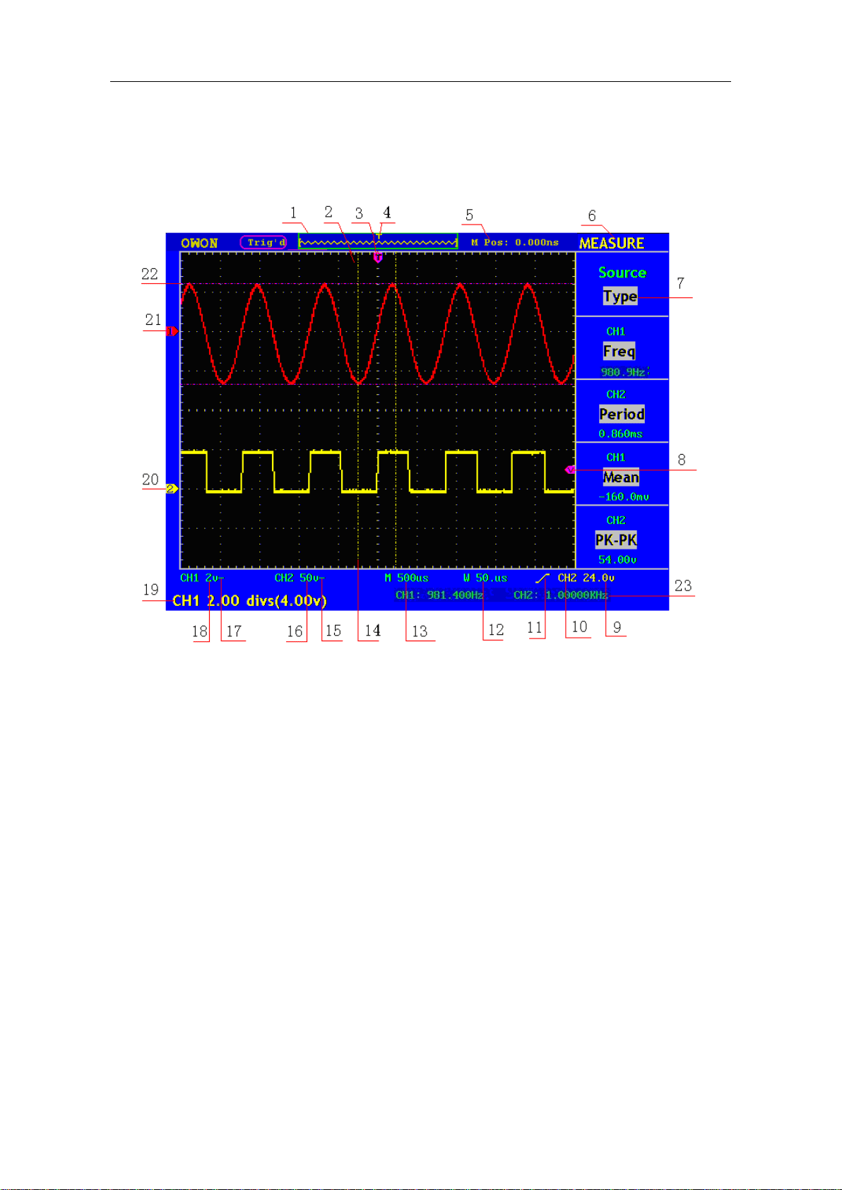
User interface introduction
Fig. 4-3 Illustrative Drawing of Display Interfaces
1. The Trigger State indicates the following information:
Auto: The oscilloscope is under the Automatic mode and is collecting the
waveform under the non-trigger state.
Trig' d: The oscilloscope has already detected a trigger signal and is collecting
the after-triggering information.
Ready: All pre-triggered data have been captured and the oscilloscope has been
already ready for accepting a trigger.
Scan: The oscilloscope captures and displays the waveform data continuously in
the scan mode.
Stop: The oscilloscope has already stopped the waveform data acquisition.
2. Waveform Viewing Area.
3. The purple pointer indicates the horizontal trigger position, which can be adjusted
by the horizontal position control knob.
4. The pointer indicates the trigger position in the internal memory.
Loading ...
Loading ...
Loading ...