Loading ...
Loading ...
Loading ...
11
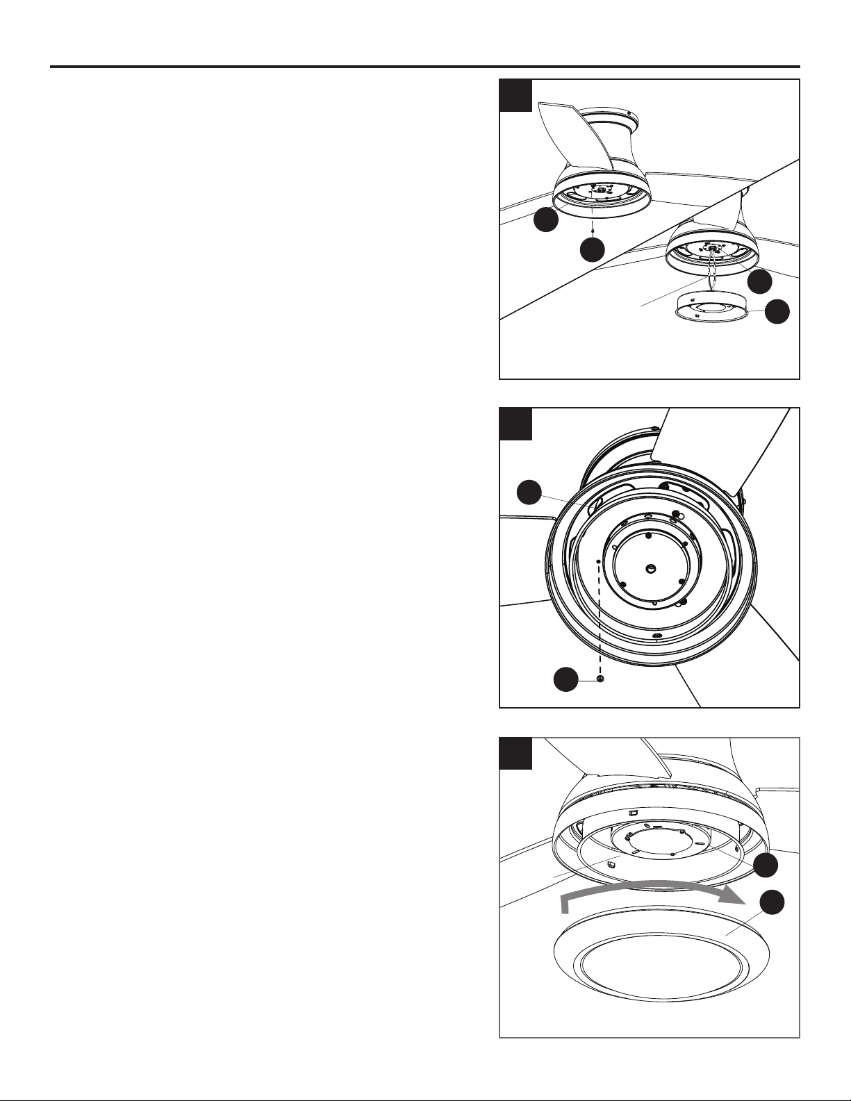
FINAL INSTALLATION
4. Remove one of the switch housing screws (N) from the
light pan (F), and loosen (do not remove) the other two
screws.
Connect the single-pin connector from the center of
the tter plate (D) to the single-pin connector from the
switch housing (E) -- blue to black and white to white.
5. Align the switch housing (E) over the loosened switch
housing screws (N) preassembled on the switch
housing (E), then place the keyholes of the switch
housing (E) onto the switch housing screws (N) and
rotate the switch housing (E) clockwise. Secure the
switch housing (E) with the previously removed switch
housing screw (N). Tighten all three switch housing
screws (N).
6. Align the notches in the switch housing (E) with the
grooves in the locking ring (G) preassembled to bowl
housing (H). Then, twist the locking ring (G) tightly in a
clockwise direction until it is secure.
Turn on the circuit breakers and the wall switch to the
fan supply lead lines.
E
N
5
E
G
6
Notch
4
D
F
E
N
Single-pin connector
Loading ...
Loading ...
Loading ...