Loading ...
Loading ...
Loading ...
24
bromic.com/heat
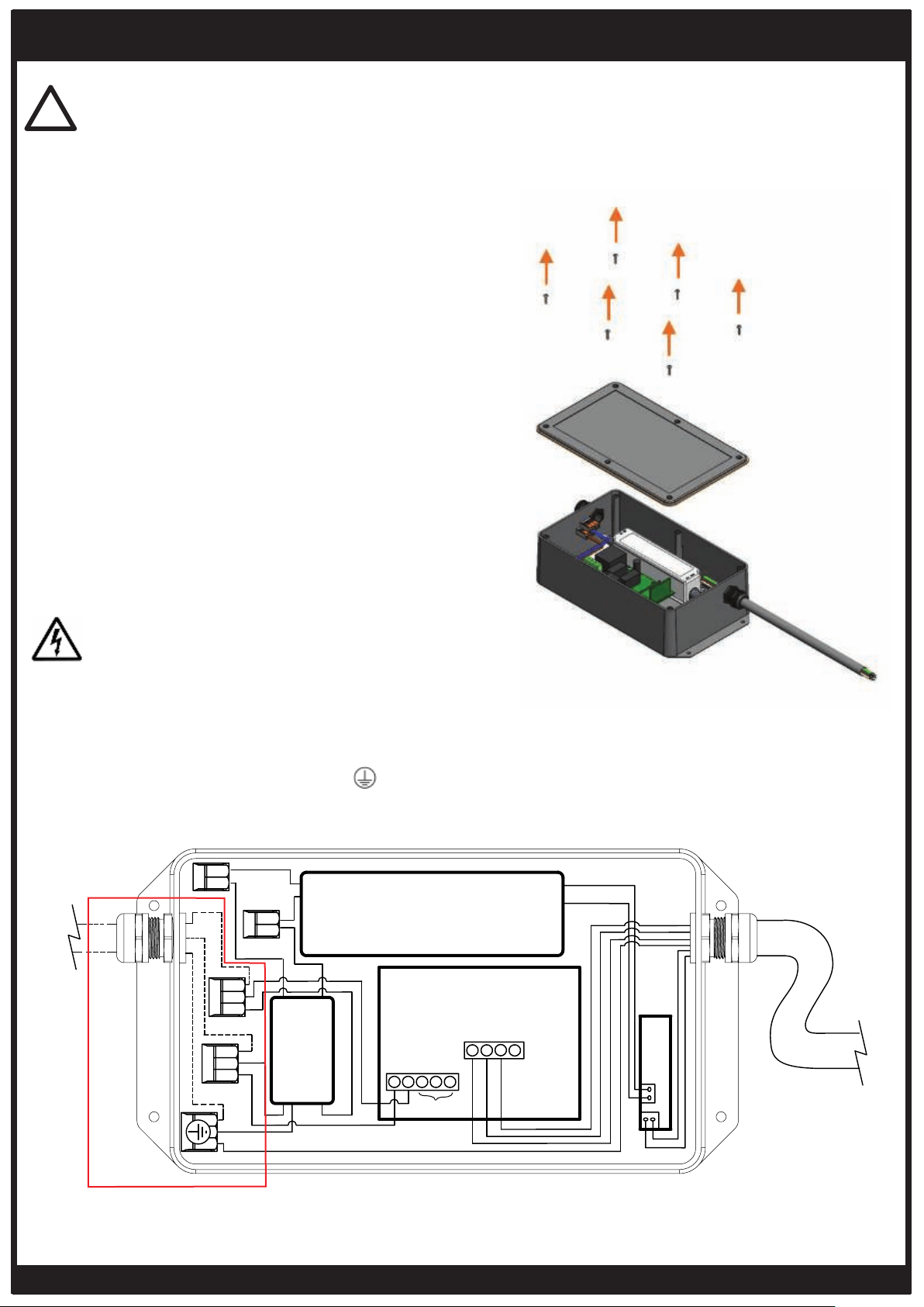
ELECTRICAL INSTALLATION – PENDANT HEATERS CONTROL
1. Open cover to the Pendant Control Box, by
removing 6x Oval head screws (#4-40 -
Length: 1/2”) from the cover.
The Power source MUST NOT be live when
installing the Eclipse Control Box.
DANGER
IMPORTANT
The controller must be installed in a space with free and open air flow which ensures
ambient temperature does not exceed 30°C.
!
TRANSFORMER
MEANWELL (LPF-25-24)
HEATER CONTROL PCB
EMI FILTER
(YB22D1-3A-W)
LED PCB DIMMER
DC OUT 24V
WHITE 24V DC
RED 24V DC
GREEN/YELLOW
GREEN/YELLOW
GROUND
GREY 240V
N/A
N/A
L
L(N)
BLUE
L(N)
BLUE
BLUE
BLUE
BLUE
LINE
LOAD
NEUTRAL
LIVE
BROWN
BROWN
BROWN
BROWN
BLACK 240V
L
G
G
G
L(N)
L
2
3
4
5
6
7
8
9
1
BLACK 24V DC
BROWN 24V DC
AC IN 240V
N
L
2. Wire the power supply (not included) as
per the wiring diagram. The Live, Neutral
and Ground supply wires connect to their
corresponding L, N and Ground WAGO
3-way quick connectors.
Loading ...
Loading ...
Loading ...