Loading ...
Loading ...
Loading ...
• Go to buy.garmin.com, or contact your Garmin dealer for
information about optional accessories and replacement
parts.
Appendix
My Device Displays "Wait for Collar"
If your dog collar device loses GPS signals or cannot
communicate with the handheld device, the handheld device
screen displays Wait for Collar. If this message persists, you
can try these solutions.
• Ensure the dog collar device has acquired satellite signals
(Acquiring Satellite Signals, page 2).
• Ensure the handheld device and the dog collar device have
adequate lines of sight (Communication with the Collar,
page 3).
Restarting the Device
You can restart your device if it stops working.
Hold the power key for 8 seconds.
The device reboots and displays the software version and
ESN of the handheld device.
ANT+
®
Connections
The handheld device uses ANT+ to share dog locations with
Garmin DriveTrack
™
devices and compatible outdoor watches.
The handheld device can transmit to multiple devices at the
same time. For more information about sharing dog locations
with another device, refer to the owner's manual for the device.
NOTE: The handheld device always has ANT+ broadcasting
enabled.
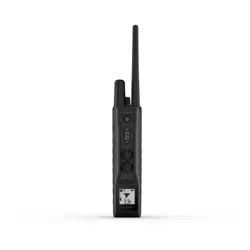
Pro 550 Plus Handheld Device Components
Security screws
Back plate
Battery
Battery connector
Front plate
Gasket
Replacing the Pro 550 Plus Handheld Device
Battery
Before you replace the battery, you must remove all dirt, water,
and debris from the device. You also need a small Phillips
screwdriver and the security screwdriver included with the
battery replacement kit.
1
Remove the eight security screws from the back of the
device.
2
Lift up the back plate.
3
Grip the battery connector wires close to the connector, and
pull the connector perpendicular to the circuit board to
disconnect the battery connector from the device.
4
Grip the rotary switch connector wires close to the connector,
and pull the connector perpendicular to the circuit board to
disconnect the rotary switch connector from the device.
5
Remove the two screws from the battery plate.
6
Lift up the battery plate.
7
Remove the old battery from the back plate, noting the
orientation of the battery.
The battery fits tightly. It may be necessary to pry the battery
out of the back plate using a non-sharp, non-metal object.
8
Install the new battery into the back plate with the label side
up, using the same orientation as the old battery.
The battery orientation is noted graphically inside the back
plate.
9
Replace the battery plate to its original position.
10
Replace and tighten the battery plate screws.
11
With the new battery, connect the battery connector to the
device.
When properly installed, the connector plug snaps into the
port.
12
Reconnect the rotary switch connector to the device.
When properly installed, the connector plug snaps into the
port.
13
Verify the gasket is not damaged and is completely seated in
the groove on the front half of the device.
14
While ensuring the battery and rotary switch wires are not
pinched, hold the back plate and the device firmly together,
and replace all eight security screws without tightening.
15
Verify the back plate and the device are aligned with no gaps.
16
Tighten the screws evenly.
17
Verify the gasket is not sticking out of the device.
Fully charge the device before use. If necessary, calibrate the
compass (Calibrating the Compass on the Handheld Device,
page 4).
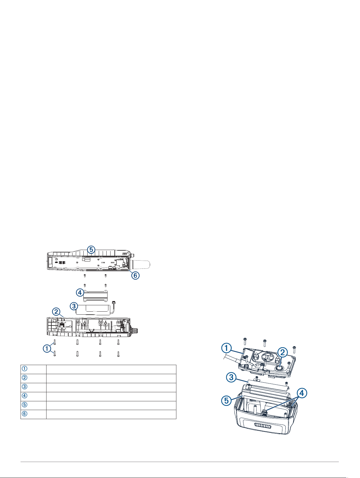
TT 15 Battery Replacement Instructions
TT 15 Components
6 Appendix
Loading ...
Loading ...
Loading ...