Loading ...
INSTRUCTIONS FOR WIRING
Please refer to the installation instructions included with the Humidistat.
Assemble distributor tube sothat it isdirected into the center
openingof the distributor trough cover. Connect 1/4"water
supply tube to brassfilter at inlet ofsolenoid. DO NOT USE
PLASTIC TUBING IN CONTACT WITH ANY HOT
PLENUM SURFACE OR DUCT. IF USING PLASTIC
TUBING, USE TUBE SUPPORT PROVIDED.
Turn on water supply and plug in power cord to check operation of
humidifier. Set humidistat to a demand setting. With the furnace off, the
solenoid valve should be closed and the humidifier fan not running. Start
the furnace, the solenoid valve should open and the humidifier fan run
when the blower or burner circuit is energized. Check flow of water
through distributor trough and evaporator pad. The standard 990-16-76
orifice will supply approximately 3.5 GPH of water at a line water pressure
of 60 psi. For low water pressures (20-40 psi) a larger orifice 990-16-75 is
available to provide the same flow. Leave humidistat set at the
recommended setting.
Connect drain hose to 5/8" spout on humidifier cabinet using hose
clamp provided. Run 5/8" hose to suitable drain such as floor drain,
sewer or laundry sink. Be sure hose has continuous slope and is not
kinked at any point.
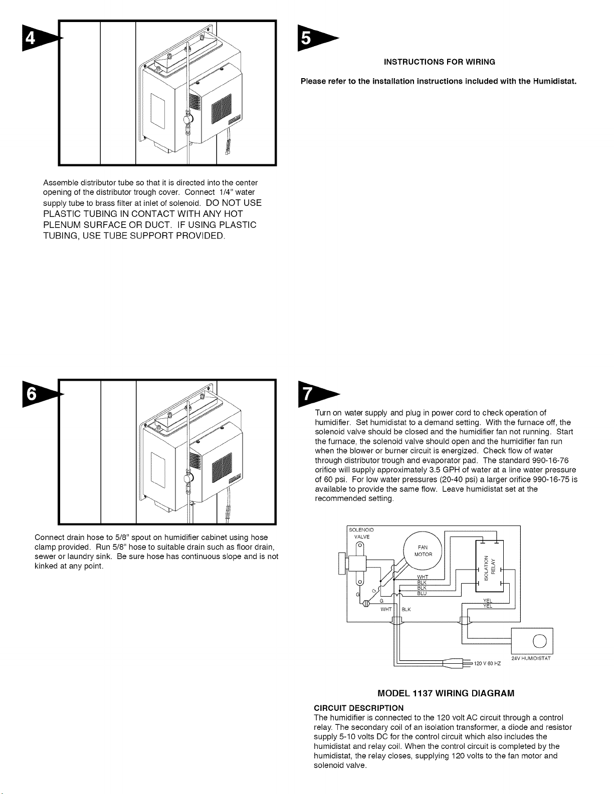
SOLENOID
VALVE _WHT
BLK
BLK
_, BLU
WriT BLK
YEL
._ YEL
i ©
I I_ 120 V 60 HZ 24V HUM]DISTAT
MODEL 1137 WIRING DIAGRAM
CIRCUIT DESCRIPTION
The humidifier is connected to the 120 volt AC circuit through a control
relay. The secondary coil of an isolation transformer, a diode and resistor
supply 5-10 volts DC for the control circuit which also includes the
humidistat and relay coil. When the control circuit is completed by the
humidistat, the relay closes, supplying 120 volts to the fan motor and
solenoid valve.
Loading ...
Loading ...
Loading ...