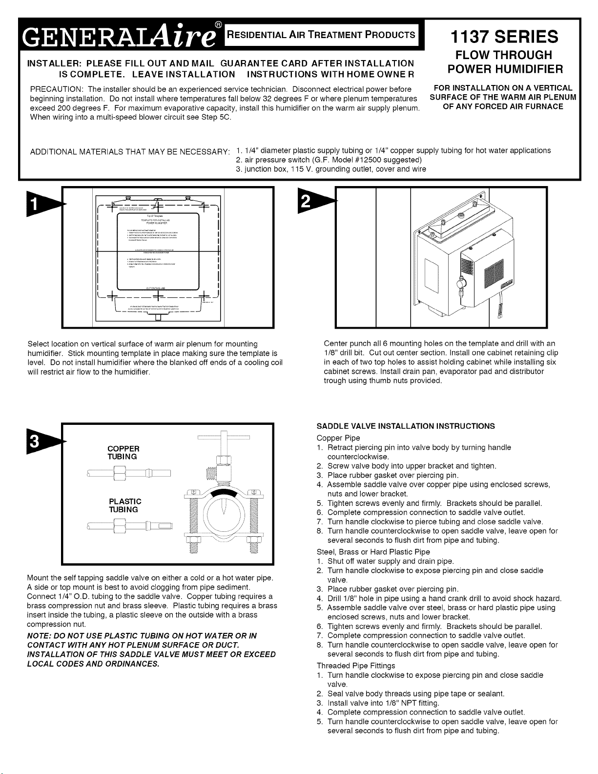
RESIDENTIAL AIR TREATMENT PRODUCTS
INSTALLER: PLEASE FILL OUT AND MAIL GUARANTEE CARD AFTER INSTALLATION
IS COMPLETE. LEAVE INSTALLATION INSTRUCTIONS WITH HOMEOWNER
PRECAUTION: The installer should be an experienced service technician. Disconnect electrical power before
beginning installation. Do not install where temperatures fall below 32 degrees F or where plenum temperatures
exceed 200 degrees F. For maximum evaporative capacity, install this humidifier on the warm air supply plenum.
When wiring into a multi-speed blower circuit see Step 5C.
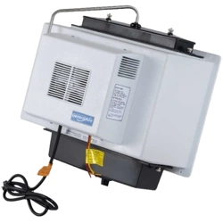
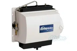
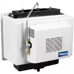
FLOW THROUGH
POWER HUMIDIFIER
FOR INSTALLATION ON A VERTICAL
SURFACE OF THE WARM AIR PLENUM
OF ANY FORCED AIR FURNACE
ADDITIONAL MATERIALS THAT MAY BE NECESSARY: 1.1/4" diameter plastic supply tubing or 1/4" copper supply tubing for hot water applications
2. air pressure switch (G.F. Model #12500 suggested)
3. junction box, 115 V. grounding outlet, cover and wire
Select location on vertical surface of warm air plenum for mounting
humidifier. Stick mounting template in place making sure the template is
level. Do not install humidifier where the blanked off ends of a cooling coil
will restrict air flow to the humidifier.
Center punch all 6 mounting holes on the template and drill with an
1/8" drill bit. Cut out center section. Install one cabinet retaining clip
in each of two top holes to assist holding cabinet while installing six
cabinet screws. Install drain pan, evaporator pad and distributor
trough using thumb nuts provided.
COPPER
TUBING
PLASTIC
TUBI NG
i J
Mount the self tapping saddle valve on either a cold or a hot water pipe.
A side or top mount is best to avoid clogging from pipe sediment.
Connect 1/4" O.D. tubing to the saddle valve. Copper tubing requires a
brass compression nut and brass sleeve. Plastic tubing requires a brass
insert inside the tubing, a plastic sleeve on the outside with a brass
compression nut.
NOTE: DO NOT USE PLASTIC TUBING ON HOT WATER OR IN
CONTACT WITH ANY HOT PLENUM SURFACE OR DUCT.
INSTALLATION OF THIS SADDLE VALVE MUST MEET OR EXCEED
LOCAL CODES AND ORDINANCES.
SADDLE VALVE INSTALLATION INSTRUCTIONS
Copper Pipe
1. Retract piercing pin into valve body by turning handle
counterclockwise.
2. Screw valve body into upper bracket and tighten.
3. Place rubber gasket over piercing pin.
4. Assemble saddle valve over copper pipe using enclosed screws,
nuts and lower bracket.
5. Tighten screws evenly and firmly. Brackets should be parallel.
6. Complete compression connection to saddle valve outlet.
7. Turn handle clockwise to pierce tubing and close saddle valve.
8. Turn handle counterclockwise to open saddle valve, leave open for
several seconds to flush dirt from pipe and tubing.
Steel, Brass or Hard Plastic Pipe
1. Shut off water supply and drain pipe.
2. Turn handle clockwise to expose piercing pin and close saddle
valve.
3. Place rubber gasket over piercing pin.
4. Drill 1/8" hole in pipe using a hand crank drill to avoid shock hazard.
5. Assemble saddle valve over steel, brass or hard plastic pipe using
enclosed screws, nuts and lower bracket.
6. Tighten screws evenly and firmly. Brackets should be parallel.
7. Complete compression connection to saddle valve outlet.
8. Turn handle counterclockwise to open saddle valve, leave open for
several seconds to flush dirt from pipe and tubing.
Threaded Pipe Fittings
1. Turn handle clockwise to expose piercing pin and close saddle
valve.
2. Seal valve body threads using pipe tape or sealant.
3. Install valve into 1/8" NPT fitting.
4. Complete compression connection to saddle valve outlet.
5. Turn handle counterclockwise to open saddle valve, leave open for
several seconds to flush dirt from pipe and tubing.
INSTRUCTIONS FOR WIRING
Please refer to the installation instructions included with the Humidistat.
Assemble distributor tube sothat it isdirected into the center
openingof the distributor trough cover. Connect 1/4"water
supply tube to brassfilter at inlet ofsolenoid. DO NOT USE
PLASTIC TUBING IN CONTACT WITH ANY HOT
PLENUM SURFACE OR DUCT. IF USING PLASTIC
TUBING, USE TUBE SUPPORT PROVIDED.
Turn on water supply and plug in power cord to check operation of
humidifier. Set humidistat to a demand setting. With the furnace off, the
solenoid valve should be closed and the humidifier fan not running. Start
the furnace, the solenoid valve should open and the humidifier fan run
when the blower or burner circuit is energized. Check flow of water
through distributor trough and evaporator pad. The standard 990-16-76
orifice will supply approximately 3.5 GPH of water at a line water pressure
of 60 psi. For low water pressures (20-40 psi) a larger orifice 990-16-75 is
available to provide the same flow. Leave humidistat set at the
recommended setting.
Connect drain hose to 5/8" spout on humidifier cabinet using hose
clamp provided. Run 5/8" hose to suitable drain such as floor drain,
sewer or laundry sink. Be sure hose has continuous slope and is not
kinked at any point.
SOLENOID
VALVE _WHT
BLK
BLK
_, BLU
WriT BLK
YEL
._ YEL
i ©
I I_ 120 V 60 HZ 24V HUM]DISTAT
MODEL 1137 WIRING DIAGRAM
CIRCUIT DESCRIPTION
The humidifier is connected to the 120 volt AC circuit through a control
relay. The secondary coil of an isolation transformer, a diode and resistor
supply 5-10 volts DC for the control circuit which also includes the
humidistat and relay coil. When the control circuit is completed by the
humidistat, the relay closes, supplying 120 volts to the fan motor and
solenoid valve.
|
RESIDENTIAL AIR TREATMENT PRODUCTS I
INSTALLATEUR : VEUILLEZ REMPLIR ET POSTER LA CARTE DE GARANTIE UNE FOIS L'INSTALLATION
TERMINEE. LAISSER LES DIRECTIVES D'INSTALLATION AU PROPRIETAIRE DE LA MAISON,
HUMIDIFICATEUR PUISSANT
A CIRCULATION DIRECTE
MODELE1137
PRECAUTION : L'installateur dolt etre un technicien qualifie et experiment& Couper I'alimentation electrique
avant de commencer I'installation. Ne pas installer I'appareil dans un endroit oQ la temperature peut descendre
sous 0 °C (32 °F) ou si la temperature du plenum depasse 93 °C (200 °F). For maximum evaporative capacity,
install this humidifier on the warm air supply plenum. Lors d'un branchement & un circuit de ventilateur &
plusieurs vitesses, voir I'etape 5C.
POUR L'INSTALLATION SUR UNE
SURFACE VERTICALE DU PLENUM A
AIR CHAUD DE N'IMPORTE QUELLE
CHAUDIF:RE A AIR PULSE
MATERIAUX ADDITIONNELS POUVANT ETRE REQUIS •
1. Tube d'alimentation en plastique de 1/4 po de diametre ou tube d'alimentation en cuivre
de 1/4 po pour les applications pour eau chaude
2. Commutateur de pression d'air (G.F. modele n° 12500 suggere)
3. Bofte de connexion, prise de 115 V avec terre, couvercle et fil
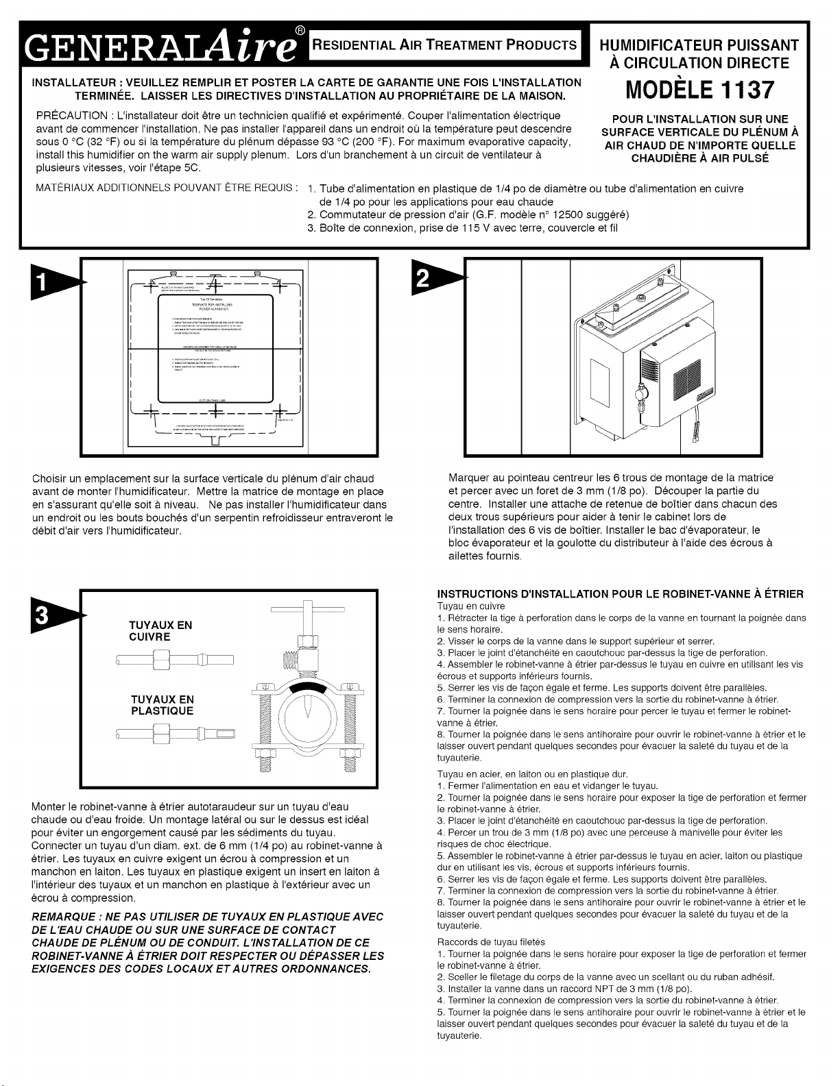
Choisir un emplacement sur la surface verticale du plenum d'air chaud
avant de monter I'humidificateur. Mettre la matrice de montage en place
en s'assurant qu'elle soit & niveau. Ne pas installer I'humidificateur dans
un endroit ou les bouts bouches d'un serpentin refroidisseur entraveront le
debit d'air vers I'humidificateur.
Marquer au pointeau centreur les 6 trous de montage de la matrice
et percer avec un foret de 3 mm (1/8 po). Decouper la partie du
centre. Installer une attache de retenue de boftier dans chacun des
deux trous superieurs pour aider &tenir le cabinet Iors de
I'installation des 6 vis de boftier. Installer le bac d'evaporateur, le
bloc evaporateur et la goulotte du distributeur a I'aide des ecrous
ailettes fournis.
TUYAUX EN
CUIVRE i
TUYAUX EN
PLASTIQUE
Monter le robinet-vanne & etrier autotaraudeur sur un tuyau d'eau
chaude ou d'eau froide. Un montage lateral ou sur le dessus est ideal
pour eviter un engorgement cause par les sediments du tuyau.
Connecter un tuyau d'un diam. ext. de 6 mm (1/4 po) au robinet-vanne &
etrier. Les tuyaux en cuivre exigent un ecrou & compression et un
manchon en laiton. Les tuyaux en plastique exigent un insert en laiton &
I'interieur des tuyaux et un manchon en plastique & I'exterieur avec un
ecrou &compression.
REMARQUE : NE PAS UTILISER DE TUYAUX EN PLASTIQUE AVEC
DE L'EAU CHAUDE OU SUR UNE SURFACE DE CONTACT
CHAUDE DE PLENUM OU DE CONDUIT. L'INSTALLATION DE CE
ROBINET-VANNE A ETRIER DOlT RESPECTER OU DEPASSER LES
EXIGENCES DES CODES LOCA UX ETA UTRES ORDONNANCES.
INSTRUCTIONS D'INSTALLATION POUR LE ROBINET-VANNE .&.I_TRIER
Tuyau en cuiwe
1. Retracter la tige a.perforation dans le corps de la vanne en tournant la poignee dans
le sens horaire.
2. Visser le corps de la vanne dans le support superieur et setter.
3. Placer le joint d'etancheite en caoutchouc par-dessus la tige de perforation.
4. Assembler le robinet-vanne a etrier par-dessus le tuyau en cuivre en utilisant les vis
ecrous et supports inferieurs foumis.
5. Serrer les vis de fa?on egale et ferme. Les supports doivent _tre paralleles.
6. Terminer la connexion de compression vers la sortie du robinet-vanne a etrier.
7. Tourner la poignee dans le sens horaire pour percer le tuyau et fermer le robinet-
vanne a.etrier.
8. Toumer la poignee dans le sens antihoraire pour ouvrir le robinet-vanne a etrier et le
laisser ouvert pendant quelques secondes pour evacuer la salete du tuyau et de la
tuyauterie.
Tuyau en acier, en laiton ou en plastique dur.
1. Fermer I'alimentation en eau et vidanger le tuyau.
2. Toumer la poignee dans le sens horaire pour exposer la tige de perforation et fermer
le robinet-vanne a.etrier.
3. Placer le joint d'6tancheite en caoutchouc par-dessus la tige de perforation.
4. Percer un trou de 3 mm (1/8 po) avec une perceuse a manivelle pour eviter les
risques de choc electrique.
5. Assembler le robinet-vanne a etrier par-dessus le tuyau en acier, laiton ou plastique
dur en utilisant les vis, ecrous et supports inferieurs foumis.
6. Serrer les vis de fa?on egale et ferme. Les supports doivent _tre paralleles.
7. Terminer la connexion de compression vers la sortie du robinet-vanne a etrier.
8. Toumer la poignee dans le sens antihoraire pour ouvrir le robinet-vanne a etrier et le
laisser ouvert pendant quelques secondes pour evacuer la salete du tuyau et de la
tuyauterie.
Raccords de tuyau filetes
1. Toumer la poignee dans le sens horaire pour exposer la tige de perforation et fermer
le robinet-vanne a.etrier.
2. Sceller le filetage du corps de la vanne avec un scellant ou du ruban adhesif.
3. Installer la vanne dans un raccord NPT de 3 mm (1/8 po).
4. Terminer la connexion de compression vers la sortie du robinet-vanne a etrier.
5. Toumer la poignee dans le sens antihoraire pour ouvrir le robinet-vanne a etrier et le
laisser ouvert pendant quelques secondes pour evacuer la salete du tuyau et de la
tuyauterie.
INSTRUCTIONS POUR LE C.&.BLAGE
Veuillez consulter la notice d'installation fournie avec I'humidistat.
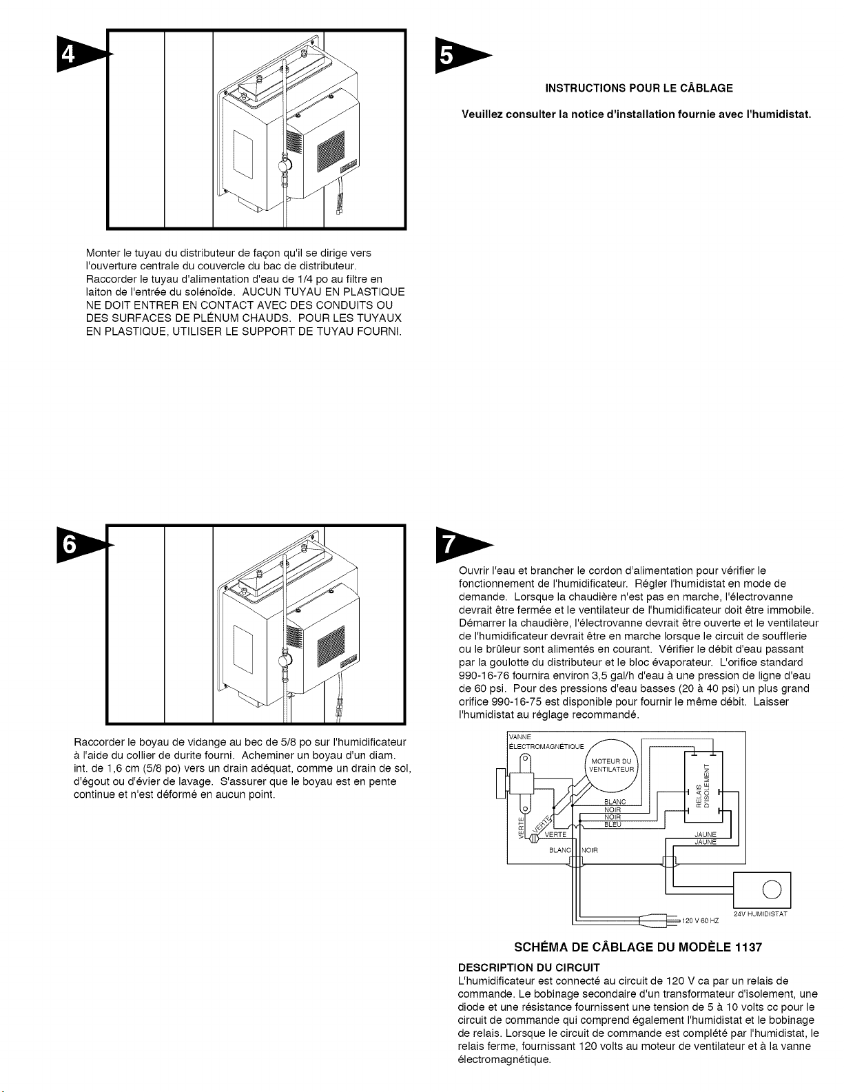
Monter le tuyau du distributeur de fa£on qu'il se dirige vers
I'ouverture centrale du couvercle du bac de distributeur.
Raccorder le tuyau d'alimentation d'eau de 1/4 po au filtre en
laiton de I'entree du solenofde. AUCUN TUYAU EN PLASTIQUE
NE DOlT ENTRER EN CONTACT AVEC DES CONDUITS OU
DES SURFACES DE PLENUM CHAUDS. POUR LES TUYAUX
EN PLASTIQUE, UTILISER LE SUPPORT DE TUYAU FOURNI.
Raccorder le boyau de vidange au bec de 5/8 po sur I'humidificateur
& I'aide du collier de durite fourni. Acheminer un boyau d'un diam.
int. de 1,6 cm (5/8 po) vers un drain adequat, comme un drain de sol,
d'egout ou d'evier de lavage. S'assurer que le boyau est en pente
continue et n'est dBforme en aucun point.
Ouvrir I'eau et brancher le cordon d'alimentation pour verifier le
fonctionnement de I'humidificateur. Regler I'humidistat en mode de
demande. Lorsque la chaudiere n'est pas en marche, I'electrovanne
devrait etre fermee et le ventilateur de I'humidificateur doit etre immobile.
Demarrer la chaudiere, I'electrovanne devrait etre ouverte et le ventilateur
de I'humidificateur devrait etre en marche Iorsque le circuit de soufflerie
ou le brQleur sont alimentes en courant. Verifier le debit d'eau passant
par la goulotte du distributeur et le bloc evaporateur. L'orifice standard
990-16-76 fournira environ 3,5 gal/h d'eau & une pression de ligne d'eau
de 60 psi. Pour des pressions d'eau basses (20 & 40 psi) un plus grand
orifice 990-16-75 est disponible pour fournir le meme debit. Laisser
I'humidistat au reglage recommand&
VANNE
ELECTROMAGNETIQUEw BLANCNoIRNOIR
BLEU
JAUNE
40
ii, 1_:::==120veoHz 24vHUMIDISTAT
SCHI:!:MADE C.&BLAGE DU MODI=LE 1137
DESCRIPTION DU CIRCUIT
L'humidificateur est connecte au circuit de 120 V ca par un relais de
commande. Le bobinage secondaire d'un transformateur d'isolement, une
diode et une resistance fournissent une tension de 5 & 10 volts cc pour le
circuit de commande qui comprend egalement I'humidistat et le bobinage
de relais. Lorsque le circuit de commande est complete par I'humidistat, le
relais ferme, fournissant 120 volts au moteur de ventilateur et & la vanne
electromagnetique.
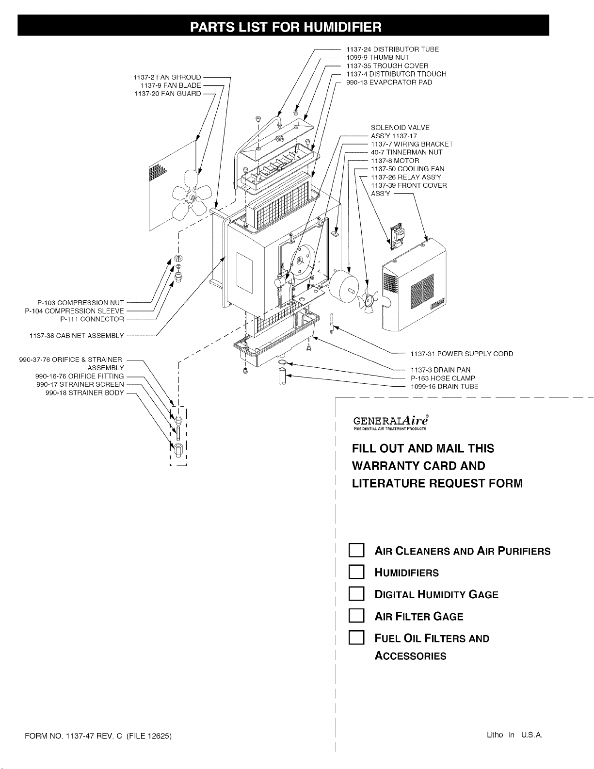
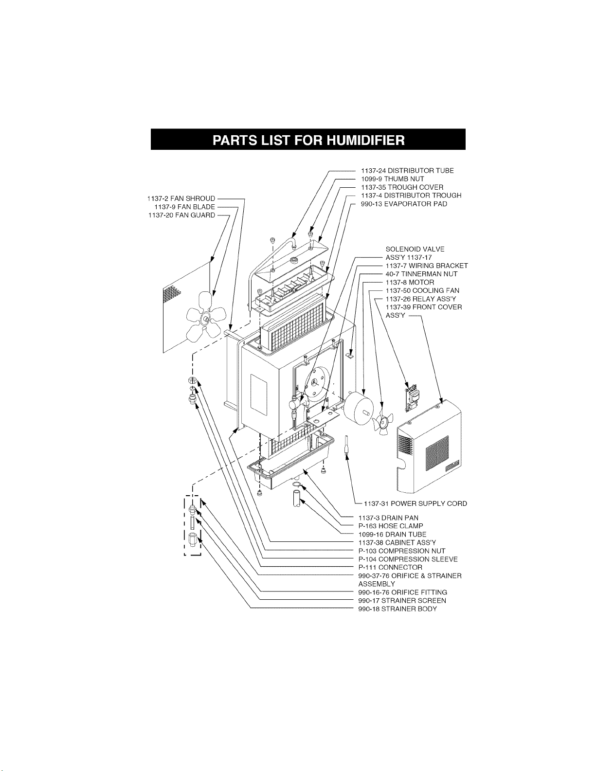
1137-2 FAN SHROUD --
1137-9 FAN BLADE --
1137-20 FAN GUARD
1137-24 DISTRIBUTOR TUBE
1099-9 THUMB NUT
1137-35 TROUGH COVER
1137-4 DISTRIBUTOR TROUGH
990-13 EVAPORATOR PAD
SOLENOID VALVE
-- ASS'Y 1137-17
-- 1137-7 WIRING BRACKET
-- 40-7 TINNERMAN NUT
i 1137-8 MOTOR
1137-50 COOLING FAN
1137-26 RELAY ASS'Y
1137-39 FRONT COVER
ASS'Y --
P-103 COMPRESSION
P-104 COMPRESSION
P-111 CONNECTOR
1137-38 CABINET ASSEMBLY / /
./
J
990-37-76 ORIFICE & STRAINER \ . /
ASSEMBLY \ [
i
990-16-76 ORIFICE FITTING _ X I
990-17 STRA NER SCREEN _X X
990-18 STRAINER BODY ___
FORM NO. 1137-47 REV. C (FILE 12625)
1137-31 POWER SUPPLY CORD
1137-3 DRAIN PAN
P-163 HOSE CLAMP
1099-16 DRAIN TUBE
GENERAIAir_
RESIDENTIAL AIR TREATMENT PRODUCTS
FILL OUT AND MAIL THIS
WARRANTY CARD AND
LITERATURE REQUEST FORM
D AIR CLEANERS AND AIR PURIFIERS
D HUMIDIFIERS
[_ DIGITAL HUMIDITY GAGE
[_ AIR FILTER GAGE
D FUEL OIL FILTERS AND
ACCESSORIES
Litho in U.S.A.
Thishumidifier,ifproperlyregisteredbythereturnofthewarrantyregistrationcardtothemanufacturer,iswarrantedtotheconsumeragainstdefectsin
materialsandworkmanshipforaperiodofoneyearfromthedateofinstallation.Evaporatorpads,sleevesorplatesarenotcoveredbythislimited
warrantyoranyotherwarranties.Anyotherdefectivepartswillberepairedwithoutchargeexceptforremoval,reinstallationandtransportationcosts.To
obtainrepairserviceunderthislimitedwarranty,theconsumermustsendthedefectivepartorthecompletehumidifiertothemanufacturer.
THEREARENOEXPRESSWARRANTIESCOVERINGTHISHUMIDIFIEROTHERTHANASSETFORTHABOVE,THEIMPLIEDWARRANTIESOF
MERCHANTABILITYANDFITNESSFORAPARTICULARPURPOSEARELIMITEDINDURATIONTOONEYEAR.THEMANUFACTURER
ASSUMESNOLIABILITYtNCONNECTIONWITHTHEINSTALLATIONORUSEOFTHISPRODUCT,EXCEPTASSTATEDtNTHISLIMITED
WARRANTY.THEMANUFACTURERWILLINNOEVENTBELIABLEFORINCIDENTALORCONSEQUENTIALDAMAGES.
Thislimitedwarrantygivesyouspecificlegalrights,andyoumayalsohaveotherrightswhichvaryfromstatetostate.Somestatesdonotalloweither
limitationsonimpliedwarranties,orexclusionsfromincidentalorconsequentialdamages,sotheaboveexclusionandlimitationmaynotapplytoyou.
Anyquestionspertainingtothislimitedwarrantyshouldbeaddressedtothemanufacturer.(U.S.A.:Themanufacturerhaselectednottomakeavailable
theinformaldisputesettlementmechanismwhichisspecifiedintheMagnuson-MossWarrantyAct.)
GENERALFILTERS,INC. 43800 GRAND RIVER AVE. NOVI, MICHIGAN 48375-1115 WWW.GENERALAIRE.COM
CANADIAN GENERAL FILTERS, LTD. 39 CROCKFORD BLVD. SCARBOROUGH, ONTARIO M1R3B7
Your Humidifier is engineered to give helpful and trouble-free humidification. For maximum efficiency the following cleaning procedures should be carried
out at the end of each heating season:
1. Turn off water supply and electrical power to humidifier.
2. Remove water distributor tube, distributor trough, evaporator pad and drain pan. The evaporator pad may be
AT
removed from either the top or bottom of the humidifier. Clean excessive mineral deposits from the distributor trough, OUTSIDE RECOMMENDED
cover, drain pan and humidifier cabinet. A solution of 1/2 vinegar & 1/2 water will help loosen mineral deposits. TEMPERATURE SETTING
3. If the evaporator pad has excessive mineral deposits, replace with a new "990-13" evaporator pad. Install trough
and drain pan. Replace cover and the distributor tube to proper position over the distributor trough. -20"_ -29"_0 15%
4. In heavy mineral areas or if the solenoid valve fails to function disconnect the 1/4" water supply line from the
-10",F -23"_0 20%
solenoid valve. Remove the brass strainer body (P.N. 990-18) from the solenoid valve. Carefully pull the strainer
screen (P.N. 990-17) from the orifice fitting (P.N. 990-16). Clean the mineral deposits from all parts, tf the orifice is 0"_ -18"_0 25%
clogged, it may be opened by inserting a small needle. Reinsert the filter into the orifice fitting and screw the brass +10",F -29"_0 30%
strainer body into the solenoid valve.
5. Reconnect the 1/4" water line to the solenoid valve if necessary. Turn on the water supply and check all points for +20"_ - _ 35%
leakage. The operation of the unit may be checked by starting the furnace. The humidifier operates only when the +30"_ - 1"_0 40%
furnace blower is running or the burner circuit is energized. The humidifier is now ready for operation.
6. During the summer, turn off water supply and electrical power to humidifier.
>O E_ < qO 3>00 Z E3 < C) _> 03 ZOc_
o
_-< _ q _- _3z_
m ,,
"
m m D _ :'D 0"]
•
z
Z
r
F
0
Z
r
F
0
Z
Z_
C m
m, >
r
0 Z
m
N
•_ m
O
o
0"13
0 0
F-
• r'rl
Q- --N"
xl_0
m
O
(D
C)"O
O O
O_ 09
r
°
mr- _,;_1 O
==
m r- --'_. Z C_
_0,_ -- CO
mm _)
m
O'u
z r-- NJ
rn>
r-
m
b
N
N1
The operating principle of the humidifier is based on the most efficient and
economical means of evaporating water to the air. The heat necessary for
evaporating water is produced by the furnace.
The water supply to the humidifier is controlled by the electric solenoid valve.
The solenoid valve and humidifier fan are controlled by a humidistat connected
through an isolation relay. The humidistat is designed for wall mounting in the
living area or surface mounting on the return air duct. ELECTRICAL RATING: 24
VAC / 60
z
DO NOT SET RELATIVE HUMIDITY TOO HIGH DURING COLD WEATHER.
EXCESSIVE HUMIDITY MAY CAUSE CONDENSATION ON WINDOWS OR IN
WALLS. REFER TO RECOMMENDED SETTINGS AS DESCRIBED IN THE
HUMIDISTAT OWNERS MANUAL.
Water flows through a strainer, is metered through an orifice to provide the
proper amount of water, and is supplied to the evaporator pad by the distributor
trough. Air from the warm air plenum is pulled through the wetted evaporator pad
by the humidifier fan and returned to the warm air plenum to be circulated through
the living area. Moisture is evaporated to the air passing through the evaporator
pad.
Minerals are not blown into the air stream as occurs in atomizing humidifiers;
they are left on the evaporator pad where a high percentage is carried off with the
waste water.
When the humidifier is installed and operating, no adjustments are necessary
other than setting the control knob on the humidistat to the desired level of
humidification.
To turn the humidifier off, close water supply valve, switch electrical power off
and turn humidistat off.
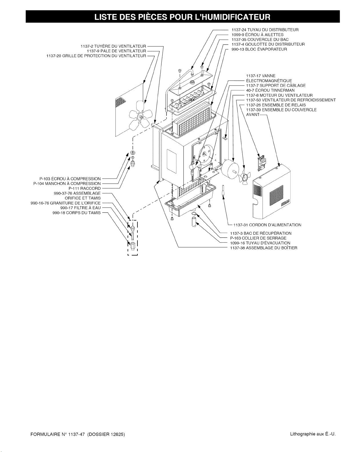
1137-2TUYEREDUVENTILATEUR--
1137-9PALEDEVENTILATEUR--
1137-20GRILLEDEPROTECTIONDUVENTILATEUR
1137-24TUYAUDUDISTRIBUTEUR
1099-9ECROUAAILETTES
1137-35COUVERCLEDUBAC
1137-4GOULOTTEDUDISTRIBUTEUR
990-13BLOCEVAPORATEUR
1137-17VANNE
-- ELECTROMAGNETIQUE
-- 1137-7SUPPORTDECABLAGE
-- 40-7ECROUTINNERMAN
i 1137-8 MOTEUR DU VENTILATEUR
1137-50 VENTILATEUR DE REFROIDISSEMENT
1137-26 ENSEMBLE DE RELAIS
1137-39 ENSEMBLE DU COUVERCLE
/ j
¢
i
I
P.lO3ECROUACOMPRESS,ON
P-104 MANCHON A COMPRESSION
P-111 RACCORD --
990-37-76 ASSEMBLAGE
ORIFICE ET TAMIS
990-16-76 GRANITURE DE L'ORIFICE /. "
990-17 FILTRE A EAU "/
990-18 CORPS DU TAMIS /" "
_1137-31
CORDON D'ALIMENTATION
1137-3 BAC DE RECUPERATION
P-163 COLLIER DE SERRAGE
1099-16 TUYAU D'EVACUATION
1137-38 ASSEMBLAGE DU BO/TIER
FORMULAIRE N° 1137-47 (DOSSIER 12625) Lithographie aux E.-U.
Cethumidificateur,s'ilestenregistr@correctementenretournantlacarted'enregistrementdelagarantieaufabriquant,estgarantiauconsommateur
contretoutd@fautdemat@riauxetdemaind'oeuvrepourunep@riodedeun(1)an&partirdeladated'installation.Lesblocs@vaporateuroulesplaques
nesontpascouvertsparcettegarantielimit@eoupartouteautregarantie.Touteautrepieced@fectueuseserarepar@esansfrais,hormislescoQtsde
d@sinstallation,der@installationetdetransport.Pourobtenirunserviceder@parationaveccettegarantielimit@e,leconsommateurdoitenvoyerlapiece
defectueuseouI'humidificateuraucompletaufabricant.
AUCUNEAUTREGARANTIEQUELAPRESENTENECOUVRECETHUMIDIFICATEUR,LESGARANTIEStMPLtCtTESDEQUALITEMARCHANDE
OUD'ADAPTATION,AUNUSAGEPARTICULtERSONTLIMITEES,AUN(1)AN.LEFABRtCANTNEPEUTETRETENURESPONSABLEPOUR
L'INSTALLATIONOUL'UTILISATIONDECEPRODUIT,SAUFDELAMANIEREtNDIQUEEDANSLAPRESENTEGARANTtELtMITEE.LE
FABRtCANTNEPEUTENAUCUNCASETRETENURESPONSABLEPOURDESDOMMAGESACCESSOtRESOUtNDtRECTS.
Cettegarantielimit@evousdonnedesdroitsI@gauxsp@cifiquesetvouspouvezjouird'autresdroitsquivarientd'unejuridiction&I'autre.Certaines
juridictionsnepermettentpasdelimitessurlesgarantiesimplicitesoud'exclusionspourlesdommagesaccessoiresouindirects;lesexclusionssus
mentionneespeuventdoncnepass'appliquerdansvotrecas.
Toutequestionrelative&cettegarantielimit@edoit@tresoumiseaufabriquant.(E.-U.•Lefabricant&choisidenepasdivulguerlestermesdeI'accord
specifiesdansle"Magnuson-MossWarantyAct".)
CANADIAN GENERAL FILTERS, LTD. 39 CROCKFORD BLVD. SCARBOROUGH, ONTARIO MIR3B7 WWW.CGFPRODUCTS.COM
GENERAL FILTERS, INC. 43800 GRAND RIVER AVE. NOVI, MICHIGAN 48375-1115 WWW.GENERALAIRE.COM
Votre humidificateur est congu pour fournir une humidification d'appoint sans problemes. Pour beneficier d'un fonctionnement maximum, suivre les
@tapes de nettoyage ci-dessous & la fin de chaque saison froide !
1. Fermer I'alimentation en eau et en @lectricit@de I'humidificateur.
2. Retirer le tuyau de distribution d'eau, le bac du distributeur, le tampon d'@vaporateur et le bac de recuperation. ALA
Le tampon d'@vaporateur peut @treenlev@ du haut ou du bas de I'humidificateur. Nettoyer les d@pets excessifs de TEMPERATURE
mineraux dans le bac du distributeur, le couvercle, le bac de recuperation, et le boftier du distributeur. Une solution EXTERIEURE
moiti@ vinaigre, moiti@eau aide & d@loger les d@pets de mineraux.
3. Si le bloc @vaporateur contient trop de d@pets de mineraux, le remplacer par un neuf" 990-13 ". Replacer le -20"/F -29"/O
couvercle et le tuyau du distributeur & la position adequate par dessus le bac du distributeur.
-10"_F -23"_0
4. Dans les endroits riches en mineraux ou si la vanne @lectromagnetique est defaillante, d@connecter la ligne
d'alimentation en eau de 6 mm (1/4 po) de la vanne @lectromagnetique. Retirer le corps de tamis en laiton (P.N. 0"_= -18"_0
990-18) de I'@lectrovanne. Retirer soigneusement le filtre & tamis (P.N. 990-17) du raccord de I'orifice (P.N. 990- +10"_F -29"_0
16). Nettoyer les d@pets de mineraux de toutes les pieces. Si I'orifice est bloqu@, on peut I'ouvrir en y ins@rant une
petite aiguille. R@ins@rerle filtre dans le raccord de I'orifice et visser le corps de tamis en laiton dans I'@lectrovanne. +20",F -
5. Raccorder la conduite d'eau de 6 mm (1/4 po) & la vanne @lectromagnetique au besoin. Ouvrir I'alimentation en +30"/F - 1_0
eau et verifier tous les points de fuite. Le fonctionnement de I'appareil peut @trev@rifi@en demarrant la fournaise.
L'humidificateur fonctionne uniquement Iorsque le ventilateur de la fournaise est en marche ou que le circuit du
brQleur est active. L'humidificateur est maintenant pret &fonctionner.
6. Pendant la p@riode d'@t@,fermer I'alimentation en eau et en @lectricit@de I'humidificateur. Fermer I'amortisseur &
air.
REGLAGE
RECOMMANDE
15%
20%
25%
30%
35%
40%
Le principe de fonctionnement de I'humidificateur est base sur la fagon la plus efficace et la plus @conomique d'@vaporer I'eau dans I'air. La chaleur
necessaire pour I'@vaporation de I'eau est produite par la fournaise.
L'alimentation en eau vers I'humidificateur est contrel@e par la vanne @lectromagnetique. Le robinet @lectromagnetique et la soufflerie de
I'humidificateur sont command@s par un humidistat branche par le biais d'un relais d'isolation. L'humidistat est con_u pour le montage mural dans la
partie habitee, le montage & fleur ou en surface sur le conduit de retour. CARACTERISTIQUES ELECTRtQUES : 24 V c.a. / 60 Hz. NE PAS REGLER
L'HUMIDtTE RELATIVE TROP HAUT PENDANT LA PERIODE HIVERNALE. TROP D'HUMIDITE PEUT ENTRA[NER DE LA CONDENSATION SUR
LES VtTRES OU SUR LES MURS. SE REFERER AUX REGLAGES RECOMMANDES SUR L'HUMIDtSTAT.
L'eau s'@coule par une cr@pine, est mesur@e par un orifice pour fournir la quantit@ adequate et alimente le bloc @vaporateur par la goulotte du
distributeur. L'air du plenum &air chaud est aspire & travers le bloc @vaporateur humect@ par le ventilateur de I'humidificateur et retourne au plenum &
air chaud pour etre circul@ dans I'espace habit& L'humidit@ est evaporee dans I'air en passant par le bloc evaporateur.
Les mineraux ne sont pas souffles dans le courant d'air, comme c'est le cas avec les humidificateurs & pulv@risation; ils restent sur le bloc @vaporateur
oQ un fort pourcentage est @vacu@avec les eaux us@es.
Lorsque I'humidificateur est install@ et fonctionne, aucun r@glage n'est necessaire sauf le r@glage du niveau voulu d'humidification par le bouton de
commande sur I'humidistat.
Pour eteindre I'humidificateur, fermer la vanne d'alimentation en eau, mettre hors tension et fermer I'humidistat.
1137-2 FAN SHROUD I
1137-9 FAN BLADE --
1137-20 FAN GUARD
-- 1137-24 DISTRIBUTOR TUBE
i 1099-9 THUMB NUT
I 1137-35 TROUGH COVER
1137-4 DISTRIBUTOR TROUGH
990-13 EVAPORATOR PAD
SOLENOID VALVE
-- ASS'Y 1137-17
I 1137-7 WIRING BRACKET
-- 40-7 TINNERMAN NUT
-- 1137-8 MOTOR
1137-50 COOLING FAN
1137-26 RELAY ASS'Y
1137-39 FRONT COVER
_1137-31 POWER SUPPLY CORD
1137-3 DRAIN PAN
P-163 HOSE CLAMP
1099-16 DRAIN TUBE
1137-38 CABINET ASS'Y
P-103 COMPRESSION NUT
P-104 COMPRESSION SLEEVE
P-111 CONNECTOR
990-37-76 ORIFICE & STRAINER
ASSEMBLY
990-16-76 ORIFICE FITTING
990-17 STRAINER SCREEN
990-18 STRAINER BODY