Model GF-1099LHS/LHD
Installation & Owners Manual
Read and Save These Instructions
• Installationbyanyoneotherthanaqualiedcontractorvoidsthewarranty.
• Productdesignedforresidentialinstallationonly.Commercialinstallationvoidswarranty.
• Modicationoralterationofproduct,parts,installationinstructionsorlocalsafetycodesvoidswarranty.
• Readourfullwarrantypolicyattheendofthisdocument.
Last Updated: 0
2-2022
• 7" Flexible Bypass is not included in box and is field supplied by contractor.
Our Brands
®
400 Midwest Rd.
T
oronto, ON M1P 3A9
Canada
Toll Free: (888) 216-9184
www.
generalaireiaq.ca
sales@generalaire
iaq.ca
Model 1099LHS Humidier Installation Manual
Page #
3
3
3
4
5
6
7
7
8
8
9
10
11
Subject
Specications
Unit Location
Additional Materials That May Be Necessary
Installation
Saddle Valve Installation
Installing / Wiring the Control
How the Humidier Works
Maintenance
Parts Drawing
Humidier Chassis Duct Cut Out
Trouble Shooting
FAQ’s
Warranty Registration
1099LHS Table of Contents
WARNING!
This symbol indicates: IMPORTANT INSTRUCTIONS!
Failure to heed them can result in serious injury or death.
CAUTION!
This symbol indicates: IMPORTANT INSTRUCTIONS!
Failure to heed them can result in serious injury or material property damage.
!
!
Last Updated: 0
2-2022
Our Brands
®
400 Midwest Rd.
T
oronto, ON M1P 3A9
Canada
Toll Free: (888) 216-9184
www.
generalaireiaq.ca
sales@generalaire
iaq.ca
Model 1099LHS Humidier Installation Manual
Additional Materials That May Be Necessary
1. 1/4" Diameter plastic supply tubing for cold water applications, or 1/4" copper supply tubing for hot water
applications
2. 7" Diameter galvanized by-pass pipe
3. Electrical wire and wire nuts
4. Current sensing relay Model GF-GA50 suggested
Specifications
• Model: GF-1099LHS Legacy Flow Through Humidifier
• Type: Flow Through
• GPD: 19 Based on 120° F Plenum Temperature
• Warranty: 5 Years
• Replacement Vapor Pad
®
: GF-GA23
(Replace 1-2 times per season)
• Dimensions: 16” W x 16” H x 12-1/4” D
• Weight: 15 Lbs.
• Home Size: To 3,000 Sq. Ft.
• Installation: Warm Air Plenum / Right or Left
• Plenum Opening: 14-1/8” W X 12” H
• Bypass Duct: 7” (7" Flexible Bypass is not included in box and is
field supplied by contractor)
• Pallet Qty: 16
• Cabinet Construction: UV-Stable Automotive Grade Plastic
• Humidistat: Models: GF-MHX3 (Included with model GF-1099LHS)
• Voltage: 24V
• In The Box: Humidier, humidistat, installation instructions, Vapor Pad®, parts kit,
saddle valve, 7" connecting collar, 24V transformer
RETURN AIR
RETURN AIR
WARM AIR
WARM AIR
WARM AIR
DRAIN
DRAIN
RETURN AIR
WARM AIR
GENERALAire
AC SERIES
HIGH EFFICIENCY AIR CLEANER
DRAIN
Low BoyHigh Boy
Unit Location
WARNING: Disconnect electrical power before beginning installation.
• Do not install where temperatures fall below 32° F or where plenum temperatur
es exceed 200° F. For maximum
evaporative capacity, install this humidier on the warm air supply plenum.
• INSTALLATION: For installation on a vertical surface of the warm air plenum of any forced air furnace.
Counter Flow
16” W
12-1/4” D
16” H
!
Last Updated: 0
2-2022
Our Brands
®
400 Midwest Rd.
T
oronto, ON M1P 3A9
Canada
Toll Free: (888) 216-9184
www.
generalaireiaq.ca
sales@generalaire
iaq.ca
Model 1099LHS Humidier Installation Manual
Installation
3
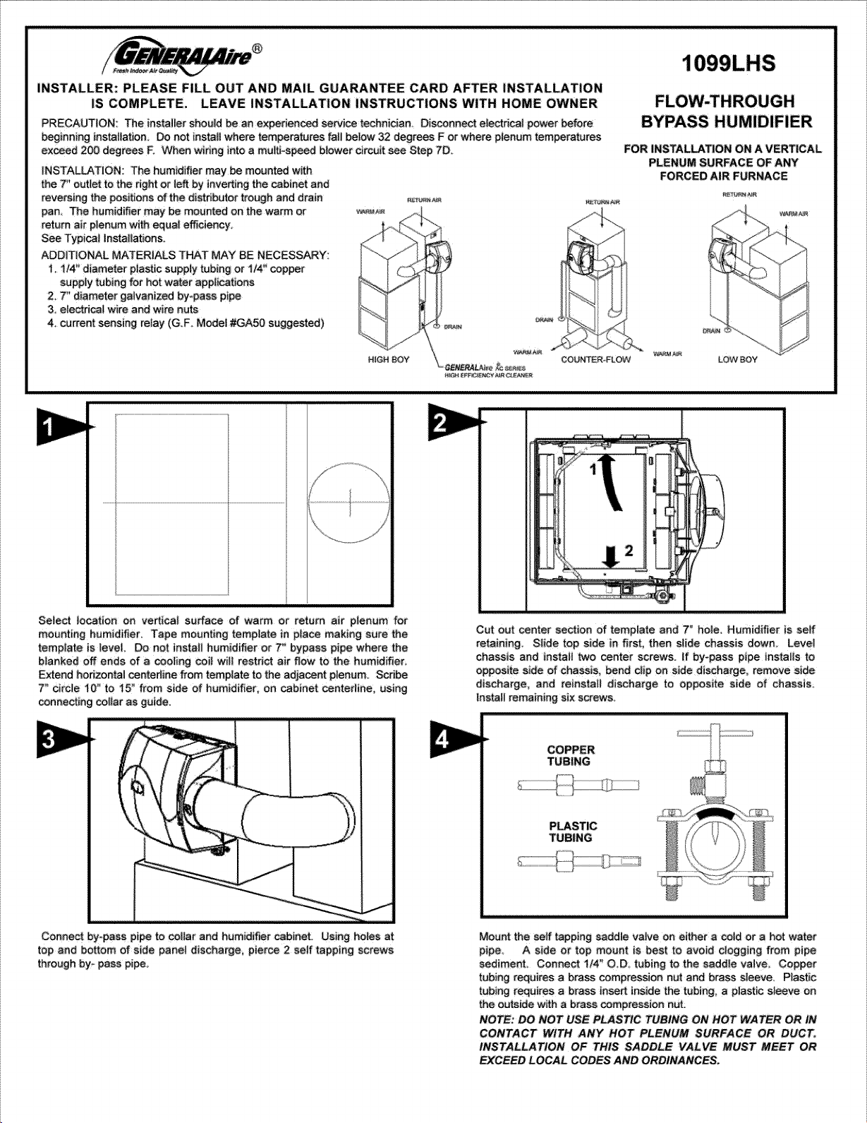
1. Select location on vertical surface of warm or return air
plenum for mounting humidier. Tape mounting template
in place making sure the template is level. Do not install
humidier or 7" bypass pipe where the blanked off ends of
a cooling coil will restrict air ow to the humidier. Extend
horizontal centerline from template to the adjacent plenum.
Scribe 7” circle 10” to 15” from side of humidier, on cabinet
centerline, using connecting collar as guide.
2. Cut out center section of template and 7” hole. Humidier
is self retaining. Slide top side in rst, then slide chassis
down. Level chassis and install two center screws. If bypass
pipe installs to opposite side of chassis, bend clip on side
discharge, remove side discharge, and reinstall discharge to
opposite side of chassis. Install remaining six screws. Insert
Vapor Pad
®
assembly, with black patch of Vapor Pad
®
on top.
3. Connect by-pass pipe to collar and humidier cabinet. Using
holes at top and bottom of side panel discharge, pierce 2 self
tapping screws through the bypass pipe.
1
2
Last Updated: 0
2-2022
Our Brands
®
400 Midwest Rd.
T
oronto, ON M1P 3A9
Canada
Toll Free: (888) 216-9184
www.
generalaireiaq.ca
sales@generalaire
iaq.ca
Model 1099LHS Humidier Installation Manual
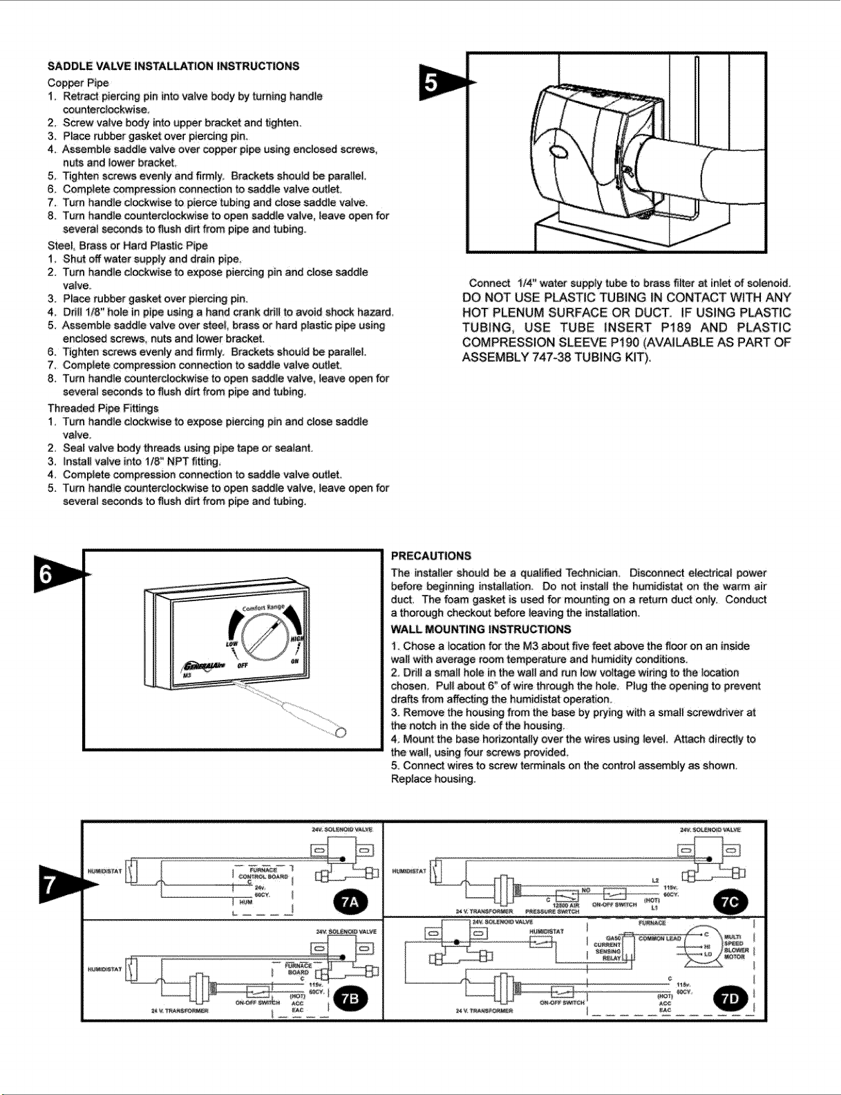
6.
Connect 1/4" water supply tube to brass filter at inlet of
solenoid.
CAUTION: Do not use plastic tubing in contact with any hot
plenum surface or duct. If using plastic tubing, use tube
insert GP-81:29
and plastic compression sleeve GP-P190
(available as part of assembly
GP-747-38 tubing kit.
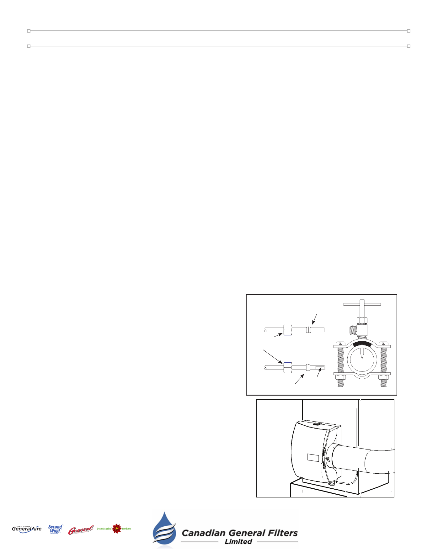
Saddle Valve Installation
!
4. Mount the Self-Tapping Saddle Valve.
5. Install the copper or plastic tubing.
Connect 1/4” O.D. tubing to the saddle valve. Copper
tubing requires a brass compression nut and brass sleeve.
Plastic tubing requires a brass insert inside the tubing, a
plastic sleeve on the outside with a brass compression nut.
See gure to right.
Copper Pipe:
1. Retract piercing pin into valve body by turning handle counterclockwise.
2. Screw valve body into upper bracket and tighten.
3. Place rubber gasket over piercing pin.
4. Assemble saddle valve over copper pipe using enclosed screws, nuts and lower bracket.
5. Tighten screws evenly and firmly. Brackets should be parallel.
6. Complete compression connection to saddle valve outlet.
7. Turn handle clockwise to pierce tubing and close saddle valve.
8. Turn handle counterclockwise to open saddle valve, leave open for several seconds to flush dirt from pipe and tubing.
Steel, Brass or Hard Plastic Pipe:
1. Shut off water supply and drain pipe.
2. Turn handle clockwise to expose piercing pin and close saddle valve.
3. Place rubber gasket over piercing pin.
4. Drill 1/8" hole in pipe using a hand crank drill to avoid shock hazard.
5. Assemble saddle valve over steel, brass or hard plastic pipe using enclosed screws, nuts and lower bracket.
6. Tighten screws evenly and firmly. Brackets should be parallel.
7. Complete compression connection to saddle valve outlet.
8. Turn handle counterclockwise to open saddle valve, leave open for several seconds to flush dirt from pipe and tubing.
Threaded Pipe Fittings:
1. Turn handle clockwise to expose piercing pin and close saddle valve.
2. Seal valve body threads using pipe tape or sealant.
3. Install valve into 1/8" NPT fitting.
4. Complete compression connection to saddle valve outlet.
5. Turn handle counterclockwise to open saddle valve, leave open for several seconds to flush dirt from pipe and tubing.
CAUTION: Turn off water supply.
CAUTION: Do not use plastic tubing on hot water or in contact with any hot plenum surface or duct.
Installation of this saddle valve must meet or exceed local codes and ordinances.
!
!
COPPER
TUBING
PLASTIC
TUBING
Plastic
Sleeve
Brass
Insert
Brass
Sleeve
Compression
Nut
Last Updated: 0
2-2022
Our Brands
®
400 Midwest Rd.
T
oronto, ON M1P 3A9
Canada
Toll Free: (888) 216-9184
www.
generalaireiaq.ca
sales@generalaire
iaq.ca
Model 1099LHS Humidier Installation Manual
!
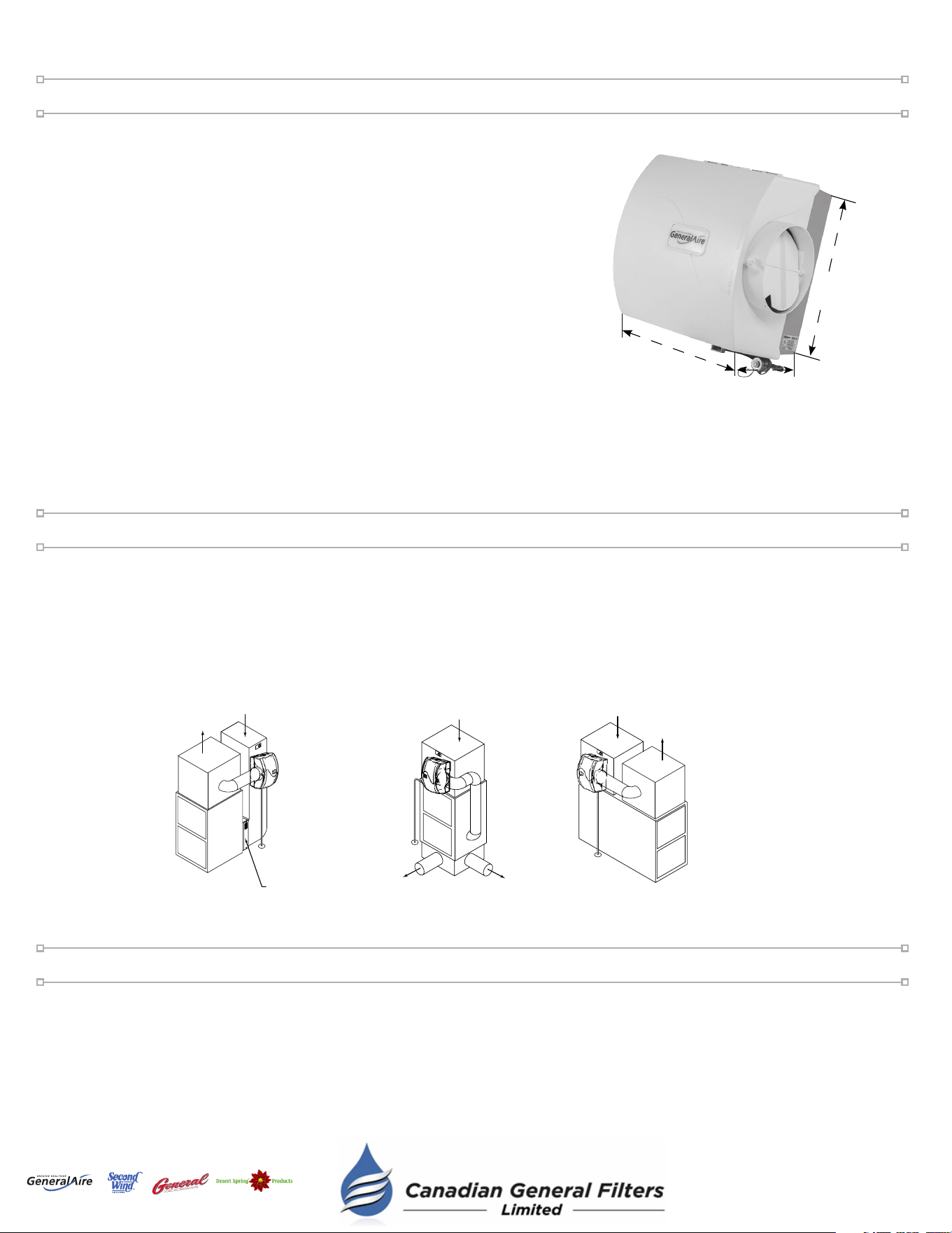
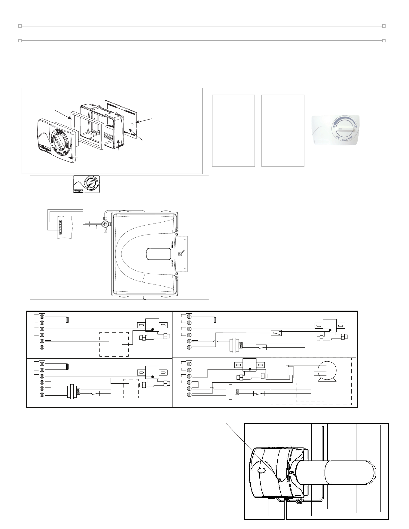
Installing / Wiring the Control
7D
7. Connect drain hose to 1/2" spout on humidier cabinet using hose
clamp if necessary. Run 1/2" hose to suitable drain such as oor
drain, sewer or laundry sink.
CAUTION: Be sure hose has continuous slope and is not kinked at
any point.
8. Turn on water supply and check operation of humidier. Set humidistat
to a demand setting. With the furnace off, the solenoid valve should
be closed. Start the furnace, the solenoid valve should open when
the blower or burner circuit is energized. Check ow of water through
distributor trough and evaporator pad. The standard Orange orifice
GF-
GA4299 will supply approximately 4.75 GPH of water at
a line water pressure of 60 psi. For low water pressures (20-40 psi) a
larger Blue orifice
GF-
GA4232 is available to provide the same
flow.
Leave humidistat set at the recommended setting.
WIRE JUMPER
7D
(HOT)
115v.
60CY.
ON-OFF SWITCH
COMMON LEAD
FURNACE
C
HI
LO
GA50
CURRENT
SENSING
RELAY
MULTI
SPEED
BLOWER
MOTOR
AC L
AC N
HUM
SNSR
24V. SOLENOID VALVE
727-58 24 V. TRANSFORMER
(HOT)
C
115v.
60CY.
ON-OFF SWITCH
AC L
AC N
HUM
SNSR
24V. SOLENOID VALVE
727-58 24 V. TRANSFORMER
L1
C
NO
(HOT)
L2
115v.
60CY.
ON-OFF SWITCH
12500 AIR
PRESSURE SWITCH
AC L
AC N
HUM
24V. SOLENOID VALVE
727-58 24 V. TRANSFORMER
R
FURNACE
CONTROL BOARD
C
24v.
60CY.
AC L
AC N
HUM
SNSR
FURNACE
BOARD
W
WIRE JUMPER
OUTDOOR TEMP. SENSOR
OUTDOOR TEMP. SENSOR
OUTDOOR TEMP. SENSOR
OUTDOOR TEMP. SENSOR
N
W
24v.
60CY.
WIRE
JUMPER
WIRE
JUMPER
WIRE
JUMPER
6A6A 6B
6C
6.
GF-MHX3: DUCT Mounting (Return Air Duct) / WALL Mounting
6D
!
WARNING: ALL WIRING SHOULD COMPLY WITH LOCAL ELECTRICAL CODES.
*Complete installation instructions for the (manual or automatic) humidistat can be found inside the humidistat box.
Thin Outer
Gasket Frame
Thick Gasket
Frame
Mounting Base
1
Face
2
3
4
5
Gasket W
Thin Inner
all
DUCT MOUNT
Use Parts:
1
2
3
4
WALL MOUNT
Use Parts:
1
3
4
5
MHX3C Humidistat Installation
C
G
R
W
Y
BLUE 24V SOLENOID
VALVE WIRES
24VAC FROM FURNACE
24V From
CIRCUIT BOARD
GENERALAIRE HUMIDISTAT
GeneralAire
®
Humidifier
GeneralAire
®
Humidistat
Furnace
Circuit Board
Blue 24V
Solenoid
Valve Wires
USING GF-X3 DIGITAL HUMIDISTAT
Model 1099LHS Humidier Installation Manual
• The operating principle of the humidier is based on the most efcient and economical means of evaporating
water to the air. The humidier uses only 2.5 watts of electrical power during operation, less than the
smallest household light bulb. The heat necessary for evaporating water is produced by the furnace. The
water supply to the humidier is controlled by the electric solenoid valve. The humidistat connected in series
with the solenoid provides low voltage control of the humidier. The humidistat is designed for wall mounting
in the living area or surface mounting on the return air duct.
• Water ows through a strainer, is metered through an orice to provide the proper amount of water, and is
supplied to the Vapor Pad
®
by the distributor trough. Approximately
200 CFM of air is by-passed from the warm air plenum through the
humidier and returned to the cold air plenum. Moisture is evaporated
to the air passing through the Vapor Pad
®
.
• Minerals are not blown into the air stream as occurs in atomizing
humidiers; they are left on the Vapor Pad
®
where a high percentage is
carried off with the waste water.
• When the humidier is installed and operating, no adjustments are
necessary other than setting the control knob on the humidistat to
the desired level of humidication. Set knob on the humidier to
"HI" or "WINTER" position. To turn the humidier off, close the water
supply valve, switch electrical power off and turn the humidistat off.
If furnace is used for summer cooling or ventilating set air damper on
"LOW" or "SUMMER".
• CAUTION: Do not set relative humidity too high during cold weather. Excessive humidity may cause
condensation on windows or in walls. Refer to recommended settings as described in the humidistat owners
manual.
How the Humidifier Works
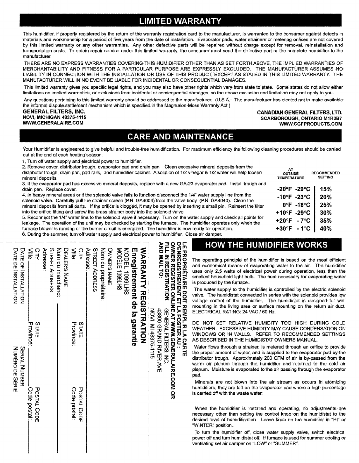
At Outside
Temperature
Recommended
Setting
-20°F -29°C 15%
-10°F -23°C 20%
0°F -18°F 25%
+10°F -12°C 30%
+20°F -7°C 35%
+30°F -1°C 40%
!
Maintenance
Your Humidier is engineered to give helpful and trouble-free humidication. For maximum efciency the following
cleaning procedures should be carried out at the end of each heating season:
1. Turn off water supply and electrical power to humidifier.
2. Remove cover, water distributor trough, Vapor Pad
®
, pad rails and drain pan. Clean excessive mineral deposits
from the distributor trough, drain pan, pad rails and humidifier cabinet. A solution of 1/2 vinegar & 1/2 water will
help loosen mineral deposits. Inspect drain hose, clean or replace as necessary.
3. Insert a new GF-GA23 Vapor Pad
®
(black notch on top). Install trough, pad rails and drain pan. Replace cover,
reconnect electrical plug. Replace Vapor Pad
®
yearly for peak performance.
4. In heavy mineral areas, or if the solenoid valve fails to function, disconnect the 1/4” water supply line from the
solenoid valve. Carefully pull the strainer screen from the valve body. Clean the mineral deposits from all parts.
If the orifice is clogged, it may be opened by inserting a small pin. Reinsert the filter into the valve body
.
5. Reconnect the 1/4” water line to the solenoid valve if necessary. Turn on the water supply and check all points
for leakage. The operation of the unit may be checked by starting the furnace. The humidifier operates only
when the furnace blower is running or the burner circuit is energized. The humidifier is now ready for operation.
6. During the summer, turn off water supply and electrical power to humidifier.
Last Updated: 0
2-2022
Our Brands
®
400 Midwest Rd.
T
oronto, ON M1P 3A9
Canada
Toll Free: (888) 216-9184
www.
generalaireiaq.ca
sales@generalaire
iaq.ca
Model 1099LHS Humidier Installation Manual
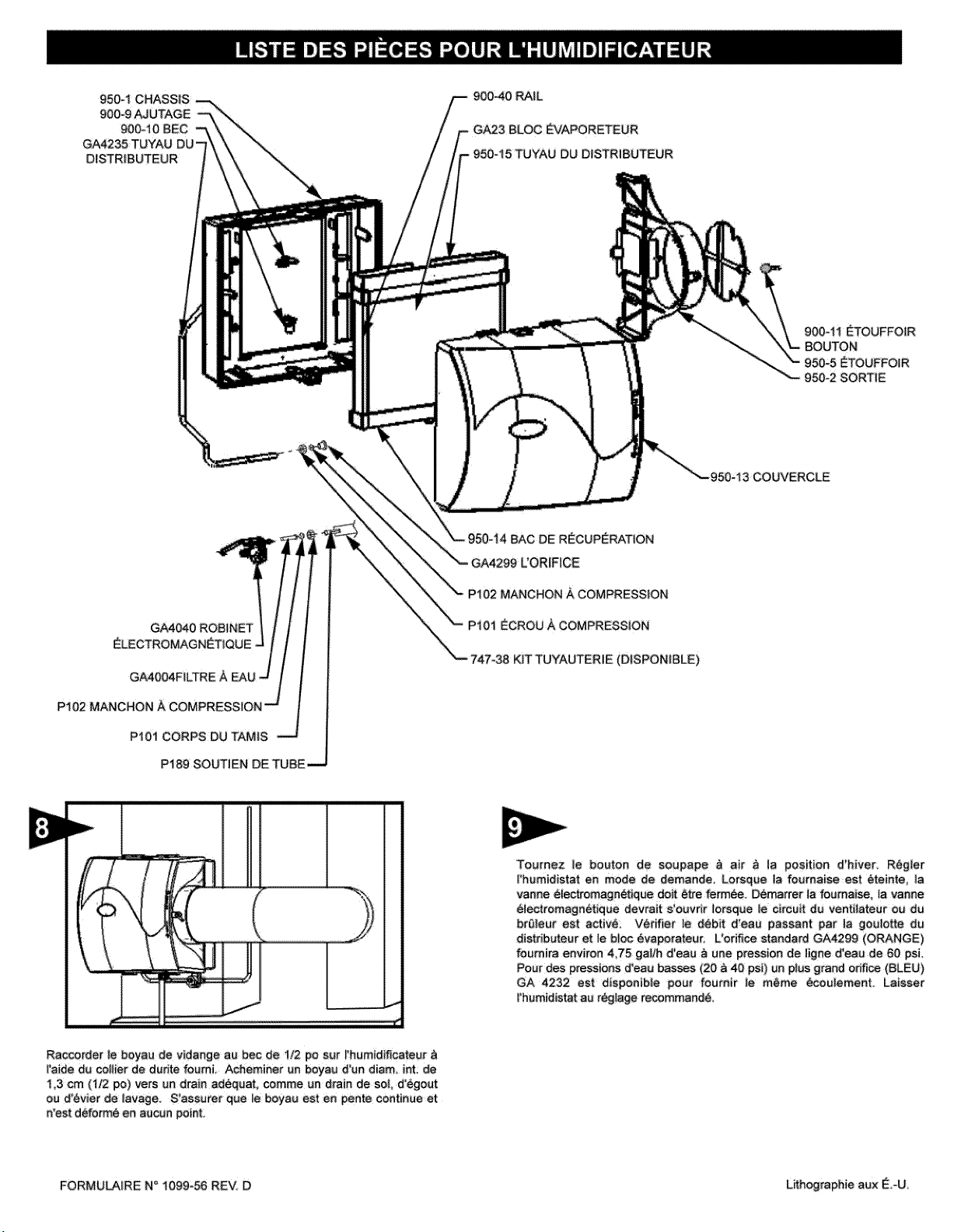
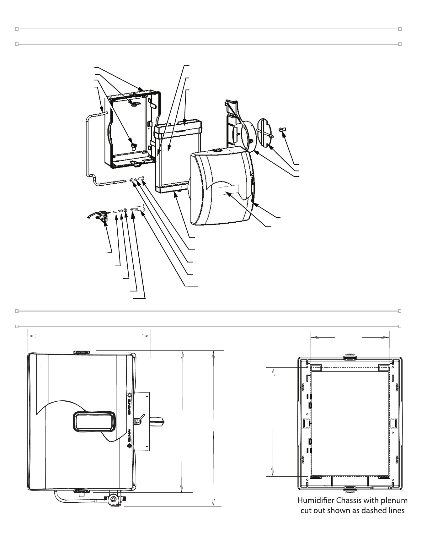
Humidifier Chassis Duct Cut Out
GF-950-14 DRAIN PAN
GF-900-11 DAMPER KNOB
GF-950-5 DAMPER DISK
GF-950-2 SIDE PANEL
DISCHARGE
GF-900-40 PAD RAIL
GA-23 EVAPORATOR PAD
GF-950-15 DISTRIBUTOR TROUGH
GF-950-13 COVER
GF-950-1 CHASSIS
GF-GA4040 SOLENOID VALVE ASM
GF-GA4004 STAINER SCREEN
GF-P102 COMPRESSION SLEEVE
GF-900-9 NOZZLE
GF-900-10 SPOUT
GF-GA4235 DISTRIBUTOR TUBE
GP-81-35 COMPRESSION NUT
GP-81-29 BRASS TUBE INSERT
GP-81-60 TUBING KIT (AVAILABLE)
GF-900-16 NAMEPLATE
15 1/2”
17 1/2”
13”
12”
8-7/8”
Parts Drawing
GF-GA4299 ORIFICE (Orange)
GF-P102 COMPRESSION SLEEVE (BRASS)/GP-81-30 COMPRESSION SLEEVE (PLASTIC)
GP-81-35 COMPRESSION NUT

Model 1099LHS Humidier Installation Manual
Troubleshooting
1. My humidifier continues to run.
Check for the following:
• The valve might be stuck in the "open" position.
• Check for wiring errors.
• Is the unit sized properly for your home? If it is rated for a smaller-sized home than the home in which it is
installed, it will work "overtime" to reach the humidification levels desired.
• Check the Vapor Pad
®
. If it is clogged, the pad will reduce the humidifier efficiency. Replace if necessary.
2. My solenoid valve is making a "chatter" noise.
This can be caused by any of the following:
• The power to the valve is less than 18V AC.
• The solenoid is causing a "water hammer condition" thru the water pipes (valve closes quickly and shuts off
water flow, which in turn creates pressure behind the valve that has no avenue of relief). You may want to install
a water hammering device with your plumbing, or contact your local plumber to determine the best solution.
• The humidistat is located too close to the humidifier or the by-pass pipe. Your humidistat should be a min. of
1.5' away or greater.
• The humidistat could have a buildup of dust, causing a faulty reading.
• The solenoid valve might be dirty. Remove, inspect and clean if necessary.
• Water supply pressure going to the valve may be too low.
• The hold down nut on top of the solenoid, as it may be loose.
3. The humidifier is not raising the humidity levels in my home.
Check for the following:
• Ensure you have changed / replaced your Vapor Pad
®
at the proper intervals (once per year) to ensure the
greatest production of moisture.
• Check the setting of your humidistat to ensure it is set higher than current humidity levels in your home (when in
doubt, turn it all the way to the right at maximum production). If you don't know what your current humidity
level is, use an instrument called a thermohygrometer (Model GF-610 suggested) to measure both heat and
humidity levels in your home.
• Check to see that your humidifier model is designed to produce the amount of moisture (GPD) you need.
• Have you recently installed hardwood floors? Have you recently remodeled and added on to your home? These
can both increase your home's demand for humidity. Options include connecting your humidifier to the hot
water supply (which can increase output by as much as 30%), or installing a new humidifier model that can
generate more humidity
.
• The unit is not recommended for heat pumps or plenum temperatures < 120° F.
4. My humidifier will not turn on.
The following might be occurring:
• Check to see your humidifier is plugged in, that the breaker is engaged, and that power to other items from the
same source is working.
• Check the on/off switch to be sure it is in the O (Open / Summer) position.
• Ensure a fuse has not blown.
• Check that connectors are properly inserted in the terminal block.
• Make sure the furnace is operating in the heat mode.
To ensure your safety and the longevity of your unit, we recommend
contacting a licensed contractor to perform any repairs or maintenance.
!
Last Updated: 0
2-2022
Our Brands
®
400 Midwest Rd.
T
oronto, ON M1P 3A9
Canada
Toll Free: (888) 216-9184
www.
generalaireiaq.ca
sales@generalaire
iaq.ca

Model 1099LHS Humidier Installation Manual
1. How does a humidifier help with my allergies?
Dry air can lead to a host of problems for allergy and asthma sufferers. Dry climates, winter air, and articial
heat all contribute to the discomfort by drying out your skin, throat and delicate sinus passages and airways
(which can contribute to sinusitis). Winter is an especially bad time for dry air as home heating systems,
especially forced-air systems, reduce the amount of moisture in the air while humidity levels outdoors typically
dip as well.
2. What range of humidity is ideal?
Research shows that 40-60% relative humidity is ideal. Outside this range, your risk of being adversely affected
increases.
3. How often should I change my Vapor Pad
®
?
We recommend replacing your Vapor Pad
®
at least once per year. Minerals build up on the vapor pad over
time, which in turn:
• Reduces the pad's ability to absorb water.
• Prevents the warm air from owing through the pad (Warm air moving though the water-soaked pad
causes the water in the pad to evaporate. It is this process that delivers moisture throughout your home
via the home's duct system).
4. Can't I simply clean my Vapor Pad
®
instead of replacing it?
At the factory we put a coating on the Vapor Pad
®
that helps it absorb water and control water ow. This
coating is very efcient, however, it is also fragile. The coating is similar in composition to the minerals
that accumulate on the pad. If you subject the Vapor Pad
®
to cleaning, you usually remove much of the
coating and the pad becomes ineffective. This reduces the output of the humidier and increases water
consumption.
Instead we recommend the Vapor Pad
®
be replaced each year.
5. Why would I want to install a humidifier?
For many reasons:
1. Since the air in your home is always trying to reach its saturation point, it will absorb water wherever
it can; from the bodies of you and your children, your pets, your furniture and even your house plants.
As a result your skin, throat and nasal passages dry out, leaving you more susceptible to physical
discomfort, colds, u and even infection. Allergy and asthma sufferers can be especially affected by air
that's too dry.
2. Dry air causes dry, itchy skin.
3. Dry air cracks expensive woodwork, oors, musical instruments, artwork and furnishings.
4. Annoying static electricity (caused by dry air) can damage computers, VCR’s and other electronic
equipment, requiring expensive repair.
5. Dry air can cause harm to expensive musical instruments like pianos and violins.
6. Dry air causes gaps in window & door frames, letting cold outdoor air in; causing you to turn up the heat
and increasing your heating bills! Controlled humidity from a GeneralAire
®
Humidier allows you the
luxury of dialing the thermostat back & reducing annual heating bills. For example, 68° at 40% relative
humidity feels just as warm as 74° at 20% humidity. Setting your thermostat back by as little as three
degrees can reduce annual heating bills by as much as 5%.
FAQ’s
Last Updated: 0
2-2022
Our Brands
®
400 Midwest Rd.
T
oronto, ON M1P 3A9
Canada
Toll Free: (888) 216-9184
www.
generalaireiaq.ca
sales@generalaire
iaq.ca