Installation & User Manual
FORM NO. 5500-32; Rev. B
1 | P a g e
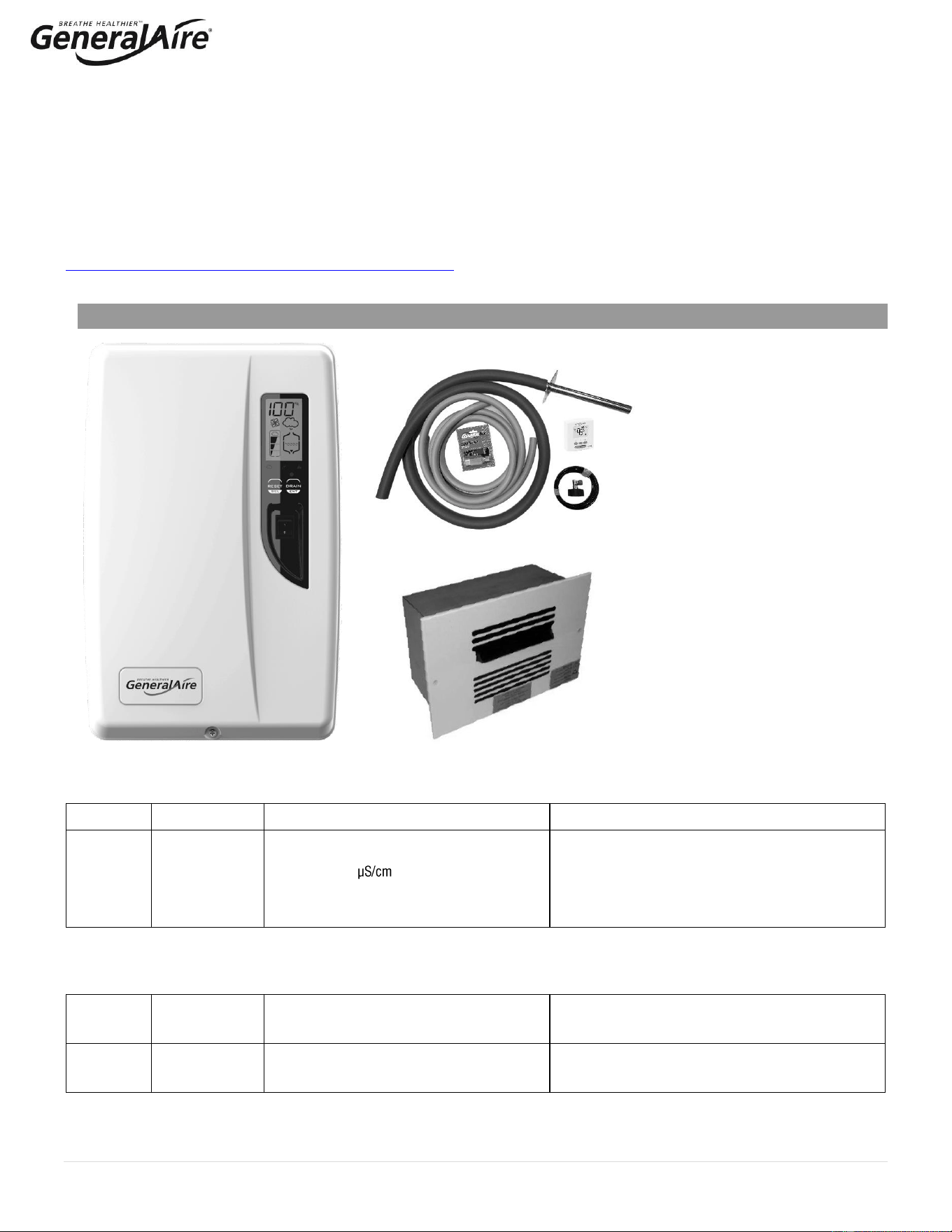
1. Duct Steam Humidifier
2. Installation Manual
3. Installation Kit
a. Steam manifold
b. 6’ Steam hose
c. 10’ drain hose
d. Water tube supply kit (10’ tubing)
e. Water fill connector
f. GFX4 Digital Automatic Humidistat
g. Ball valve
h. Hose clamps
i. Fasteners
j. Mounting straps
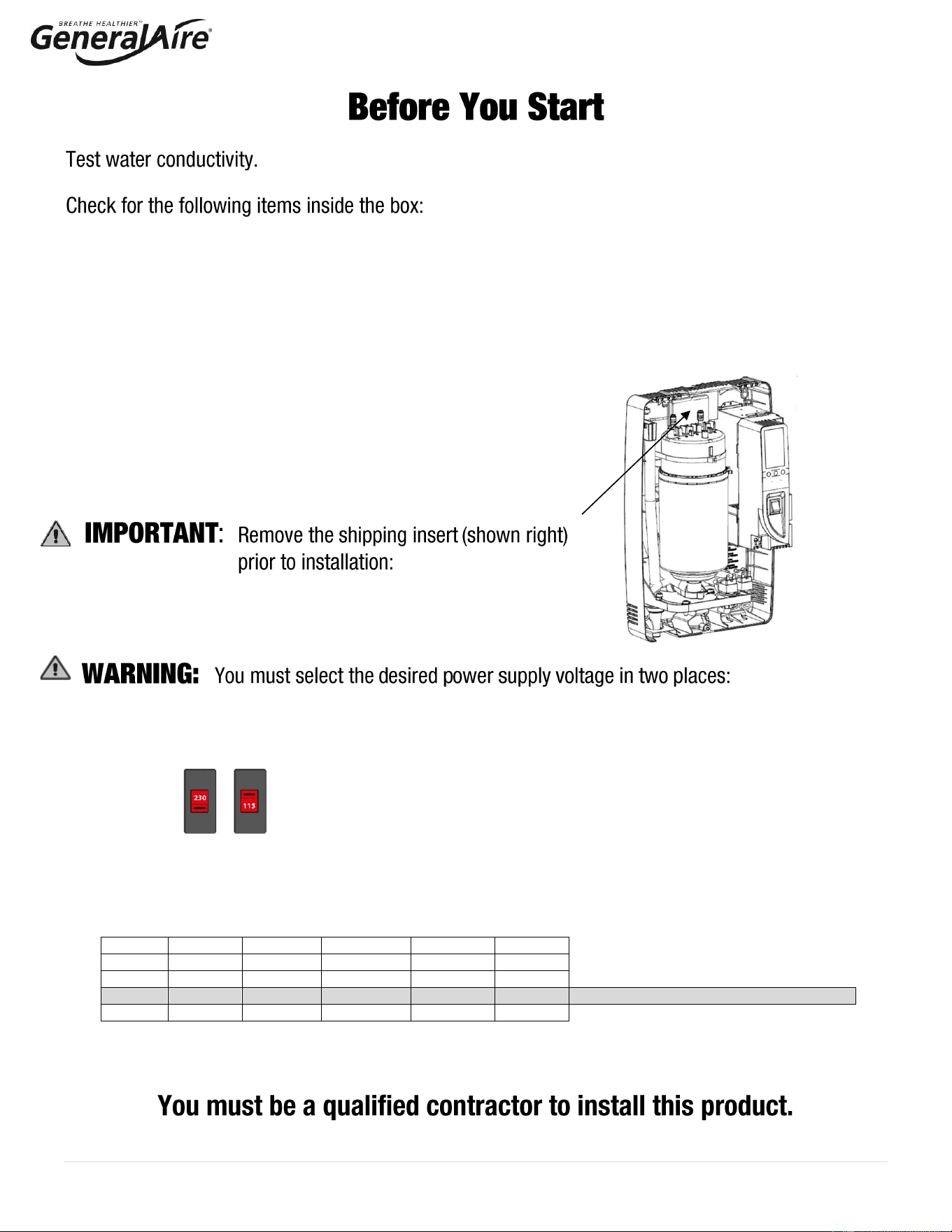
1. INTERNAL SWITCH: The humidifier can be powered at either a nominal voltage of 115 VAC 50/60 Hertz or a
nominal voltage of 230 VAC 50/60 Hz. THE FACTORY DEFAULT SETTING IS 230 VAC. If the main power supply
is 115 VAC, the setting must be changed accordingly, following the procedure described on page 14 of this
manual.
2. CONTROL PANEL - ON INITIAL STARTUP: Press the ‘RESET/SEL’ button and then adjust the value on the
display. Choose the desired value from one of the four options shown below and press the ‘DRAIN/ENT’ button to
confirm.
Option
Voltage
Current
Output
Output
Output
1
115 V
11 A
10.1 gpd
1.6 kg/h
3.5 lb/hr
2
115 V
14.5 A
13.9 gpd
2.2 kg/h
4.9 lb/hr
3
230 V
11 A
20.9 gpd
3.3 kg/h
7.3 lb/hr
Default setting if no selection is made
4
230 V
14.5 A
28.5 gpd
4.5 kg/h
9.9 lb/hr
2 | P a g e
Before installing or handling the humidifier please carefully read and follow the instructions and safety
standards described in this manual and on the labels attached to the 5500 Steam Humidifier. Test
water conductivity prior installation to ensure conductivity falls between 125 to 1250 μS/cm.
: DISCONNECT THE MAIN POWER BEFORE OPENING OR SERVICING THE HUMIDIFIER!
: ELECTRIC SHOCK HAZARD! The humidifier has components that are under power!
: SCALDING HAZARD! The humidifier has hot components (212°F / 100°C).
: Your humidifier requires water to operate. DO NOT mount it above materials or machinery that
could be damaged if a leak occurs. General Filters, Inc. assumes no responsibility for consequential or
inconsequential damage as a result of any leaks.
: DO NOT introduce steam into duct that has interior insulation.
:
• Install the humidifier out of the reach of children.
• The humidifier must be installed in accordance with all local and national standards.
• All service and/or maintenance operations must be performed by qualified personnel who are aware of the
necessary precautions and are capable of performing the operations correctly.
• The conditions of the environment and the power supply voltage must comply with the specified values listed
on the data label in the humidifier.
• All other uses and modifications made to the humidifier that are not authorized by the manufacturer are
considered incorrect, and the manufacturer assumes no liability for the consequences of any such unauthorized
use.
: Before Beginning Installation:
• Open cartons and check for damage. Do not install if damage is found.
• Check packing slip to ensure all items have been received. Notify General Filters, Inc. of any shortages or
damaged parts.
You must notify General Filters, Inc. within 5 working days of any damages or shortages.
: Disposal of the parts of the humidifier:
• The humidifier is made up of metallic and plastic parts.
• All parts must be disposed of according to the local standards on waste disposal.

3 | P a g e
TABLE OF CONTENTS
1. How The 5500 Steam Humidifier Works 4
1.1 Basic Operation 4
1.2 Cylinder Life 5
1.3 Calculating Humidity Load 5
2. Model Information 6
3. Installation 7
3.1 Positioning 7
3.2 Mounting / Unit Dimensions 7
3.3 Plumbing 9
3.4 Steam Distribution and Installation 10
3.5 Power Supply Voltage Selection 14
3.6 Power Wiring 14
3.7 Control Wiring 15
3.8 Wiring Connections 17
4. Start-Up 18
4.1 Startup Checklist 18
4.2 Starting the 5500 Humidifier Steam 18
4.3 Steam Humidifier Controller 18
4.4 Initial Configuration of the Steam Humidifier 18
4.5 Starting with a New Steam System or Replacement Humidifier 19
5. Operating The 5500 Steam Humidifier 19
5.1 Displaying Information 19
5.2 Selecting Signal Type 19
5.3 Changing The Maximum Production 20
5.4 Activating Manual Drain 20
5.5 Resetting The Hour Counter With New Cylinder Replacement 20
5.6 Using The GFX4 Humidistat 20
5.7 Alarms 21
6. Trouble Shooting 22
7. MAINTENANCE 23
7.1 Periodic Checks 23
7.2 Cylinder Maintenance 23
7.3 Replacement Parts 24
8. Technical Specifications 25
9. Limited Warranty 26
4 | P a g e
1. HOW THE 5500 STEAM HUMIDIFIER WORKS
1.1 Basic Operation
The 5500 Steam Humidifier is an electrode humidifier. Unlike heating elements,
electrode steam humidifiers produce steam for humidification by passing electric
current through the water between metal electrodes inside the plastic steam
generator cylinder. Steam output is directly proportional to the conductivity of the
water, the power supply (115V or 230V), and the amount of electrode immersed in
the water. Test the water prior to installation with a conductivity tester (use GFI #5539
or CGF #GF-AP-2 or similar) to ensure water conductivity falls between 125 to 1250
μS/cm.
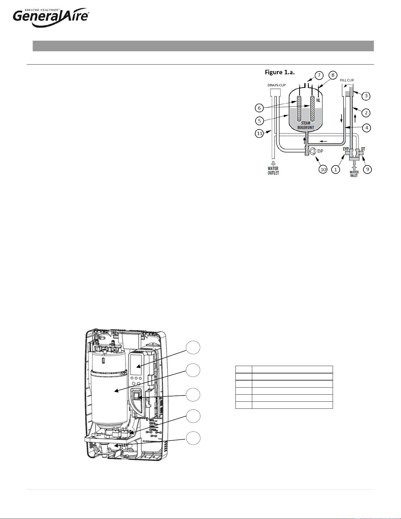
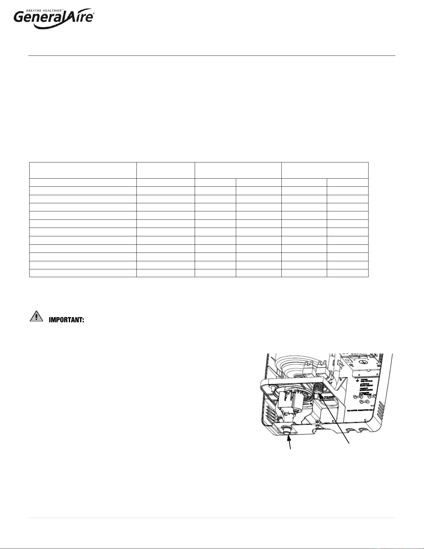
On a call for humidity, the 5500 Steam Humidifier (See Figure 1.a.) controller will
open the water fill valve (1) and allow water to enter the cylinder. A flow restrictor
prevents the unit from filling too quickly or with too much pressure. The water flows
up the fill tube (2) and into the fill cup (3), which creates a 1” air gap to prevent
backflow of contaminated water into the feed lines, through the second fill tube (4)
and into the bottom of the steam cylinder (5). Any backflow or overflow of water
travels through the overflow hose (11) to the drain.
As the water fills the cylinder, it will reach the electrodes (6) and electrical current will begin to flow. As the water continues to fill the
cylinder, the current will increase. This is monitored by an amperage transformer connected to one of the power wires located on the
electronic controller. When the desired current is reached, the fill valve will close, and the water will then begin to warm and produce
steam. If the water reaches the cylinder full probe (8) or if current rises too much, the drain pump (10) will be activated to drain away
some water and reduce the current flow to acceptable levels. Note that any time the drain pump is activated, the tempering valve (9)
will be opened for tempering the hot drained water down to less than 140°F / 60°C in accordance to local and national standards.
Periodically, the unit will activate the drain pump (10) and drain water to reduce mineral concentration. Every 120 hours the unit
automatically drains to remove mineral sediment on the bottom of the cylinder. A strainer in the cylinder helps to prevent mineral debris
from jamming the drain pump.
If the 5500 Steam Humidifier remains powered but idle (i.e. without producing steam) for more than 72 hours (3 days), the cylinder
will automatically be emptied of water and will not refill until the unit is restarted. If there is no water in the cylinder, there will be no
current flow and no steam production.
The electrodes do not burn out, but they will eventually become completely coated with minerals and the cylinder will then need to be
replaced. Cleaning cylinders may cause electrode damage, therefore voiding its warranty. See 7.2.2 maintenance section
on page 22.
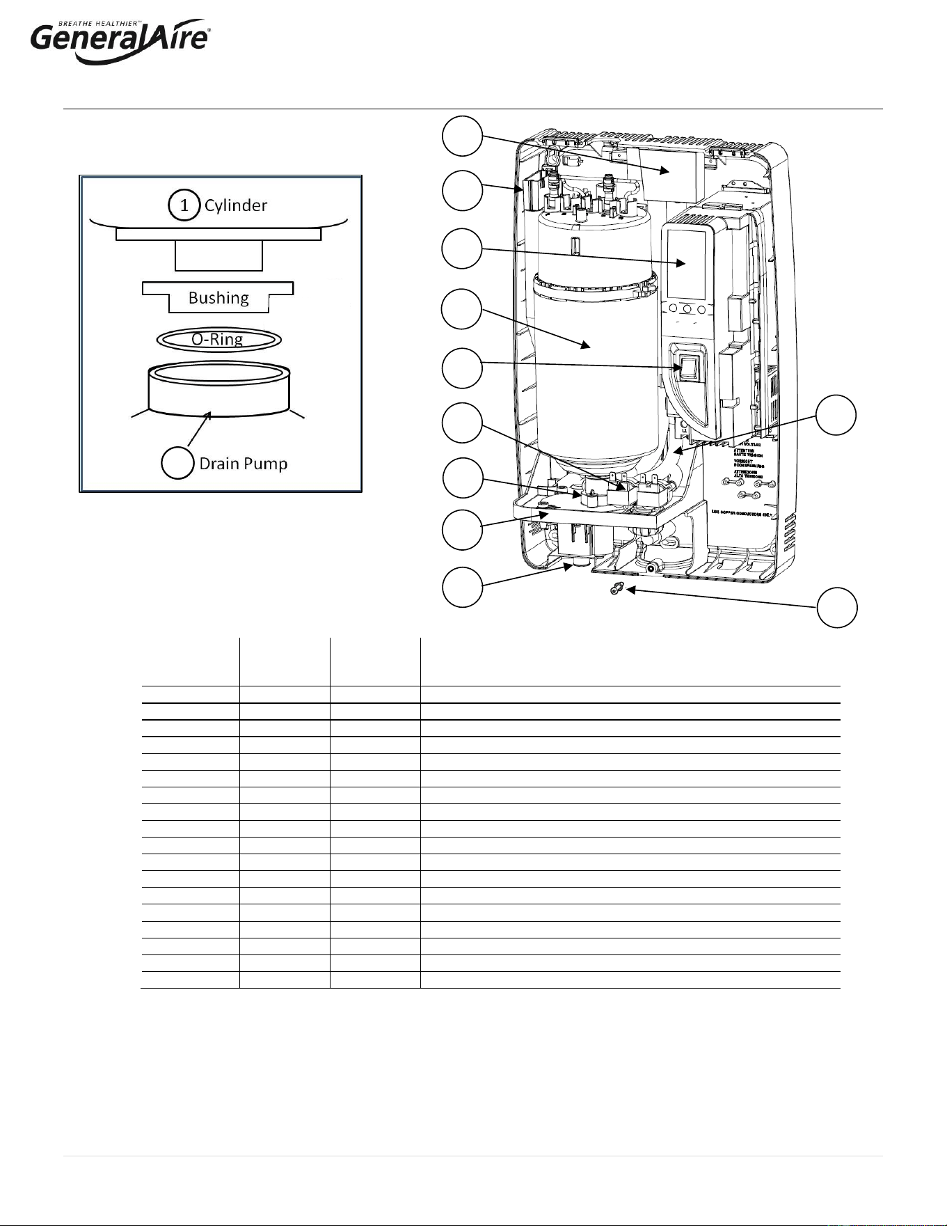
See Figure 1.b. for basic components.
No.
Description
A
User Interface / Display
B
Steam Generator Cylinder
C
ON / OFF Switch
D
Fill & Tempering Valves
E
Drain Pump
Key
Figure 1.b
F
A
F
B
F
C
F
D
F
E

5 | P a g e
1.2 Cylinder Life
1.2.1 Basics of the Steam Cylinder
The Steam Cylinder is the engine of the humidifier. As the water is evaporated inside the cylinder, minerals are left behind.
Much of these minerals are removed through the cylinder drain, however, some are deposited on the walls of the cylinder and
the cylinder electrodes. When a lower section of the electrodes develops a thick coating, the water level is raised to expose
clean electrode surface. Eventually minerals cover the electrodes’ entire length with a thick coating and little electrical current
can pass between them, resulting in poor steam output. The humidifier can sense the low amperage and will display the E8
Cylinder Expired error code. There are several factors that influence cylinder life.
1.2.2 Water
Water characteristics (mineral percentage and types) influence cylinder life and can vary greatly from place to place. Most
water conditions result in flaky scale that eventually fills the bottom of the cylinder until it can no longer function. Water with
high silica content can result in a thin glass-like coating on the electrodes that is highly insulating resulting in shorter cylinder
life. Use only cold water since the supply water is used to temper the hot drain water. Water quality affects the operation
of this unit, so the 5500 Steam Humidifier should be supplied with water that is untreated, drinkable, not softened, and not
demineralized. The water converted into steam is automatically replaced through an electric fill valve.
1.2.3 Water Filtration
Typically, additional filtration of the incoming water supply is not necessary. If mineral content is known to reduce cylinder life
excessively or if cylinder life proves insufficient, then water filtration can be added. In most cases the addition of a two-element
water filter can improve cylinder life. The filter should contain an activated carbon element and a particulate filter element rated
for about 5 microns or less (micron is a size measurement) with a flow rate of at least 2 GPM. The activated carbon will absorb
much of the mineral content while the particulate filter will catch any granular material or sediment. It is important to remember
that an increase in cylinder life will be accompanied by the need to replace filter elements with each cylinder change.
1.2.4 Humidity Load and Cylinder Life
Humidity load demands affect cylinder life. Normal installations where humidity capacity is properly sized require only
intermittent periods where full humidifier capacity is required. This allows the water level in the cylinder to be increased only as
electrode segments become insulated thus extending cylinder life.
Installations that require constant operation at full capacity will reduce cylinder life. The water level in the cylinder is, on
average, much higher and the electrodes become completely insulated more quickly.
The importance of providing adequate humidifier capacity should not be underestimated.
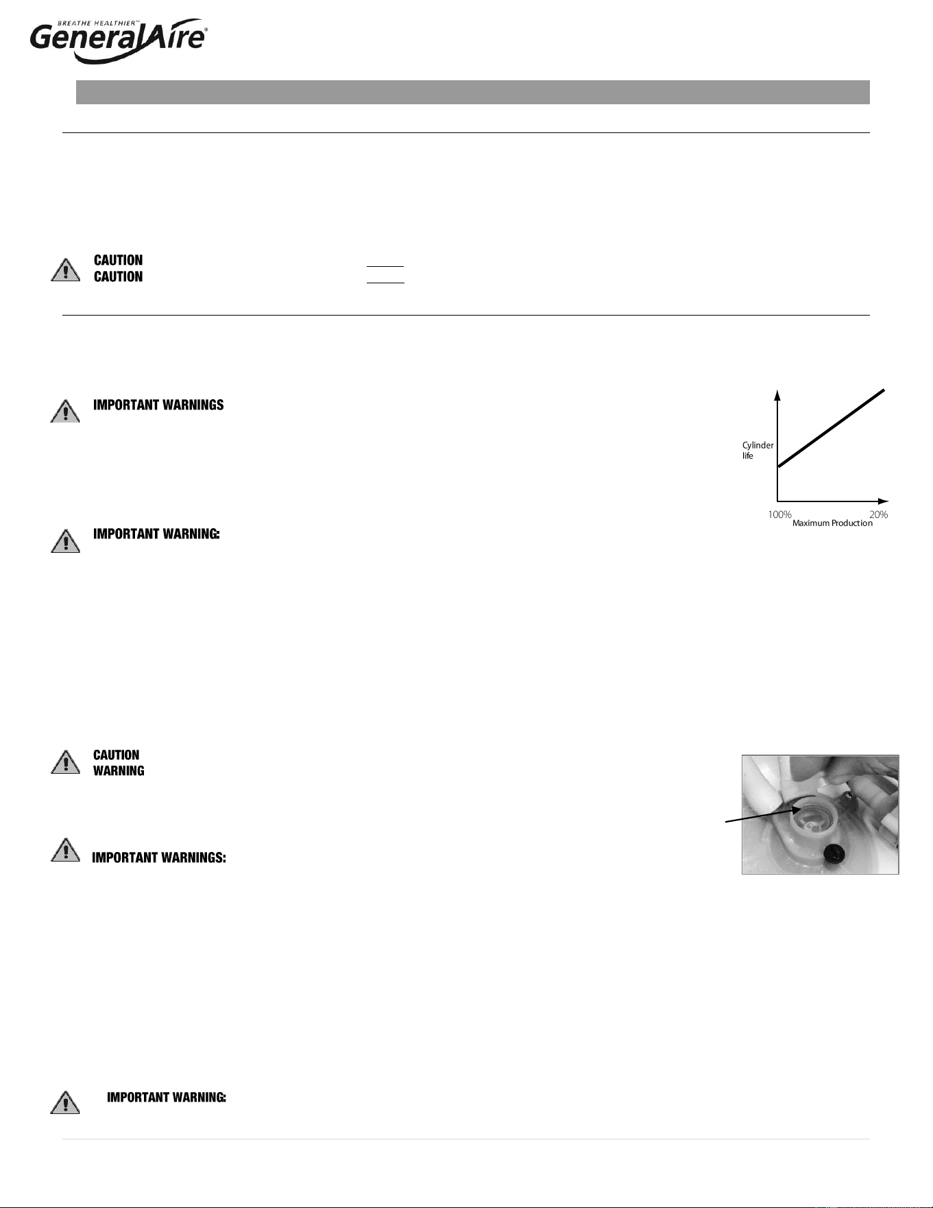
1.2.5 Maximum Production
Another factor affecting cylinder life is the maximum production setting. A higher production
rate will result in a shorter cylinder life (See Figure 1.c.).
1.2.6 Structures Under Construction
In high-end construction projects, humidification is often required while the structure is being finished. Humidification is
necessary to protect and stabilize wood floors, trim and decoration. Humidification load, however, in an unfinished structure
may be five to eight times higher than when finished. 5500 Steam humidifiers may be operated while construction is underway,
but reduced cylinder life is to be expected. Good practice dictates that the steam cylinder also be replaced once the
project is complete.
1.3 Calculating Humidity Load
1.3.1 Steps to Estimate Humidity Load
Humidity Load Calculation (GPD)
Total Square Footage
x Average Ceiling Height
x Factor (From Table 1.b.)
x 1.05 for each Fireplace
x 2.88 convert to gallons/day
= Gallons per Day
Table 1.b.
Pounds of Moisture / Hour / Cubic Foot *
Indoor Air
Temp °F/°C
35%
Indoor RH%
40%
45%
50%
68°F/20°C
0.00015
0.00018
0.00021
0.00024
70°F/21°C
0.00017
0.00020
0.00023
0.00026
72°F/22°C
0.00019
0.00022
0.00025
0.00028
* Based on .5 air charges per hour.
100
%
20%
Cylinder
Life
Figure 1.c
Output
6 | P a g e
1.3.1 Steps to Determine Humidity Load (cont.)
Example:
• 2,500 SF house with 1,000 SF basement (3,500 SF total square footage)
• 9 ft ceilings
• 70°F and 40% RH
• 2 fireplaces
• Humidity Load = 3,500 x 9 x .00020 x 1.05 x 1.05 X 2.88 = 20 GPD
For more accurate results based on U.S. geographic region, see the GeneralAire
®
on-line humidity calculator at
https://www.generalfilters.com/support/humidity-calculator.html.
2. MODEL INFORMATION
Model 5500
GFI #
CGF #
Description
Parts Included
5580
GF-5500
Model 5500 steam unit features:
115V – 230V dual voltage
125 – 1250 water conductivity
Duct steam injection
Drain pump
Output - 10 to 28.5 GPD (3.5 to 9.9 lb/hr)
Includes humidifier and duct steam mounting kit
components: 6 ft. steam hose, 8 inch steam
manifold, GFX4 humidistat, 10 ft. drain hose, ball
valve, water fill connector, water supply tubing kit,
mounting straps, hardware kit.
Optional Room Steam Kits (Purchased Separately)
7665
RMB15R
RMB15 – Room Steam Kit 115V. For use
with 115V setting on steam unit.
115V room blower assembly and grille package
7660
RMB35R
RMB35 – Room Steam Kit 230V. For use
with 230V setting on steam unit.
230V room blower assembly and grille package
Installation Kit
(Included)
RMB15 / RMB35
Room Steam Kits
(Optional; Sold Separately)
7 | P a g e
3. INSTALLATION
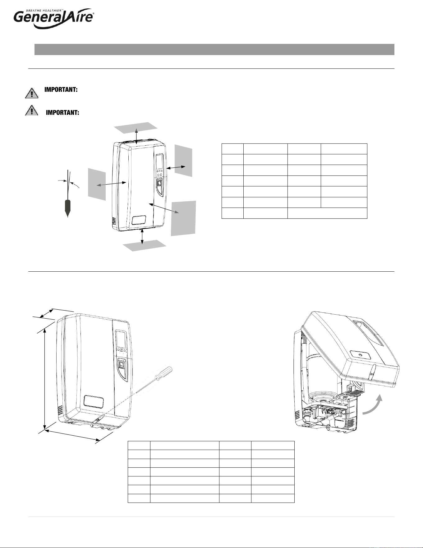
3.1 Positioning
The 5500 Steam Humidifier has been designed for wall mounting and since it is an electrode steam humidifier, should be
placed close to the point where the steam will be ducted to minimize the steam hose length (and the amount of condensate).
Certain minimum clearances must be maintained around the unit for safety and maintenance.
(See Figure 3.a. and Table 3.a)
DO NOT introduce steam into duct that has interior insulation.
3.2 Mounting / Unit Dimensions and Weight
3.2.1 Removing the Front Cover
The front cover is secured by two tabs at the top and one screw located at the bottom center of the unit. Use a Phillips head
screwdriver to remove the screw (Figure 3.b.), then swing and lift cover away from the back part of the unit (Figure 3.c.).
Return it in reverse order. Be careful not to over-tighten the screw. See Table 3.b. for dimensions.
Item
Description
Inches
Millimeters
A
Side
6
150
B
Top
6
150
C
Side
6
150
D
Bottom
6
150
E
Front
24
600
F
Angularity
0.2° max
Item
Description
Inches
Millimeters
A
Width
13.0
345
B
Depth
8.25
206
C
Height
21.0
533
Pounds
Kilos
Weight Empty
16
7.3
Weight with Water
24
10.9
Weight Shipping
26
11.8
Figure 3.a.
Figure 3.b.
Table 3.b.
A
E
B
D
C
F
Table 3.a.
C
B
A
Figure 3.c.
8 | P a g e
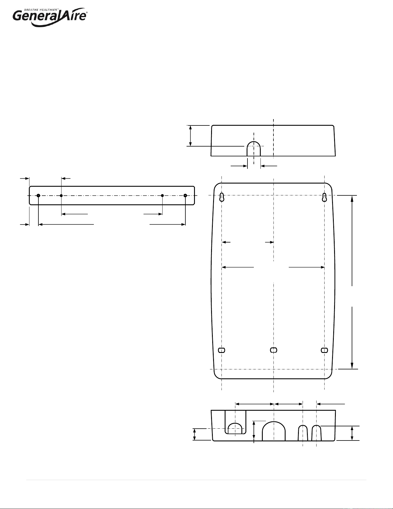
3.2.2 Fastening to the Wall
There are several options to install the steam unit to a finished wall or exposed studs.
• Option 1: Attach directly to a wall using the supplied screws and anchors. Use the two inner holes of the supplied
mounting strap as a template for the mounting holes (marked by “A” in Figure 3.d). Once marked, the two top screws
can be installed first and then the steam unit can be hung on the screws using the keyhole slots.
• Option 2: Attach to studs using the supplied mounting straps (Figure 3.e.). The mounting straps can be used to span
an a.) open stud cavity or b.) secured to studs through a finished wall. Secure the mounting straps to the studs using
the two outer holes. Then secure the steam humidifier to the mounting straps using the two inner holes, which will
align to the mounting holes in the steam unit.
TOP
Figure 3.d.
A
A
A
A
BOTTOM
3.15”
(80 mm)
1.38”
(35
mm)
2.13” (2.13
mm)
1.67”
(42.5
mm)
1.46”
(37 mm)
4.09”
(103.9 mm)
2.13”
(54 mm)
2.52”
(64 mm)
5.51”
(140 mm)
11.02”
(280 mm)
18.48”
(469.5 mm)
Figure 3.e
Mounting Strap
(2 per unit)
1”
(25.4 mm)
11.02” (280 mm)
16” (406.4 mm)
3.49”
(88.6 mm)
9 | P a g e
3.3 Plumbing
3.3.1 Water Characteristic Requirements
The humidifier must be supplied with water with the following characteristics:
• Incoming Pressure: Between 20psi and 90psi or 0.1 and 0.8 MPa (1 - 6 bar)
▪ Maximum intermittent pressure 110psi (8 bar)
• Maximum intermittent pressure includes water hammer or other supply water pressure spikes. High-water
pressure can be addressed with water hammer arrestors or pressure regulators.
• Temperature: Between 33°F and 70°F or 1°C and 21°C
• Flow-rate: Minimum of 0.45 L/min or 0.12gpm
• Hardness: No greater than 40°fH (equal to 400 ppm³ of CaCO)
• Conductivity: From 125 to 1250 μS/cm
• Absence of organic compounds
• The characteristics of the water of supply must fall within the following limits (Table 3.c.)
NORMAL WATER
LOW SALT CONTENT WATER
Units
Min
Max
Min
Max
Hydrogen ions (pH)
7
8.5
7
8.5
Specific conductivity (R,20°C)
μS/cm
125
500
100
350
Total dissolved solids (c R)
mg/l
(*)
(*)
(*)
(*)
Dry residue at 180°C
mg/l
(*)
(*)
(*)
(*)
Total hardness
mg/l CaC
³
O
0
200
50
160
Temporary hardness
mg/l CaC
³
O
=
150
=
200
Iron + Manganese
mg/l Fe + Mn
=
0.2
=
0.2
Chlorides
ppm Cl
=
20
=
30
Chlorides
mg/Si
2
O
=
20
=
20
Chlorine residue
mg/l Cl-
=
0.2
=
0.2
Calcium sulphate
mg/l CaS
4
O
=
60
=
100
(*) Values dependent on the specific conductivity: in general: cR~=0.65*σR, 20°C; R180~=0.9*σR, 20°C
Note: There is no relationship between the hardness and conductivity of water.
The following water types are not acceptable:
1. Softened water (will lead to foam, electrode corrosion and greatly shortened cylinder life)
2. Water containing disinfectants or corrosion inhibiters (potential irritants)
3. Industrial water, boiler water or water from cooling circuits
4. Any potentially chemically or bacteriologically-contaminated water
5. Heated water
3.3.2 Water Supply Connection
Connect the fill valve and the water supply line using a soft ¼” poly hose
capable of absorbing water hammering in order to avoid damage to the fill
valve. Route the water line through the bottom of the unit. As soft poly
tubing is used in the installation, install tubing support to prevent tubing
collapse and leaks. The fitting threads onto the fill valve inlet located on the
bottom of the humidifier using a 3/4” G connection (supplied). Note: A
strainer is built into the fill valve fitting underneath the unit that
requires periodic cleaning, be sure to allow clearance for access (See
Figure 3.f.).
3.3.3 Water Drain and Drain Hose
The 5500 Steam Humidifier requires a connection to a drain. A 10’ length of ¾” ID drain hose is included with unit. Attach
the drain hose to the water drain fitting and secure with the hose clamp provided. The hose must have a constant downward
slope and cannot be kinked, blocked, or create a trap, and can be routed directly to a floor drain, condensate pump, or drain
standpipe. Trim the drain hose as needed and ensure that that drain hose is located such that it cannot be blocked or
pinched after installation. See Technical Specifications for drain flow rate.
Fill valve and filter
Water drain fitting
Figure 3.f
Table 3.c.
10 | P a g e
3.3.4 Condensate Pump
When using a Condensate Pump, ensure pump is capable of storing about 1.1 gallons in 15 seconds with a pump output of 3
gpm or more.
3.4 Steam Distribution & Installation
The maximum allowed duct static pressure is 2 in. WC.
IMPORTANT: Allow 5 feet (1-1/2 M) of straight return duct downstream of the distributor pipe or nozzle for absorption of the
steam. Always allow 3 feet (0.9M) of straight supply duct upstream of the distributor pipe or nozzle for evaporation of the
steam. Turbulent air flow may require longer lengths
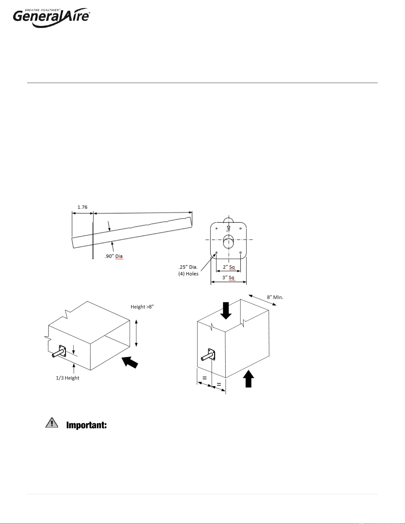
3.4.1 8” Steam Manifold (included)
The Model 5500 Steam Humidifier comes standard with an 8” steam manifold. The optional steam nozzle and steam
manifolds are available separately for other installations.
The 8” steam manifold should be installed on a vertical surface and must be angled up (see Figure 3.g.). The steam
distribution holes must always be facing up; the holes should never be installed facing downward. A condensate hose is not
required. To install the 8” steam manifold, drill a 1” diameter hole in the vertical surface of the duct as shown in Figure 3.h.
Apply silicone sealant to the mounting plate of the tube. Attach the manifold to the duct using (4) #10 sheet metal screws
(supplied). Connect the steam hose with the hose clamps provided.
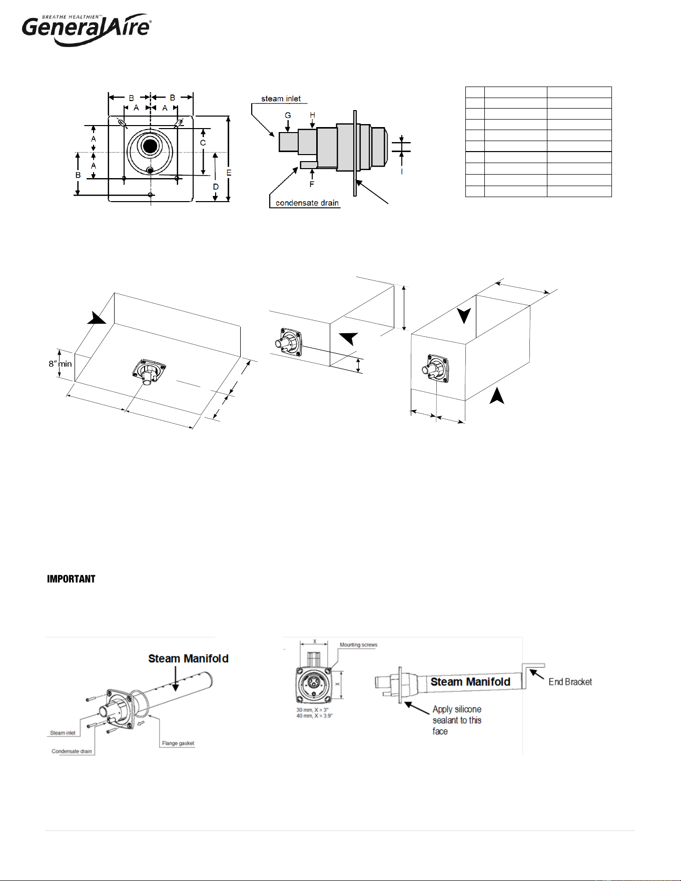
3.4.2 Steam Nozzle (optional)
The optional steam nozzle (See Figure 3.i. and Table 3.d.) can be used for horizontal surface installations (i.e., the bottom of a
horizontal duct) or vertical surface installations (See Figure 3.j.). A condensate hose is required. To install the steam nozzle, cut a 2-
1/2” round hole in the duct. Apply silicone sealant to the mounting plate and insert the nozzle through the hole and secure with sheet
metal screws. Connect the steam and condensate hoses using the hose clamps supplied. Select an accessible location on the duct,
allowing at least 36” of straight duct (no elbows or obstructions) after the point where the steam nozzle will be installed and the
clearances can be maintained as per the following drawings.
Fig. 3.g.
8” Steam Manifold
Fig. 3.h.
Installation of 8”
Steam Manifold on
Vertical Duct Surface
DO NOT introduce steam into a duct that has interior insulation.
Side Installation
Horizontal Duct
Side Installation
Vertical Duct
8.0
11 | P a g e
3.4.3 Steam Manifold (12” & 17.5” Options Available)
For certain applications a longer steam manifold may be required. Select an accessible location on the duct, allowing at least 36”
of straight duct (no elbows or obstructions) after the point where the steam manifold will be installed and the clearances can be
maintained as per the following drawings. To mount the steam manifold, cut or drill a 2-1/2” hole in the duct (See Figure 3.j.).
Apply caulk to the mounting plate of the manifold. Attach the steam manifold to the duct using (4) #10 sheet metal screws
(supplied). Install end bracket to maintain correct slope.
: Allow 5 feet (1-1/2 M) of straight return duct downstream of the distributor pipe or nozzle for absorption of the steam.
Always allow 3 feet (0.9M) of straight supply duct upstream of the distributor pipe or nozzle for evaporation of the steam. Turbulent
air flow may require longer lengths.
Optional stainless-steel steam manifold
USA: 25-10 12” or 25-11 17.5” Canada: GF-DPO30 Kit 12” or GF-DPO45 Kit 17.5”
Inches
Millimeters
A
1.24”
31.5 mm
B
1.96”
50 mm
C
2.20”
56 mm
D
2.26”
57.5 mm
E
3.93”
100 mm
F
0.31”
8 mm
G
0.86”
22 mm
H
1.18”
30 mm
I
0.47 or 0.87”
12 or 22 mm
Table 3.d.
Figure 3.i. Steam Nozzle
Airflow 1000 cfm min.
Airflow
Min 8”
Height >8”
=
=
Airflow
1000 cfm min.
1/3 Height
Airflow
1000 cfm min.
=
=
24” min
Upstream
36”min
Downstream
Figure 3.j.
Steam Nozzle Installation
Bottom Installation
Horizontal Duct
Side Installation
Horizontal Duct
Side Installation
Vertical Duct
Figure 3.k
Apply silicone
sealant to this
face
12 | P a g e
3.4.3 Cont. Return Condensate Connection (for Steam Nozzle, 12” and 17.5” Steam Manifolds)
The return condensate hose from the steam nozzle / steam manifold must be trapped. Coil the hose into a vertical loop and secure it
below the steam nozzle / steam manifold. This trap prevents steam from being released into the cabinet. The end of the ¼” ID hose
may be run through the knockout at the top of the humidifier and inserted into the hole located on top of the fill cup.
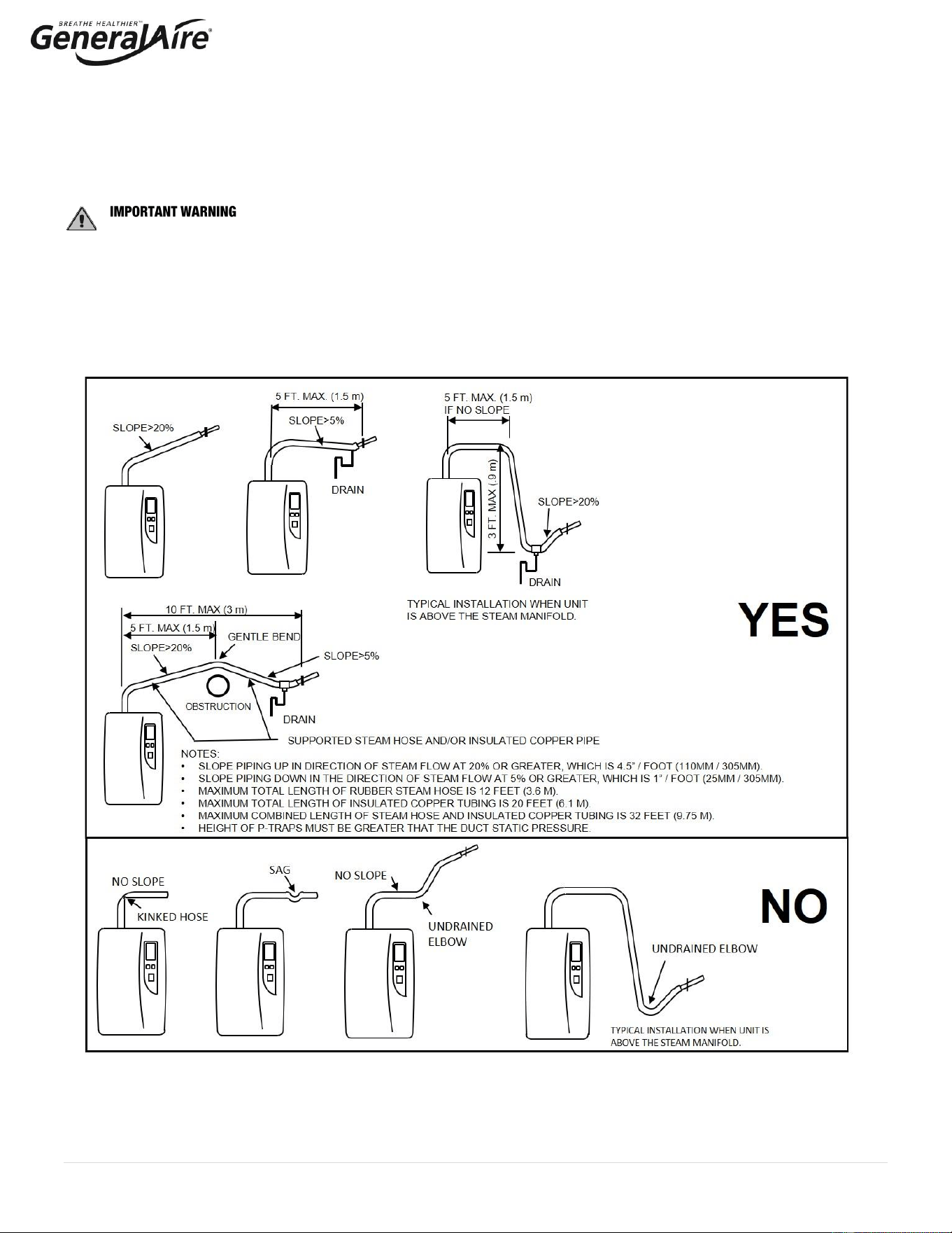
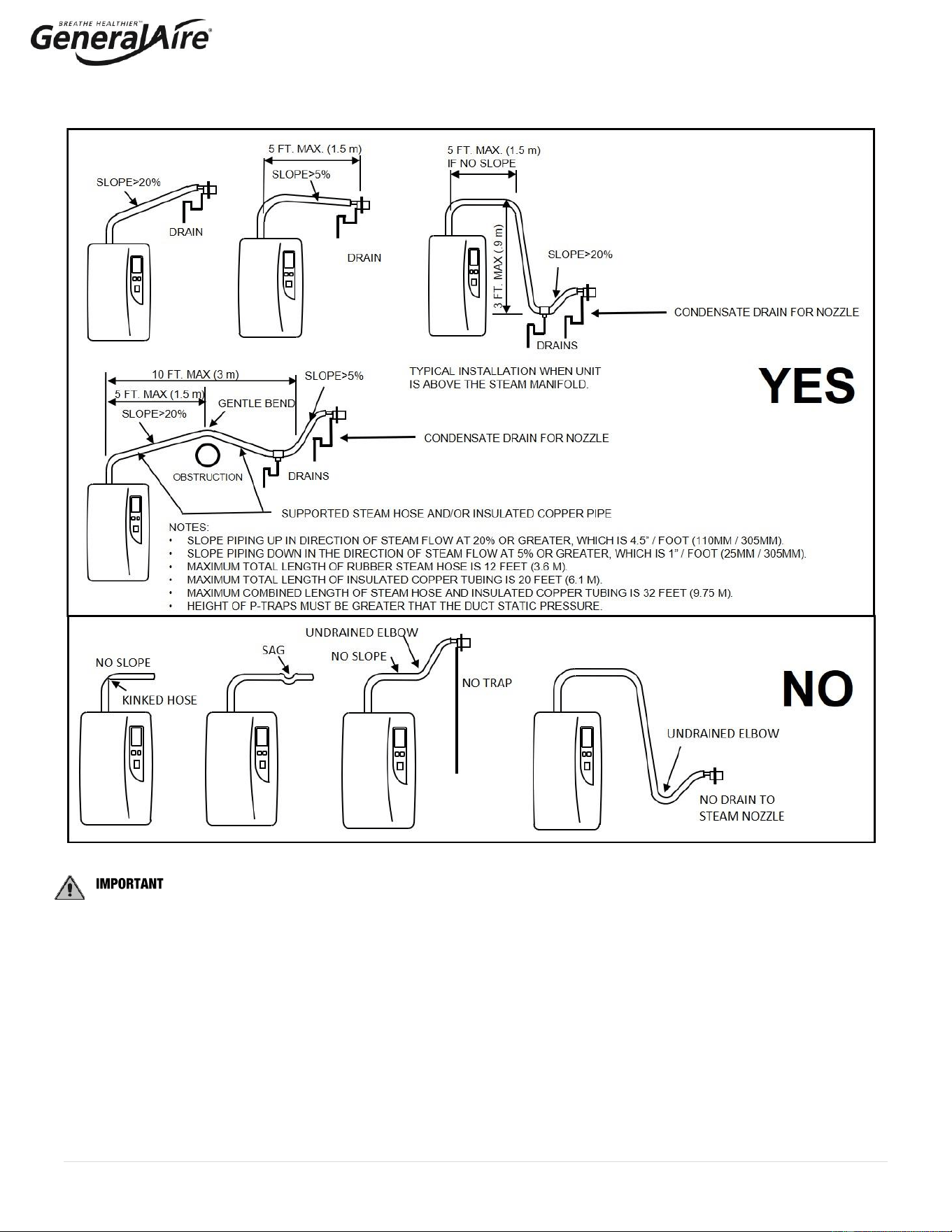
3.4.4 Steam Hoses
: MOST OPERATIONAL PROBLEMS ARE CREATED BY IMPROPER STEAM PIPING FROM THE
HUMIDIFIER UNIT TO THE DUCT DISTRIBUTOR PIPES.
To avoid these problems, remember one simple fact when running the steam hose: steam naturally flows up hill and condensate
naturally flows downhill. Run the steam hose or piping to avoid any kinks, sharp elbows, or low spots that could collect or restrict the
flow of steam to the distributor pipe, or the flow of condensate back to the humidifier. Support the hose adequately to avoid sags.
The following diagrams are provided as guidelines. See Figure 3.l. for the 8” Steam Manifold installation and Figure 3.m. for the
Steam nozzle and 12”/17.5” Steam Manifolds. Contact General Filters for unusual installations.
Figure 3.l. for 8” Steam Manifold – Standard Installation
13 | P a g e
: The standard steam unit comes with 6 feet (1.8m) of steam hose. Maximum total length of rubber steam hose is
3.65m (12 feet). The maximum total length of insulated copper tubing may be up to 6.1m (20 feet). The maximum combined
allowed length of steam hose and insulated copper tubing is 9.75m (32 feet). In all cases, minimize sharp bends and elbows. Use
two 45° elbows instead of one 90° elbows. Hose inner diameter
7
/
8
” (22 mm); Hose outer diameter 1 ¼” (30 mm). Additional steam
hose is available GFI #7513 / CGF #GF-20-2.
3.4.6. Room Steam Kit
Refer to instructions included in the RMB15 (115V) or RMB35 (230V) Room Steam Kit.
Figure 3.m. for Steam Nozzle, 12” and 17.5” Steam Manifold – Optional Installation
14 | P a g e
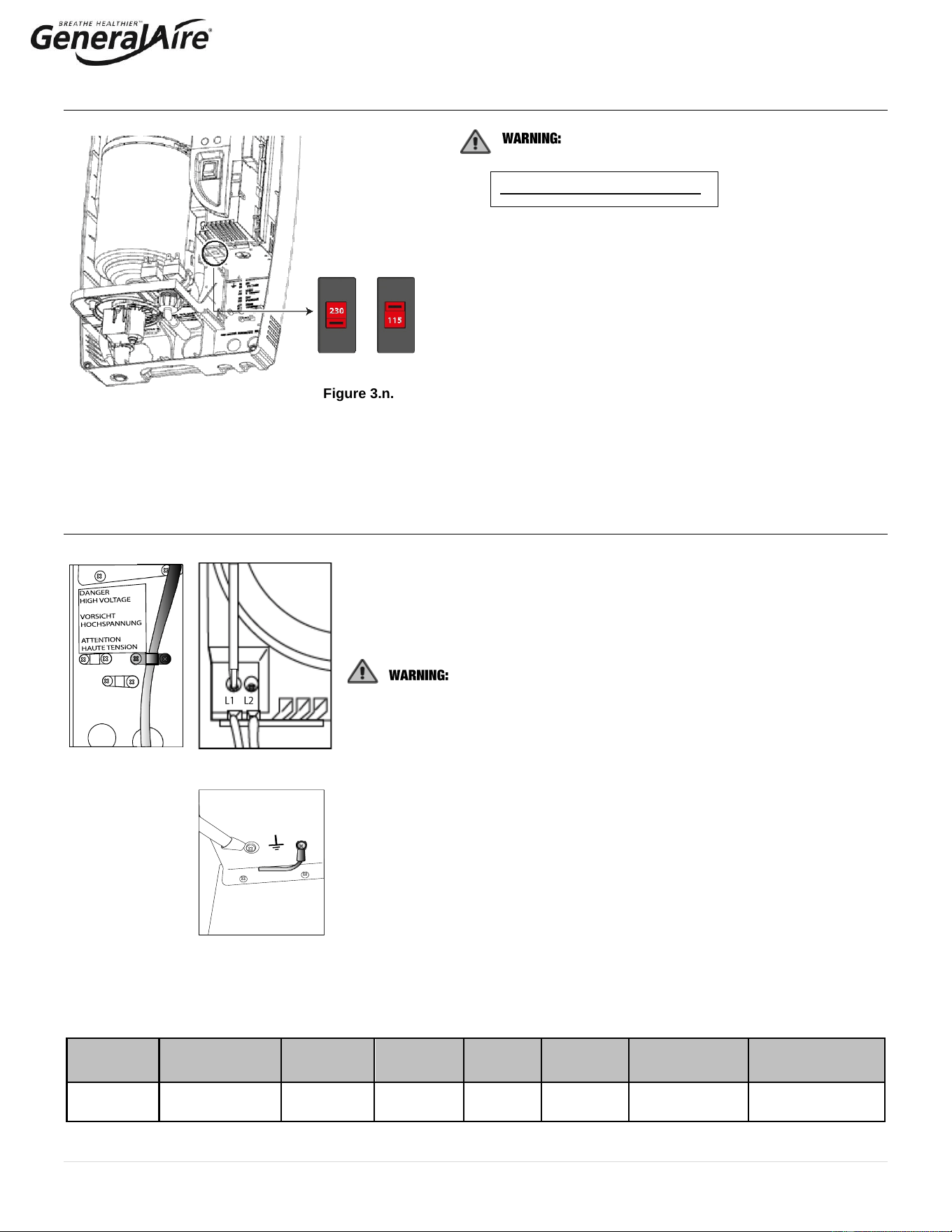
3.5 Power Supply Voltage Selection
Select the desired Power Supply Voltage
Setting!
The factory setting is 230 Vac.
The humidifier can be powered at either a nominal voltage of
115 Vac 50/60 Hertz or a nominal voltage of 230 Vac 50/60 Hz.
If the main power supply is 115 Vac, the setting must be
changed accordingly, following the procedure described below:
1. Make sure the power cable is disconnected from the main
power supply and that the power button is in the OFF
position.
2. Remove the top cover from the unit (see par. 3.2).
3. Set the line voltage selector (shown in figure 3.n.) to the
desired voltage.
3.6 Power Wiring
Insert the power and ground connection cables into the electrical panel compartment
using the cable clamps (See Fig. 3.o.).
Connect the power cables to the terminal block at the bottom left of the control
module, polarity does not matter (See Figure 3.p.).
All wiring must be in accordance with local, state and national electric
codes.
NOTE: to avoid unwanted interference, the power cables should be kept separate
from any control wiring.
NOTE: Tolerance allowed on main voltage = - 15% to + 10%.
Connect the ground wire to the unit’s chassis ground, located just behind the power
wiring terminal block. (See Figure 3.q.)
Model
Power supply
(single phase)
Steam Output
(lbs/hr)
Steam
Output
(kg/h)
POWER
(kW)
CURRENT
(A)
EXTERNAL
POWER WIRES
EXTERNAL FUSE (A)
OR BREAKER
5500
115 - 230Vac
50/60Hz
9.9 @ 230V
4.9 @ 115V
4.5 @ 230V
2.1 @ 115V
3.3 max.
14
AWG10
20
Figure 3.o.
Figure 3.q.
Table 3.e.
Figure 3.n.
Figure 3.p.
15 | P a g e
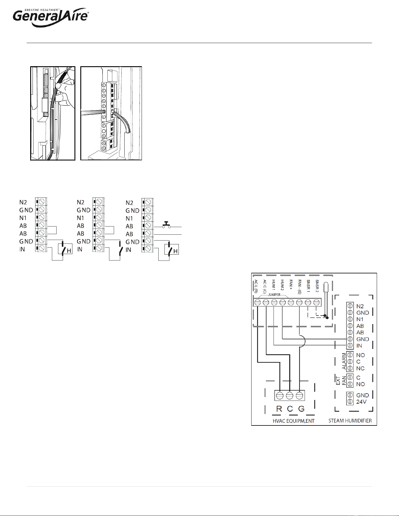
3.7 Control Wiring
5500 Steam Humidifiers allow for the connection of any simple or automatic
humidistat, safety devices such as high-limit humidistat, air flow proving switch, or
remote ON/OFF switch. The control wiring terminal blocks are located at the top
right of the control module ( (Figure 3.r.).
The humidifier is operated by the closing of a mechanical humidistat H, or by the
closing of a voltage-free remote contact, or alternatively by a combination of both.
The most common is a combination of a humidistat and pressure switch. The
diagrams in the figures below show the connections to be made on the terminal block,
in case of:
• Figure 3.s. Operation controlled by an external mechanical humidistat
• Figure 3.t. Operation performed by a simple enabling contact
• Figure 3.u. A combination of both humidistat and pressure switch
Contact AB-AB:
• Closed: humidifier enabled to produce steam (production starts
when humidistat closes).
• Open: steam production is immediately stopped.
• The remote ON/OFF contact is usually a series of external
potential-free contacts that enable the humidifier to produce
steam when all of them are closed, indicating the duct/AHU is
ready to accept steam. Connect the 12500 Pressure Switch NO
and C terminals to the AB-AB contacts.
For Example:
• Fan contact closes when fan is running.
• Downstream cooling coil contact closes when coil is off; etc.
Contact IN-GND:
• Closed: steam production starts if contact AB-AB is closed.
• Open: steam production is stopped after 5 seconds.
3.7.1 Connect the GFX4 Humidistat for ON/OFF Operation (Figure 3.v.)
1. See GFX4 installation manual for complete instructions.
2. Remove the humidistat from the base, squeeze the louvered base at the top
and bottom. To remove the humidistat from the wall, lift up on the humidistat
and pivot top away from wall.
2.2 Before wall mounting, remove the black foam gasket.
2.3 Before return air duct mounting, remove the breakout piece.
3. If return air duct mounting, route wires between humidistat and base.
4. Mount the sensor outside the house. Do not mount on south side of the house
or in direct sunlight. Place at least 4 feet away from any exhaust vent. If in air
intake, place 1 foot or closer to outside wall. Place at least 6” higher than
possible snow. Do not route sensor wire near high voltage wires.
5. Connect the GFX4 and steam humidifier to the HVAC equipment as shown in
Figure 3.u. to activate the HVAC blower.
3.7.2 Modulating Operation
Connect an external 0 to 10 VDC modulating input between terminals IN-GND. Connect any Safety Switches (high-limit, air flow
switch, remote ON/OFF) in series to terminals AB-AB. If no safety switches are used, then a jumper must be installed between
AB-AB. DO NOT apply any voltage to AB-AB.
Figure 3.r.
Figure 3.u.
Figure 3.t.
Figure 3.s.
Figure 3.v.
GFX4
16 | P a g e
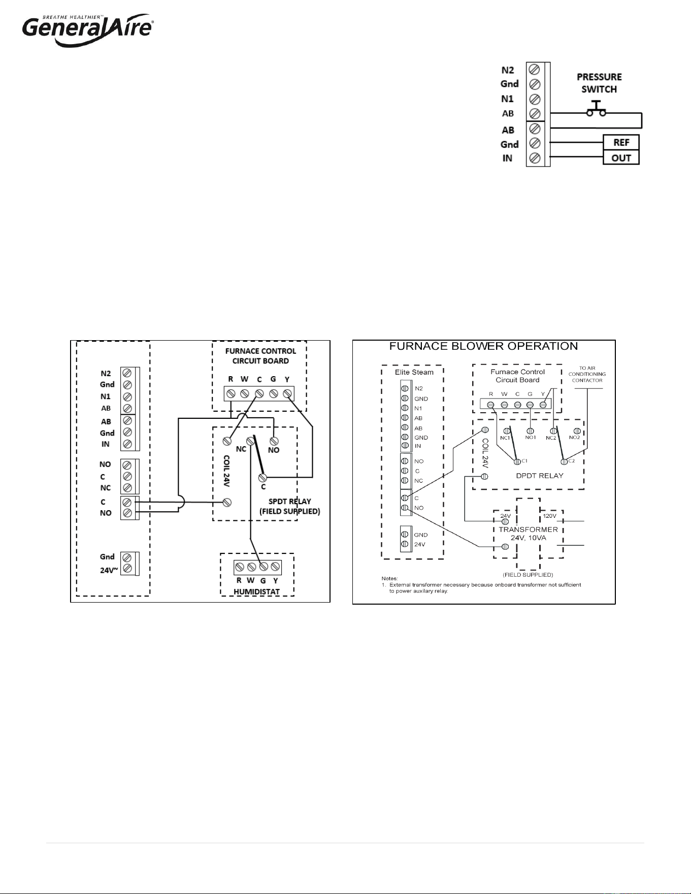
3.7.3 Pressure, Safety, and High Limit Switches (Field Supplied)
Highly Recommended. Remove the jumper between terminals AB-AB and connect any simple
high-limits air flow switch (suggest part HC-201; GFI #7520 or similar); a pressure switch
(suggest part 12500; GFI #7021 or similar), and remote contacts in series to terminals AB-AB;
otherwise, if no such dry contacts are available, the jumper must remain in place between
terminals AB-AB. DO NOT apply any voltage to AB-AB. Thread the control wiring through the
bottom of the unit, and the strain relief (see photo at top of previous page), and then up the side
of the control module to the top right wiring terminal blocks. Connect the control wiring to the
control wiring terminal blocks found at the top right side of the control module. See Figure 3.w.
3.7.4 Furnace Blower Operation / Air Conditioner Relay Interlock
Auxiliary DPDT safety relay: Use this method in the following situations:
1. To prevent the air conditioner from running when there is a call for humidity. The DPDT relay will open the “Y” circuit and close
the “G” circuit for operation while a call for humidity is present (See Figure 3.y.). The demand for humidity will override the call
for cooling.
2. In systems using a thermostat where G and Y are a single circuit, the DPDT relay will allow blower operation to occur without
back-feeding the compressor. DO NOT use this method when simultaneous humidification and cooling will be
desired. Use a high limit humidistat in to avoid condensation in ductwork. The humidistat should be set to OFF during the air
conditioning season if humidification is not desired.
3. For homes without an air conditioner, see Figure 3.x.
4. For variable speed or DC systems, consult the furnace manufacturer.
Figure 3.y.
Figure 3.x.
Figure 3.w.
STEAM 5500
(FIELD SUPPLIED)
17 | P a g e
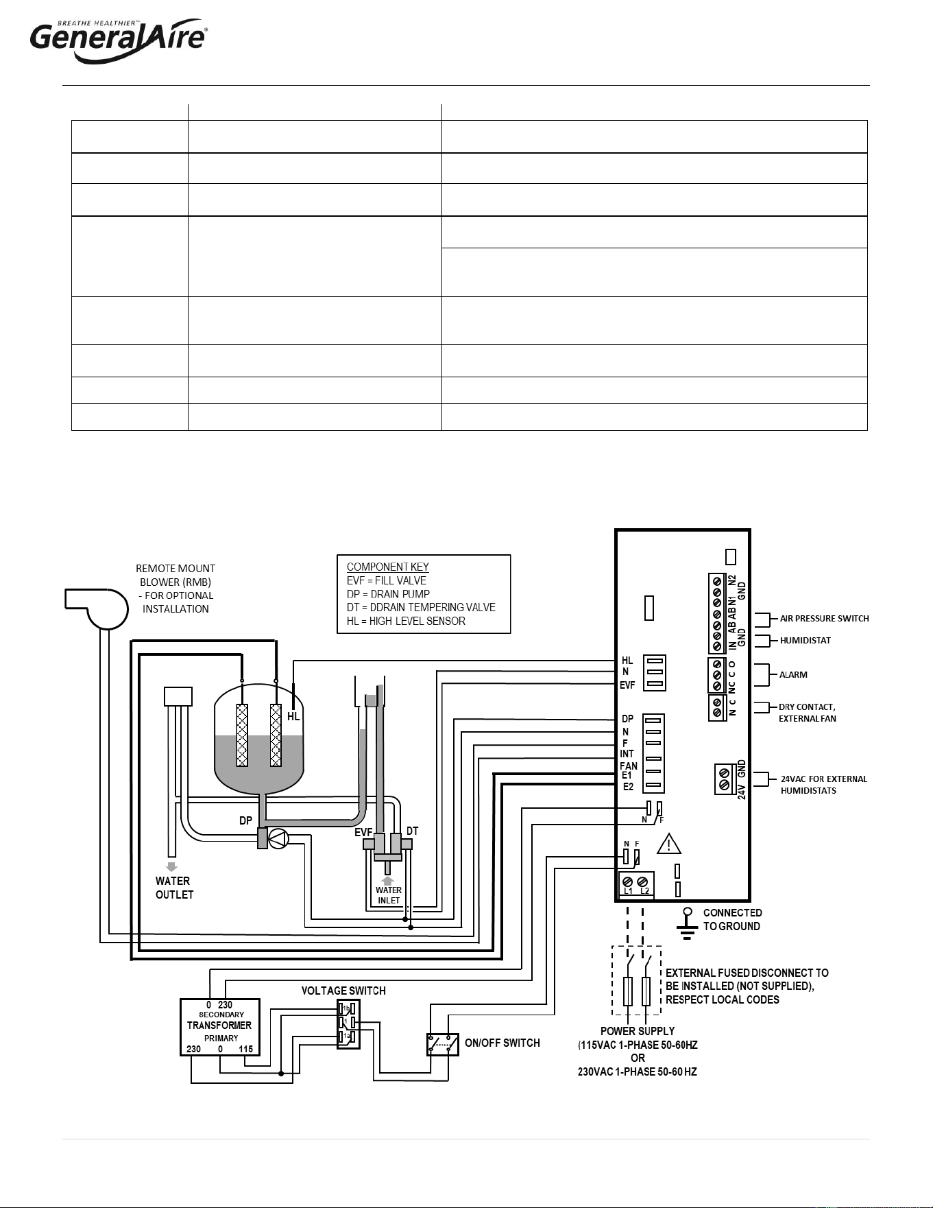
3.8 Wiring Connections
Terminals
Functions
Electrical specifications
L1-L2 -
GROUND
Power supply and ground connections
Power supply 115 VAC 1-phase 50-60Hz 1.86kW or 230 VAC 1-
phase 50-60Hz 4.05kW
KEY
Programming port
Connecting to programming port or supervisor
AB-AB
Remote enabling input
Imposes an external NO contact; Rmax=300 Ohm; Vmax=33 Vdc;
Imax=6mAdc; humidifier enabled = contact closed
IN-GND
Humidistat control signal input
If programmed 0...10V:
Input impedance 10 kohm
If programmed ON-OFF:
Vmax 33Vdc
Imax = 5mA Rmax = 300 Ohm
NC-C-NO
NC alarm contact
Common alarm contact
NO alarm contact
250V; 8 Amp max with resistive load; 4 Amp max with inductive
load
NO-C
External fan relay (furnace blower)
250VAC; 8 Amp max with resistive load; 4 Amp max with inductive
load
24GND
Power for external humidistat
Power supply for external humidistat 24 VAC; 2 Watt
F – INT FAN
For Room Steam Kit
For optional RMB only, not for furnace or air handler connections
3.8.1 Wiring Diagram of Controller
Always use AWG10 wires and dedicated 20A breaker for power supply connections to L1 / 2 in Figure 3.z.
Figure 3.z.
18 | P a g e
4. START-UP
1. Before starting, check that there are no water leaks and that the electrical components are dry.
2. DO NOT connect power if the humidifier is damaged or even partially wet!
When installation is completed, flush the supply pipe for 10 minutes by piping water directly into the drain without sending it into the
humidifier. This will eliminate any scale or residue that may cause foam when boiling.
4.1 Start-Up Checklist
Before starting the humidifier, the following should be checked:
• Water is connected, the line has been flushed, and external valves are open.
• The drain hose is installed with no kinks or restrictions and run to an open drain or condensate pump.
• Electricity is connected in accordance with instructions, local codes and data labels in the unit.
• The power fuses are installed and intact.
• All AWG10 control wiring is done and tested.
• The airflow switch (if installed) is wired to open on air flow loss.
• The Hi-limit humidistat (if installed) is wired to open on humidity rise above set point.
• Control board wires should be checked to make sure all connectors are tight.
• The steam hose and drain hose (and condensate hose, if installed) is run correctly with no sags or kinks and sloped properly
according to the manual.
4.2 Starting the 5500 Steam Humidifier
• Ensure that the external power is turned on.
• Push the top part of the ON/OFF button so that the “1” part is in (See item #13 in figure 4.a.). The yellow power LED will be lit.
The 5500 Steam Humidifier is now ready to operate.
• When there is a call for humidity, the 5500 Steam Humidifier will close its power relays and send power to the electrodes in the
plastic steam generator. The green Operation LED will light, indicating that operation has begun.
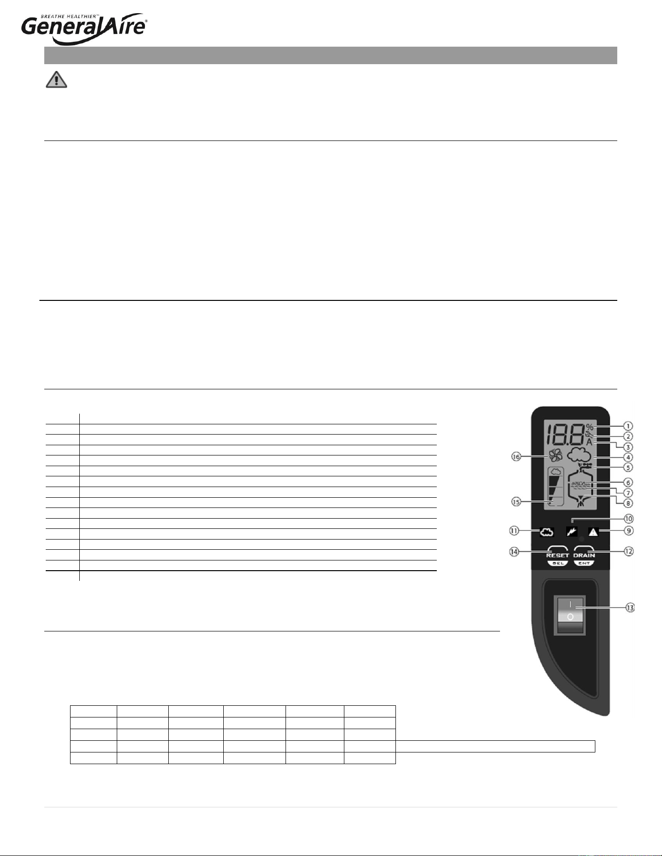
4.3 The 5500 Steam Humidifier Controller
The 5500 Steam Humidifier Controller features a comprehensive information display that shows the
operation of the system at a glance:
1.
Display is % of nominal capacity
2.
Maintenance Alarm
3.
Display is amperage (default)
4.
Steam is being produced
5.
Cylinder filling
6.
Foaming
7.
Water presence inside the cylinder
8.
Cylinder draining
9.
Red LED: alarm
10.
Yellow LED: power (unit is ON)
11.
Green LED: unit is operating
12.
Drain button for manual draining of cylinder and confirming parameter values
13.
ON/OFF button
14.
Reset button to reset alarms and access parameters
15.
Level of output: 33%, 66%, 100%
16.
Fan relay is activated (when fan icon on the control module is stationary, not flashing)
The 5500 Steam Humidifier is now ready to operate.
4.4 Initial Configuration of the Steam Unit
• Before starting the unit, confirm power supply voltage and circuit breaker.
• Confirm the voltage switch is on the correct voltage as described in Section 3.5.
• Press the ON button (item 13), the unit switches on and the display show 03, with the ‘SET’ symbol
flashing.
• Press the ‘RESET/SEL’ button and then adjust the value on the display. Choose the desired value from one
of the four options shown below and press the ‘DRAIN/ENT’ button to confirm.
Option
Voltage
Current
Output
Output
Output
1
115 V
11 A
10.1 gpd
1.6 kg/h
3.5 lb/hr
2
115 V
14.5 A
13.9 gpd
2.2 kg/h
4.9 lb/hr
3
230 V
11 A
20.9 gpd
3.3 kg/h
7.3 lb/hr
Default setting if no selection is made
4
230 V
14.5 A
28.5 gpd
4.5 kg/h
9.9 lb/hr
Figure 4.a.
19 | P a g e
• At the end of this initialization operation, a sequence of characters will be shown on the display to indicate the selected output
and voltage, according to the following scheme:
o CH + size (kg/h) + U + voltage (1 = 115V, 2 = 230V)
1. CH01U1 = 1.6 kg/h 115V
2. CH02U1 = 2.2 kg/h 115V
3. CH03U2 = 3.3 kg/h 230V Default setting is Option 3 if no selection is made
4. CH04U2 = 4.5 kg/h 230V
o If no selection is made within 10 seconds, the unit will start using the default setting Option 3. The unit can be configured
again the next time it is turned on.
o The unit can produce steam even if not configured but the warning ‘EH’ will be shown on the display.
• The yellow power LED comes on and steam unit is ready to operate.
• The green LED ‘cloud’ will light up when the boiler electrodes are powered on and creating steam.
4.5 Starting With A New Steam System or Replacement Steam Cylinder
When starting with a new cylinder, you should activate the cylinder cleaning function as follows:
1. Switch the 5500 Steam Humidifier off.
2. Press and hold both buttons, “RESET/SEL” and “DRAIN/ENTER”, and switch the 5500 Steam Humidifier back on. When the
wrench blinks then release the two buttons.
3. Press and hold “RESET/SEL” until the display shows 04.
: DO NOT confirm any value higher than 04. If 05 or higher is displayed, press “RESET/SEL” until the display
goes back to the normal operating mode and restart from step 1.
4. Press “DRAIN/ENTER” (minimum 1 second): the cleaning starts and the display shows PC.
During the cleaning, the electrodes are powered and water in the cylinder rises until it touches the high-level sensor or reaches the high current
limit; whichever comes first . After either of the events is detected, the boiler is fully discharged with the electrodes un-powered (the drain pump
and the drain tempering valve are activated for 3 minutes). It is recommended that two cleanings are performed when starting a new steam
unit. After the cleaning ends, the humidifier begins its regular function. When starting the unit with a new or empty cylinder, it may take a
significant amount of time (hours) for the unit to build up enough mineral concentration to reach rated capacity. This time can be shortened by
the addition of a teaspoon of salt or ¼ of an antacid tablet through the steam outlet on top of the cylinder.
5. Operating the 5500 Steam Humidifier
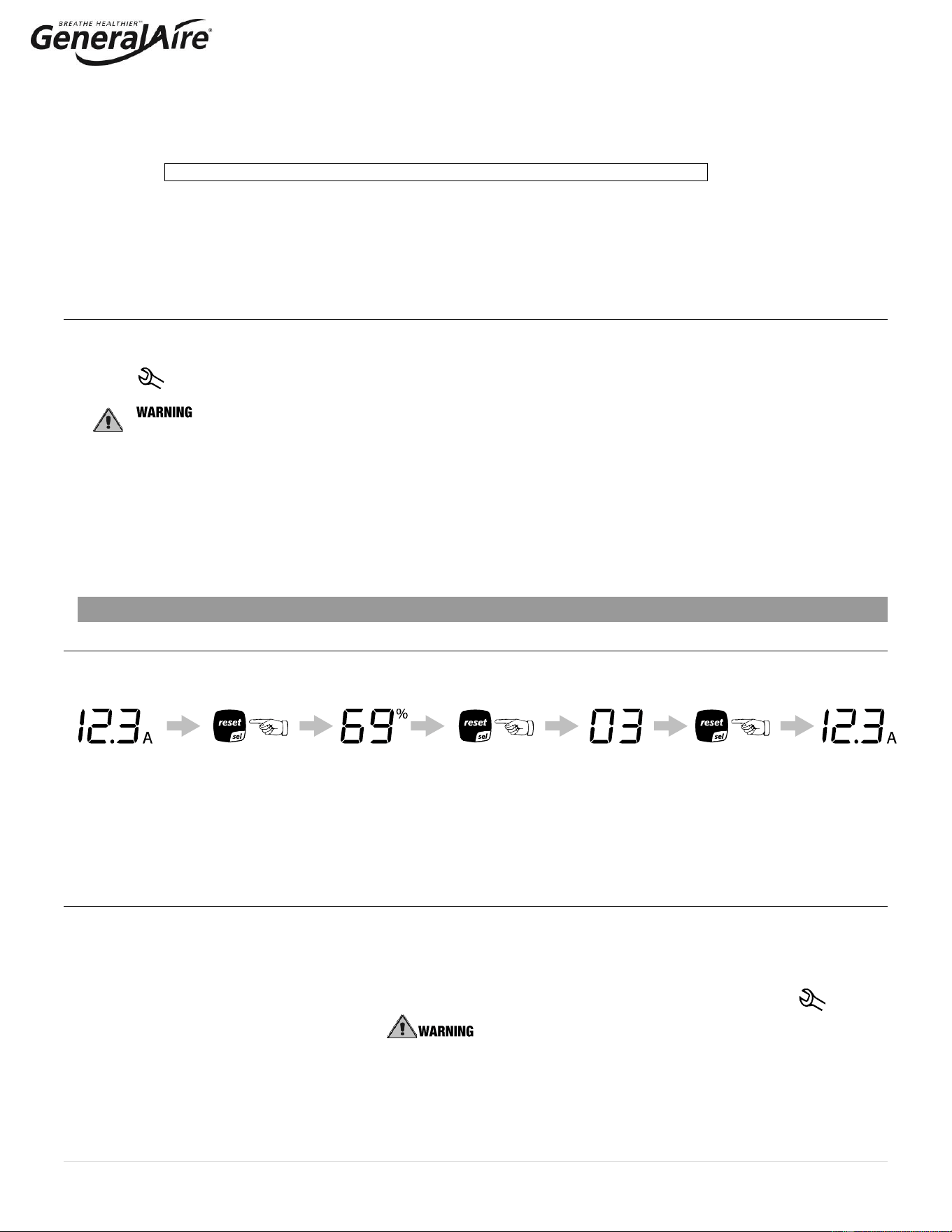
5.1 Displaying Information
By pressing the “reset” button for 2 seconds, the display will loop from amperage to production in % of the maximum production to
the hour counter and back to amperage:
Figure 5.a
1. Amperage: it is the value of the current that flows through the water, causing it to boil (default display).
2. Production %: it is the current production expressed as a percentage of the humidifier’s capacity.
3. Hour counter: counts the operating hours, proportional to the % of cylinder production (this must be reset whenever the
cylinder is replaced). For example, if the cylinder has worked for 100 hours at 50% production, the number of proportional
operating hours is 50. The value is expressed in tens of hours, so for example when the display shows 13, the real number of
operating hours is between 130 and 139 hours. Once 1990 hours have elapsed (199 on the display), the hours are displayed in
hundreds. Example: 21 = 2100 hours.
5.2. Select Signal Type
The steam humidifier is pre-set for the included GFX4 humidistat (signal type 0). If the included GFX4 humidistat is used, this
section may be omitted. If another humidistat is used, review this section to see if changes are needed.
Note: select the correct control signal type on the keypad before connecting the control wiring. If no selection is made within 3
seconds, the software automatically returns to normal operating mode.
1. Switch steam humidifier off.
2. Press and hold both buttons “reset” and “drain” and switch the 5500 Steam Humidifier back on. When the wrench blinks,
release the two buttons.
3. Press “RESET/SEL” until the display shows 02. : DO NOT confirm any value higher than 04. If 05 or higher is
displayed, press “RESET/SEL” until the display goes back to the normal operating mode and restart from step 1.
4. Press “DRAIN/ENTER” (minimum 1 second) to confirm: the display shows “P1” then the current signal type and “set”.
5. Press “RESET/SEL” to change signal type between 0 and 1:
0 = On-Off humidistat such as the GeneralAire
®
“M” or “GFX” series humidistat.
1 = external 0...10 Vdc modulating signal such as the GeneralAire
®
ADCD series humidistat.
6. Press “DRAIN/ENTER” (minimum 1 second) when done to confirm the new value of P1 and exit to the normal operating mode.
7. Switch steam humidifier off: you can now proceed with connecting the control wiring.
20 | P a g e
5.3. Changing the Maximum Production
The Maximum Production feature can be adjusted between 20% to 100% of the nominal production, in 5% increments, in order to
suit the environmental characteristics. The 5500 Steam Humidifier is factory set at 100%.
1. Switch steam humidifier off.
2. Press both and hold both buttons “RESET/SEL” and “DRAIN/ENTER” and switch steam humidifier back on. When the wrench
blinks, release the two buttons.
3. Press “RESET/SEL” until the display shows 01. : DO NOT confirm any value higher than 04. If 05 or higher is
displayed, press "reset" until the display goes back to the normal operating mode and restart from step 1.
4. Press “DRAIN/ENTER” (minimum 1 second) the display shows “P0” then the current Maximum Production Percent and “set”.
5. Press “RESET/SEL” to change the Maximum Production in steps of 5% between 20% and 100%.
6. Press and hold “DRAIN/ENTER” (minimum 1 second) when done to confirm the new Maximum Production and exit to the
normal operating mode.
5.4 Activating Manual Drain
Press and hold the “DRAIN/ENTER” button on the front of the unit until the cylinder is drained. Note: Water will continue to flow from
the tempering valve after the cylinder is empty.
5.5 Resetting the Hour Counter With New Cylinder Replacement
The hour counter should be reset every time the cylinder is changed in order to reset and restart the internal maintenance timer:
1. Switch the steam humidifier off.
2. Press and hold both buttons “RESET/SEL” and “DRAIN/ENTER” and switch the steam humidifier back on. Hold the buttons
until the wrench blinks and the display shows ‘00’; release buttons.
3. Press and hold “RESET/SEL” until the display shows 03. : DO NOT confirm any value higher than 04. If 05 or
higher is displayed, press “RESET/SEL” until the display goes back to the normal operating mode and restart from Step 1.
4. Press “DRAIN/ENTER” (minimum 1 second) to confirm: the hour counter will be reset at once and the steam humidifier will go
back to the normal operating mode.
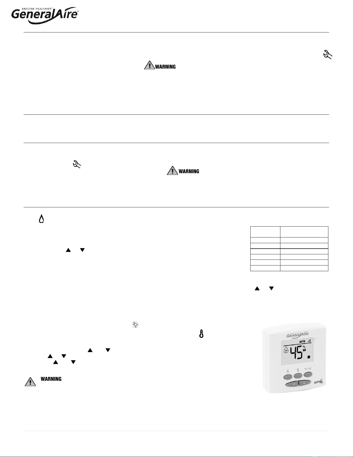
5.6 Using the GFX4 Humidistat
See GFX4 installation manual for complete instructions.
Press to select OFF, AUTO (if outdoor sensor is connected) or MANUAL mode.
OFF mode: The humidifier is turned off.
MANUAL mode:
The GFX4 will work to maintain the single humidity selected. You can set your desired humidity
level by pressing or . The humidifier will turn ON or OFF according to your manual setting.
(The humidifier will operate when the measured relative humidity falls more than 2% below the set
point.) Humidity will have to be lowered when weather is colder or if condensation is suspected.
AUTO mode:
The GFX4 will automatically raise the humidity as the outdoor temperature increases. This provides the highest possible humidity.
The GFX4 will automatically lower the humidity as temperatures drop. This minimizes the risk of condensation on cold surfaces like
windows. You can adjust the Auto Humidity Index Set Point from 0 (low) to 10 (high) by pressing or . The Humidity Index is
based on the outdoor temperature and indoor humidity. The humidifier will switch ON/OFF according to the calculated auto humidity
index set point. Lower Index settings are for older homes with less insulation and vapor barriers. Higher Index settings are for newer
homes with complete vapor barriers, triple pane windows and high R value insulation. If condensation occurs reduce Index setting by
2 points until condensation stops.
NOTE If the outdoor temperature sensor fails, flashes and the unit will default to MANUAL mode.
To toggle between indoor / outdoor temperature and indoor humidity: Press .
To change the temperature unit: Press °C / °F.
To set the temperature / humidity offset in MANUAL or AUTO mode:
1. Simultaneously press and when viewing the temperature or humidity reading.
2. Use or to change the setting (-3 to 3).
3. Press and simultaneously or wait 5 seconds to confirm, then move onto the next setting.
: DO NOT allow excess humidification.
Excess humidity can cause condensation and enable mold and mildew growth.
Suggested
Setting
Outdoor
Temperatures
15%
-20˚F / -29˚C
20%
-10˚F / -23˚C
25%
0˚F / -18˚C
30%
+10˚F / -12˚C
35%
+20˚F / -7˚C
40%
+30˚F / -1˚C
Table 5.a
GFX4 HUMIDISTAT

21 | P a g e
5.7 Alarms
In the event of an alarm, the red alarm LED will flash, the alarm relay will close, and the alarm code will flash in the display. Multiple
alarms will flash in sequence, alternating with the main display. Pressing the “RESET/SEL” button for 2 seconds will reset the
alarms, although still active alarms will continue to display.
Display
Description
Action
Red
Led
Alarm
Relay
Notes
--
Remote on-off open
Unit disabled
Off
Off
Jumper terminals AB-AB
EH
Unit not configured.
If no selection is made within 10
seconds, the unit will start using
the default setting Option 3.
On
On
Unit will produce
steam. The unit can be
configured again the next
time it is turned on.
E1
High current alarm
Unit disabled
On
On
Turn off, check connections,
check cylinder (no limescale
bridges between electrodes,
no electrodes short-circuited)
E2
Low production, low supply
water conductivity or
excessive foam/limescale in
the cylinder
Unit disabled
Press “RESET/SEL” key for 1
second to reset
On
On
Check supply water
conductivity, replace the
cylinder.
E3
Cylinder almost exhausted
Press “RESET/SEL” key for 1
second to reset
Off
Off
Change cylinder (not urgent)
E4
Fill alarm, unable or slow
fill (current does not
increase within timeout)
Press “RESET/SEL” key for 1
second to reset, otherwise the
warning will be reset automatically
every 10 minutes until the supply
water is available again
On
On
Check water supply and fill
valve; check drain pump for
leakage;
Make sure the filter on the fill
solenoid valve is not blocked;
check that the steam outlet is
not
working against excessive
backpressure; check that the
steam outlet hose is not
choked or that there are no
pockets of condensate;
check that the power cables
are connected to the cylinder.
E5
Drain alarm, unable to drain
(current does not decrease
within timeout)
Press “RESET/SEL” key for 1
second to reset
On
On
Check drain pump and drain
connection
E7
Foam detected
Press “RESET/SEL” key for 1
second to reset
Off
Off
If foam continues, perform
additional cleaning cycles.
E8
Cylinder lifetime expired
Unit disabled: reset the hour
counter (read chap. “Resetting the
Hour Counter”)
On
On
Change the cylinder if
necessary
E9
High controller temperature
(above 176°F / 80°C)
The warning is automatically reset
if the temperature decreases
below 176 °F / 80 °C
Off
Off
Check the ambient
temperature, replace the
controller

22 | P a g e
6. TROUBLESHOOTING
Table 6.a
Problem
Causes
Solutions
The humidifier does not turn
on
1. No electrical power
2. ON/OFF switch of the humidifier in position 0
(open)
3. Control connectors improperly connected
4. Blown fuses
5. Transformer failure
1. Check the safety devices upstream from the humidifier
and the presence of power
2. Close the switch on the panel: position I
3. Check that connectors are properly inserted in terminal
block
4. Check the condition of fuses
5. Check that the proper voltage is connected and turned
on
The humidifier does not start
operation
1. Remote ON/OFF contact open
2. The humidistat has not been connected
correctly
3. Humidistat failure
4. Control signal not compatible with the type set
5. Value measured by the sensor/s higher than
the corresponding set point
6. Fan relay not activated, or furnace blower not
activated or connected to C/NO on steam
humidifier
1. Close ON/OFF contacts
2. Check the external connection
3. Replace the humidistat
4. Check furnace fan / blower operation
The humidifier fills with water
without producing steam
1. High steam back pressure
2. Fill valve strainer clogged
3. Mineral in the fill cup
4. Drain pump valve leaking
1. Check that the steam hose is not kinked or sagging,
trapping condensate
2. Clean the fill valve strainer
3. Clean the fill cup
4. Check for voltage at the drain pump valve and/or drain
pump replacement
Excess humidity or moisture
in the duct
1. The distributor is not installed correctly (too
near the top of the duct or the condensate
return is blocked)
2. Air flow rate is too low
3. Humidifier active when the fan in the duct is off
1. Check that the steam distributor is installed correctly
2. Increase air flow in duct or decrease PO maximum steam
production setting
3. Check the connection of the device (flow switch or
differential pressure switch) controlling the humidifier to
the ventilation in the duct
Water leaks on to the floor
below
1. The humidifier drain is blocked
2. The supply water or overflow circuit has leaks
3. The steam hose is not properly fastened to the
cylinder
4. The bushing and / or O-ring at the base of the
cylinder are missing or not properly seated
1. Clean the drain assembly and pan
2. Check the entire water circuit
3. Check the fastening of the hose clamps on the steam
outlet
4. Lift out the cylinder and check to see the bushing and / or
O-ring are properly seated (See illustration Page 21)
Water in the cylinder turns
black
1. Minerals in the cylinder have over-concentrated
and are deteriorating the electrodes
1. Check for sags & kinks that could trap condensate in the
steam hoses that could cause a back pressure on the
cylinder
2. Check the duct static pressure
3. Check the fill valve and inlet strainer
4. Check the drain pump operation
5. Correct installation problems and replace cylinder
Heavy arcing occurs within
hours of start-up
1. The feed water contains large amounts of iron,
copper or other conductive contaminants
1. Contact the factory for an optional drain timer to force
additional drains to control the minerals
2. Discontinue use if you are using a water softener
3. Check the electrodes in the cylinder to be sure they were
not damaged in shipping
Humidifier continuously fills
and drains without producing
steam
1. Mineral has bridged between the electrodes
2. There is back pressure from the steam hoses
or duct
3. The flow regulator in the fill valve is broken or
out of place
4. Water conductivity is very high
5. Water is foaming excessively
1. Use instruction in Section 4.4 to power clean or replace
the cylinder
2. Check the steam hoses for kinks or gullies that might be
trapping condensate
3. Replace the fill valve
4. Consider using a mix of demineralized water with raw
water
5. Check cylinder - replace if exhausted. If feed water
contains silica or nitrates, install a 1-micron water filter
23 | P a g e
7. MAINTENANCE
7.1 Periodic Checks
• After one hour of operation: Check that there are no significant water leaks.
• Every fifteen days: Check operation for water leaks and the general condition of the cylinder. Check that during operation there is no
arcing between the electrodes.
• Every three months: Check operation for water leaks and, if necessary, replace the cylinder. Check that there are no blackened
parts of the cylinder. If there are blackened parts of the cylinder, check the condition of the electrodes and, if necessary, replace the
cylinder.
• Annually: Replace the cylinder.
: ALWAYS disconnect the main power before doing maintenance.
: ALWAYS disconnect the main power before touching the cylinder that has leaked, as current may flow through the water.
7.2 Cylinder Maintenance
The life of the cylinder depends on a number of factors, including the amount and type of mineral in the water, the correct use and sizing of
the humidifier, the output setting, and careful and regular maintenance. Another factor in affecting cylinder life is maximum production, which
can shorten the cylinder life. The 5500 is pre-set from the factory at 100%. Reducing the factory setting at maximum production will extend
cylinder life. (See Figure 7.a)
The humidifier and its cylinder contain live electrical components and hot surfaces; therefore, all service and/or
maintenance operations must be performed by expert and qualified personnel, who are aware of the necessary
precautions. Before performing any operations on the cylinder, check that the humidifier is disconnected from the
power supply. Remove the cylinder from the humidifier only after having drained it completely using the manual
“drain” button or procedure. Check that the model and the power supply voltage of the new cylinder correspond to
the data on the rating label.
7.2.1 Replacing the Cylinder
the cylinder may be hot. Allow it to cool before touching it or use protective gloves.
DO NOT attempt to clean the cylinder or its components. Damage may result that will affect operation and void the warranty.
To Replace the Cylinder:
1. Completely drain the cylinder by pressing and holding the “drain” button until the cylinder is empty.
2. Turn the humidifier off and disconnect the main power.
3. Remove the cover by unscrewing the single screw at the center bottom of the cover.
4. Disconnect the electrical connections from the cylinder.
5. Flip up the cylinder holding bracket and lift the cylinder out of the unit. Some water may spill out from the bottom of the cylinder.
6. Install a new O-ring if necessary. The O-ring only needs to be replaced if worn, damaged, or lost. (See Figure 7.b.)
7. Install the new cylinder in the humidifier by performing the previous operations in reverse.
a) Connect the power cables to the electrodes in the cylinder, inserting the “snap-on” wire caps as shown on the yellow cylinder
label. Make sure the connector is inserted correctly (you will hear a “click” when in place).
b) Replace the steam hose to the cylinder and tighten the hose clamp.
: DO NOT tighten the 7/8” hose clamp so tight that it crushes the cylinder outlet.
: Electrical connections to the cylinder must be properly installed. Listen for, and feel a significant
“click” on connection or possible fire hazard may result.
7.2.2 Maintenance of The Other Plumbing Components
• External power must always be disconnected when performing any maintenance on the humidifier.
• When cleaning the plastic components do not use detergents or solvents.
• Scale can be removed using a solution by using vinegar or a weak solution of acetic acid and a soft brush,
then rinse the plumbing components (drain pump, fill/tempering valve, water line fill connector) thoroughly with fresh water.
Cleaning the Fill Valve:
• Disconnect the cables and the hoses, remove the valve and check the condition of the inlet filter; clean if necessary, using a
cleaning solution and a soft brush.
Cleaning the Drain Pump:
• Remove the valve body, clean if necessary, using the same cleaning solution as for the steam cylinder and a soft brush.
Cleaning the Drain Pan:
• Clean the pan of any mineral deposits and check that the water flows freely from the pan to the drain at the drain pump.
Cleaning the Supply, Fill, Overflow Pipes:
• Check that these are clear and clean or replace if necessary.
after having replaced or checked the plumbing, check that components have been reconnected correctly with
the proper seals. Re-start the humidifier and perform several cleaning cycles (from 2 to 4, read section “Initial configuration of the
Steam Unit”.)
Red O-Ring
Figure 7.a.
Figure 7.b.
24 | P a g e
7.3 Replacement Parts
Item
USA
GFI
Part No.
CANADA
CGF
Part No.
Description
1
7746
GF-55
MODEL 55 REPLACEMENT STEAM CYLINDER
2
7747
GF-5500-03
5500-03 CONTROL MODULE ASSEMBLY 115V/230V
3
7551
GF-35-18
35-18 ON/OFF SWITCH
4
7753
GF-5500-08
5500-08 FILL & DRAIN TEMPERING VALVE 230V
5
7805
GF-25-7
25-7 KIT FOR DRAIN PUMP 230V
6
7806
GF-25-2
25-2 FILL TANK + PLUG FOR DRAIN PUMP
7
7810
GF-25-8
25-8 DRAIN TANK + PLUG FOR DRAIN PUMP
8
7808
GF-35-25
25-5 DUCT TUBING KIT FOR DRAIN PUMP
9
7553
GF-35-25
35-25 COVER HOLDING SCREWS FOR CH SERIES
10
7809
GF-25-6
25-6 BOTTOM TANK FOR DRAIN PUMP
11
7750
GF-5500-06
5500-06 STRAIGHT DRAIN FITTING
Not Shown
7513
GF-20-2
20-2 STEAM HOSE 7/8” I.D.
Not Shown
7748
GF-5500-04
5500-04 INTERNAL WIRE KIT
Not Shown
7749
GF-5500-05
5500-05 DRAIN HOSE 3/4" I.D.
Not Shown
7751
GF-5500-01
5500-01 MOUNTING STRAPS
Not Shown
7752
GF-5500-07
5500-07 8" STEAM MANIFOLD
Exploded View of O-Ring Placement
• Bushing is permanently affixed to drain pump.
• O-ring is included with replacement cylinder.
1
3
5
10
6
2
8
4
9
12
12
4
5
1
3
8
6
14
10
11
7
9
12
2
15
11
7
5
25 | P a g e
8. TECHNICAL SPECIFICATIONS
Specification
Description
Notes
Capacity / VAC / kW
4.9 lbs/hr (2.2 kg/h): 115 VAC 1-phase 50-60 Hz, 1.86 kW
9.9 lbs/hr (4.5 kg/h): 230 VAC 1-phase 50-60 Hz, 4.05 kW
Steam pressure
3.81 in WC / 950 Pa (.137 PSI)
For duct only
Dimensions (inches / mm)
21” H x 13” W x 8.25” DP (533 x 343 x 210 mm)
(Height x Width x Depth)
Weight
empty/packaged/installed with
water (pounds / kilograms)
16 / 26 / 24 lbs. (7.3 / 12 / 11 kg)
IP class
IP20
Electrode power cables
12 AWG
Power relays (Amps)
2 x 30
On board
Ground connection
Screw
Input water type
Potable water
No demineralized or softened water
Conductivity range
(microSiemens)
125-1250 µS/cm
Water fill connection
1/4” O.D. Compression
Adapter to 3/4" BSP
Water fill - instant flow
0.09 – 0.16 gpm (0.35 – 0.60 l/min)
Drain Hose
¾” ID x 10 ft. drain hose supplied (19 mm ID)
From bottom of unit
Drain water temp F / C
< 140°F ( < 60°C)
Drain tempering device
Drain flow
Initial Max drain rate using ¼” OD supply tubing and full
cylinder – approx 1.1 gallons for first 15 secconds of drain
cycle (~4.4 gpm (13.2 l/min)).
Initial Max drain rate using hose with ¾” BSP fitting – 6.3
gpm (23.8 l/min).
Average drain rate – 3.8 gpm (14.4 l/min) (measured over a
one minute period starting with full cylinder)
Serial communication
DS485
Unit voltages
Primary 115 / 230 Volts AC / Control Wiring 12 Volts DC
Electrical requirements
Require AWG10 external power wires to electrical panel with a dedicated 20A.
Max output
28.5 GPD max. If unit is not configured (section 4.4) then default setting from factory is 20.9 GPD
at 230V.
Steam hose
6‘ BLUE STEAM HOSE ID 7/8" (22mm), OD 1 ¼“ (30mm), (GFI #7525)
8“ Steam manifold (standard)
8“ steam manifold supplied with Duct Mounting Kit
OPTIONAL
GF-12500 air pressure switch
Actuated by positive, negative or differential presure of .05“ W. C. Or more (GFI #7021)
RMB15 room steam kit
115V Includes room blower assembly and grille package (GFI #7665)
RMB35 room steam kit
230V Includes room blower assembly and grille package (GFI #7660)
Steam nozzle
Optional accessory can be used for bottom duct installation (GFI #7500 / CGF#GF-20-1))
GF-DPO30KIT
Optional accessory 12" length distribution manifold (GFI #7521)
GF-DP045KIT
Optional accessory 17.5" length distribution manifold (GFI #7522)
FIELD SUPPLIED
Copper tubing
OD 3/4" to fit ID of blue steam hose
Inline pre-filter
Any activated carbon element and particulate element rated for 5 micron or less and min 25 GPM
Condensate pump
3 gpm min. flow at 0 head and 1 gallon reservoir min. The technician is responsible for selecting
the appropriate condensate pump for the installation.
26 | P a g e
9. LIMITED WARRANTY
GeneralAire
®
Model 5500 Steam Humidifiers, if properly registered on www.generalfilters.com/support/warranty-registration, are
warranted to the consumer against defects in materials and workmanship for a period of five years from the date of installation, so
long as the product has been installed by a qualified contractor and operated in accordance with all appropriate manuals and wiring
diagrams in a residential structure.
Installation in commercial, industrial or office building locations will void all warranties. Installation to a water source that does not meet
unit specification will void all warranties. Replacement of routinely replaceable parts such as steam cylinders and gaskets, are not
covered by this limited warranty or any other warranties.
Any other defective parts will be repaired without charge except for removal, reinstallation and transportation costs. To obtain repair
service under this limited warranty, the consumer must send the defective part to General Filters, Inc.
THERE ARE NO EXPRESS WARRANTIES COVERING THIS HUMIDIFIER OTHER THAN AS SET FORTH ABOVE. THE IMPLIED
WARRANTIES OF MERCHANTABILITY AND FITNESS FOR A PARTICULAR PURPOSE ARE EXPRESSLY EXCLUDED. THE
MANUFACTURER ASSUMES NO LIABILITY IN CONNECTION WITH THE INSTALLATION OR USE OF THIS PRODUCT, EXCEPT
AS STATED IN THE LIMITED WARRANTY. THE MANUFACTURER WILL IN NO EVENT BE LIABLE FOR INCIDENTAL OR
CONSEQUENTIAL DAMAGES. This limited warranty gives you specific legal rights, and you may also have other rights which vary
from state to state. Some states do not allow either limitations on implied warranties, or exclusions from incidental or consequential
damages, so the above exclusion and limitation may not apply to you.
Any questions pertaining to this limited warranty should be addressed to General Filters, Inc. General Filters, Inc. has elected not to
make available the informal dispute settlement mechanism which is specified in the Magnuson-Moss Warranty Act.
Register your warranty online USA: www.generalfilters.com / Support
Register your warranty online Canada: www.cgfproducts.com / Warranty Registration
GENERAL FILTERS, INC CANADIAN GENERAL FILTERS, LLC.
43800 GRAND RIVER AVENUE 400 MIDWEST ROAD
NOVI, MI. 48375 TORONTO, ON M1P3A9
(866) 476-5101 (888) 216-9184
www.generalfilters.com www.cgfproducts.com

27 | P a g e
This Page Left Intentionally Blank