TRION
®
| www.trioniaq.com
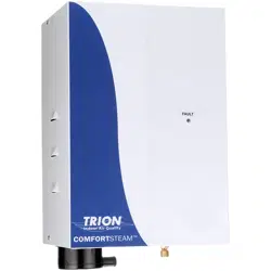
COMFORTSTEAM
TM
CFS20 & CFS22
Humidication System Series
READ AND SAVE THESE INSTRUCTIONS
UNITS NOT FOR COMMERCIAL USE

Installation, Operation, & Maintenance Manual
2 www.trioniaq.com
TABLE OF CONTENTS
SECTION I WARRANTY
Preface ...........................................................................................................................................................3
SECTION II UNIT OPERATION
Basic Operation Overview .............................................................................................................................. 4
What’s in the Box ............................................................................................................................................4
Key Features ..................................................................................................................................................5
Engineering & Application...............................................................................................................................6
SECTION III INSTALLATION INSTRUCTIONS
Mounting .........................................................................................................................................................7
Plumbing.........................................................................................................................................................7
Steam Distribution ..........................................................................................................................................8
Wiring .............................................................................................................................................................9
Supply Power .................................................................................................................................................9
Control Circuit Connections ............................................................................................................................9
SECTION IV OPERATING INSTRUCTIONS
Installation Checklist .......................................................................................................................................10
Start-up Instructions .......................................................................................................................................11
Maintenance ................................................................................................................................................... 12
SECTION V TROUBLESHOOTING GUIDE
Board Test Points ...........................................................................................................................................13
Unit Detected Faults: (Red Service Light On) ................................................................................................14
Non-fault Activated Problems .........................................................................................................................15
Wiring Diagrams ............................................................................................................................................. 17
Exploded View ................................................................................................................................................ 18
Parts List.........................................................................................................................................................19
ComfortSTEAM
®
CFS20 & CFS22
Installation, Operation, & Maintenance Manual
3
www.trioniaq.com
7. This Warranty gives you specic legal rights, and you
may also have other rights which vary from state to
state.
NOTE: Water quality plays a vital role in the performance
and maintenance requirement of any humidier.
Adjustments to the circuit board may be necessary based
on the incoming water quality. See pages 13-16.
Performance problems associated with water quality are
not warranty issues!
SECTION I WARRANTY
Warranty
1. TRION warrants to the buyer or any user during the
duration of the Warranty that the humidier described
in this manual will be free from defects of material and
workmanship for a period of 24 months from install
or 30 months from shipment (excludes replaceable
steam cylinder), whichever comes rst.
2. For this Warranty to be effective, this humidier must
be installed, operated and maintained in accordance
with the Installation Instructions, Operations and
Maintenance Manual(s) supplied with the humidier.
3. In the event of a defect or malfunction in this product during
the Warranty Period, user may contact the Customer
Service Department or their TRION Representative for a
Customer Relations Management (CRM) number. Items
tagged (on the outside of the box) with this number
may be returned to TRION for replacement. Incidental
expenses such as cost of transporting the humidier to
TRION or labor associated with removal/replacement of
the parts shall be paid by the user. Upon completion of
the reconditioning, the humidier will be returned at no
cost to the user. Items returned without a CRM number
will not be accepted!
4. Every CFS20/22 series steam generating humidier
contains a plastic steam generating cylinder which is to
be considered a routinely disposable part to be changed
at regular maintenance intervals at the user’s expense.
This steam generating cylinder is not covered by this
Warranty. If, after the installation of your CFS20/22
humidier, you feel the steam generating cylinder is not
operating normally, you should contact TRION with an
explanation of the problem. However, in the continuing
operation of the humidier, replacements of this part are
your responsibility as part of routine maintenance.
5. This Warranty does not cover eld labor for
repairs to this humidier or any special, indirect or
consequential damages. Some states do not allow
the exclusion or limitation of incidental or consequential
damages, so the above limitation may not apply to you.
6. If, after a reasonable number of attempts to do so, TRION
is unable to remedy any defects or malfunctions in this
humidier, then the user may elect either a replacement
of such product or part which may be defective without
charge or a refund of the buyer’s original purchase price.
ComfortSTEAM
®
CFS20 & CFS22
Installation, Operation, & Maintenance Manual
4 www.trioniaq.com
SECTION II UNIT OPERATION
Basic Operation Overview
Controlled humidication requires a very precise control
system. The CFS20/22 utilizes a microprocessor based
control system to monitor performance and maintain capacity.
The humidier evaluates the operation and alerts the operator
to problem conditions and prevents undesirable operation.
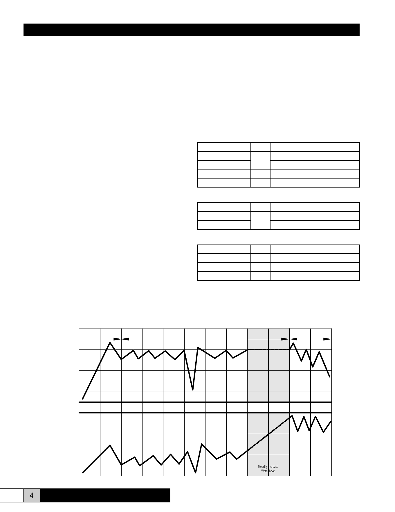
1. On initial start-up or a call for humidity, the humidier will
attempt to ll to its full load amp rating. The unit will not
necessarily have a full cylinder of water when capacity is
reached. Water level depends on the conductivity of the
water. The more conductive the water, the more current
that can be passed through and will result in a lower
water level during operation. If the water is not conductive
enough to allow the unit to reach full load amps (full
capacity) on the initial ll, the cylinder full module will
stop the ll valve until the water conductivity increases.
The unit will operate in this mode with repetitive ll
and boil cycles until the unit has concentrated enough
minerals in the water to reach the rated amp level. Once
full load amp (FLA) has been reached, the ll valve will
shut off. The unit will now compare the rate of change of
amp draw to a time cycle.
2. Once the water in the cylinder is mineral laden and hence
very conductive, a drain cycle will be initiated. Some or
all of the water in the cylinder will be drained to ush away
the minerals. After the drain cycle and/or the time cycle is
completed, the unit will rell and start the process over.
These cycles will repeat until:
• The call for humidity is satised.
• The cylinder is used up.
• A fault condition occurs.
3. Over a very long term, as the electrodes in the cylinder are
coated with minerals, the water level will slowly increase
to the cylinder full level. Concentration will no longer allow
the unit to reach FLA. The unit will eventually display an
“end of cylinder life” fault by blinking the LED on the front
of the unit at ½ second intervals. Replacement of the
cylinder is required at this point in order for the unit to
continue operating at its rated capacity.
What’s in the Box?
Complete Humidication System
Part No. Qty. Description
267460-003
1
CFS20 Unit
267460-004 CFS22 Unit
AH-297 1 Air Proving Switch
267947-002 1 Parts Bag*
Unit Only
Part No. Qty. Description
267460-005
1
CFS20 Unit
267460-006 CFS22 Unit
Accessory Kit
Part No. Qty. Description
AH-297 1 Air Proving Switch
EST-596 1 Steam Hose, 1” ID
EST-1550 1 Duct Steam Pipe Assembly
* Includes two lag screws (Part No. EST-1138), two ¾” - 1½” clamp hoses
(Part No. EST 1563), one 12” clear PVC vinyl tubing with 1” OD (Part No.
EST-206), and one stainless steel clamp hose (Part No. EST-207).
General Time of Operation
1. 2.
3.
High Drain
Threshold
Capacity
Set Point
Low Drain
Threshold
Cylinder
Full
Steadily Increase
Water Level
Water Level
Output
ComfortSTEAM
®
CFS20 & CFS22
Installation, Operation, & Maintenance Manual
5
www.trioniaq.com
Faults:
Overcurrent (Solid Light)
• 138% of Rated Current
• System Shutdown
Fill System (Slow Blink)
• Fill valve open for 24 minutes without achieving
capacity setpoint or cylinder full
• System Shutdown
End of Cylinder Life (Fast Blink)
• 24 hours of operation while on cylinder full without
achieving capacity setpoint.
• System Shutdown
• Operation using water of less than 125 micro-
Siemens is not recommended.
• Typically 500-2000 hours of cylinder operation can
be obtained. Your actual cylinder life may be higher
or lower depending on the exact composition of
your water supply.
Key Features
Adjustable Setpoints (See Figure 13, Page 13)
Capacity
• Range = 50-100%
• Preset at 100%
Low Drain Threshold
• Range = 50-100%
• Preset at 80%
Cycle Time
• Range = 30-180 seconds
• Preset at 60 seconds
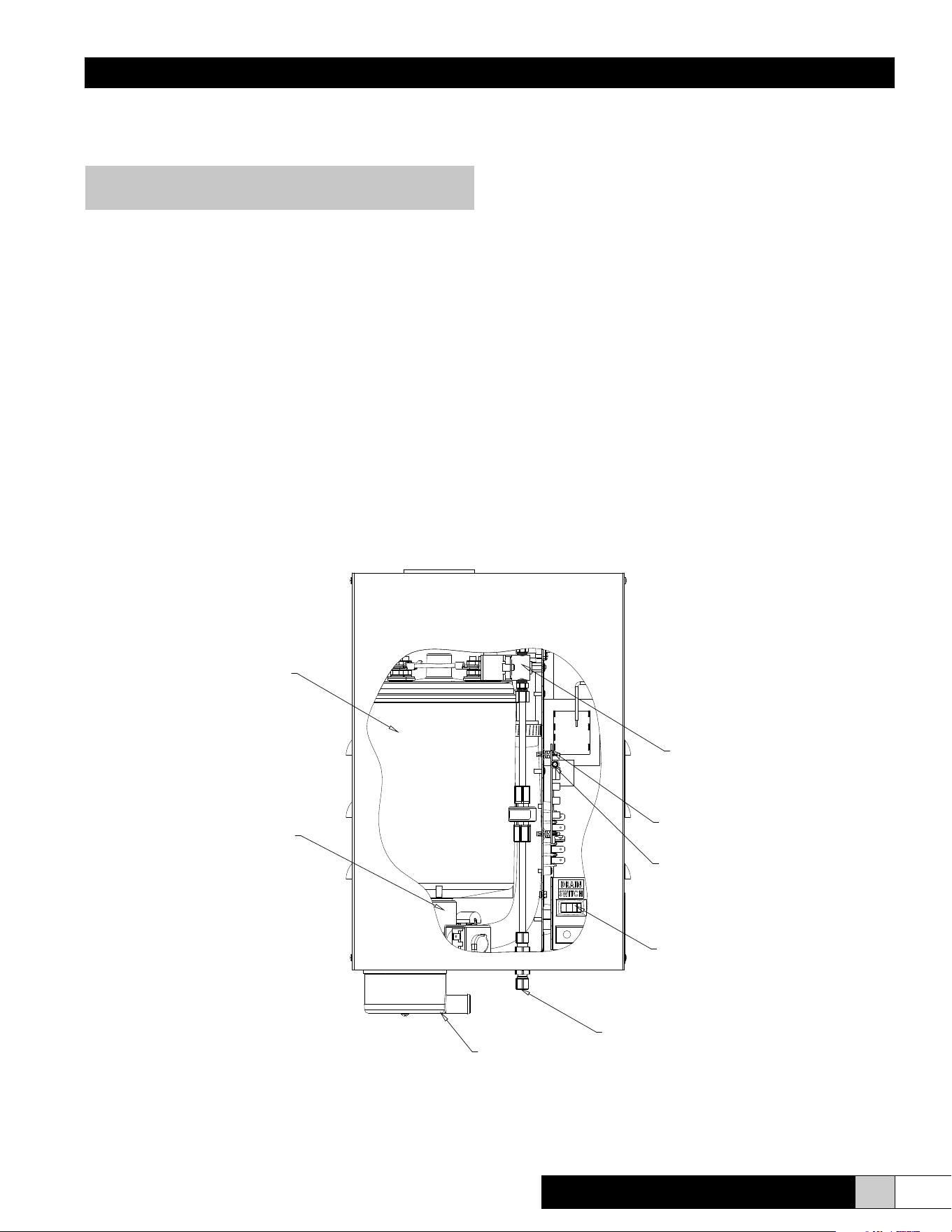
DRAIN
CONNECTION
DRAIN SWITCH
FAULT LIGHT
(VISIBLE THROUGH FRONT COVER)
CIRCUIT BOARD
FILL SYSTEM
(INTEGRAL 1" AIR GAP PREVENTS
REVERSE SIPHONING TO POTABLE
WATER SUPPLY; "ADJUSTABLE
METERING VALVE ACCOMODATES
WATER PRESSURES UP TO 100 PSI.")
CYLINDER - REPLACEABLE
GLASS FILLED POLYPROPYLENE
DRAIN SYSTEM
(DRAIN VALVE, ADJUSTABLE
DRAIN THRESHOLD AND CYCLE
TIME PROVIDE EXTENDED LIFE.)
FILL CONNECTION
Figure 1
ComfortSTEAM
®
CFS20 & CFS22
NOTE: These setpoints should be adjusted by a
qualied service person only.
Installation, Operation, & Maintenance Manual
6 www.trioniaq.com
NOTE: The steam distributor pipe is inherently sloped to
return the condensate to the humidier.
An airow proving switch is provided for a better system control.
If the heating system operates for short periods at a time and the
desired relative humidity level is not achieved, the humidier can
be wired to turn on the blower when there is a call for humidity.
(See Figures 8-9, page 9.)
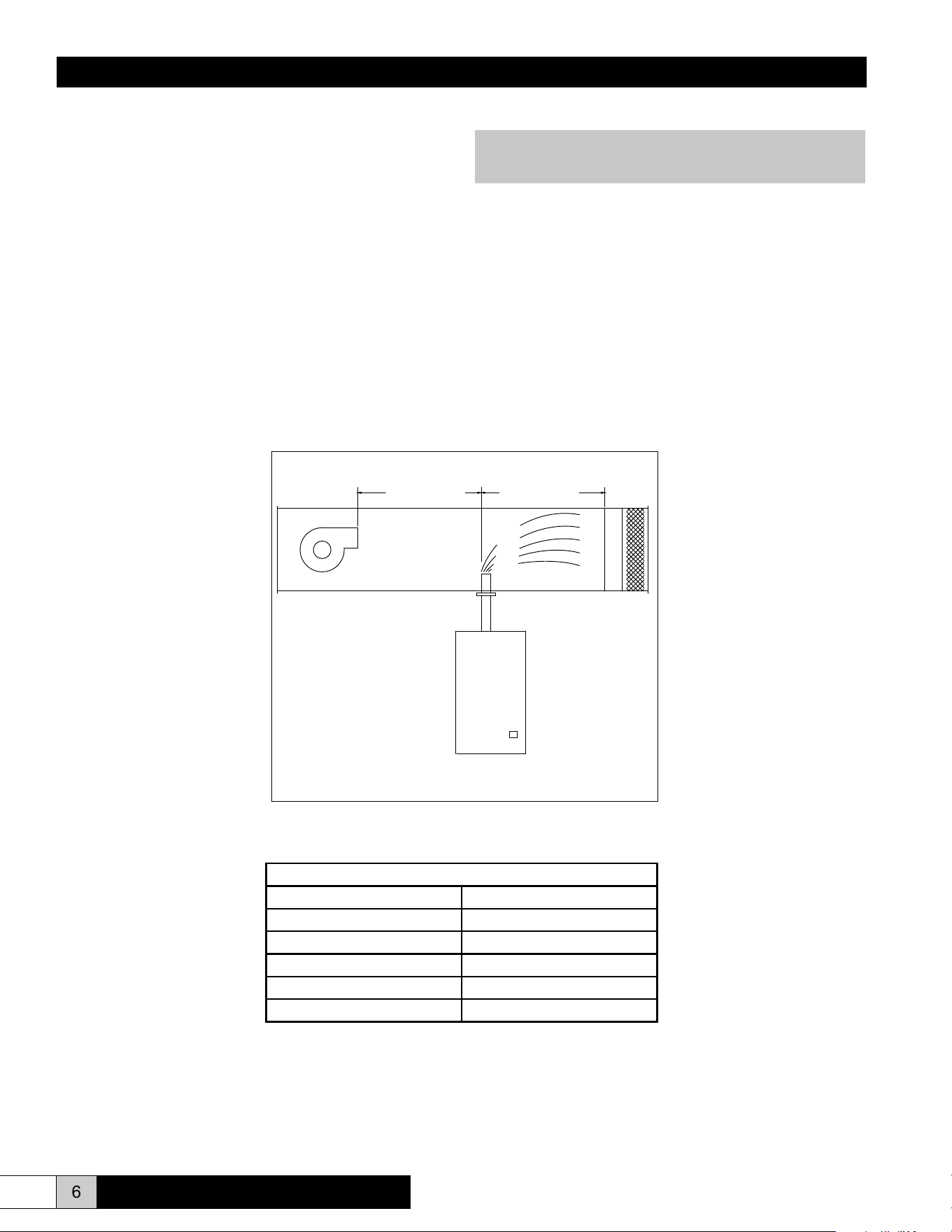
Engineering and Application
The CFS20/22 series steam humidiers can be applied in a
variety of applications. The simplest application is to utilize
the steam generated by the CFS unit to discharge it directly
into the HVAC system ductwork. In this application, a steam
pipe is preferably installed in the system ductwork at least 5
feet downstream of the supply air blower. There should be no
obstructions within the rst 5 feet downstream of the steam
distributor as shown in Figure 2. A minimum duct temperature
of 60° F is recommended. Different psychrometric conditions
may require greater or lesser steam absorption distances.
Temperatures below 60°F may cause condensation to form in
the duct. External lined duct may be used if the thickness is 1”
or less.
Note: Duct liner may be used
with a maximum
thickness of 1".
5 FEET MINIMUM
5 FEET MINIMUM
18 INCHES
MINIMUM
5 FEET MINIMUM
Figure 2
Allowable Operating Conditions
Ambient Temperature 40°F (4°C) to 120°F (50°C)
Ambient Relative Humidity 0% to 90% (non-condensing)
Line Voltage -15% to +10% of normal
Frequency 50/60 Hz
Water Supply Pressure 20psi - 100psi
Maximum Duct Static Pressure 1”
ComfortSTEAM
®
CFS20 & CFS22
Installation, Operation, & Maintenance Manual
7
www.trioniaq.com
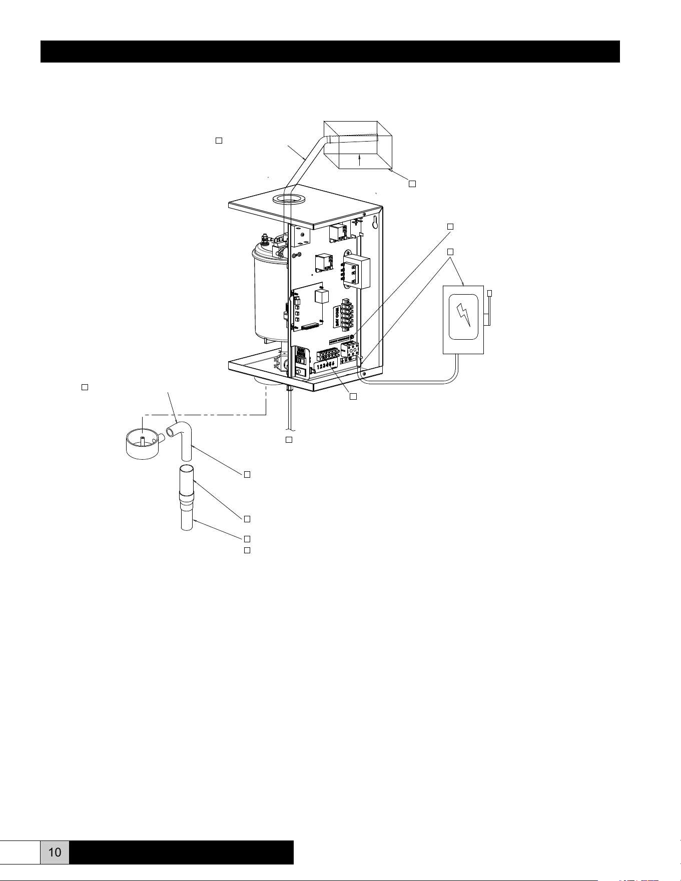
Plumbing
To make the necessary connections for water ll and drain, the
following steps are required. (Refer to Figure 4 for locations.)
1. Install external shutoff valve between the water supply and
the humidier for ease in servicing the unit.
2. Connect water supply to the 1/4” compression tting on the
bottom of the cabinet.
3. Connect the 3/4” tube from the accessory pack to the drain
reservoir. Cut the tube to the length necessary to reach the
drain.
4. Insert the other end of the tube into a minimum 6” vertical
length of the 1-1/4” minimum I.D. drain line. The balance of
the drain line should be 1” I.D. minimum with a minimum
1/8” per foot slope. (See Figure 4.)
SECTION III INSTALLATION INSTRUCTIONS
Mounting
The cabinet is designed to safely contain the working components
of the TRION CFS 20/22 series humidier and dissipate heat
to protect the electronics. Locate humidier, steam pipe and
accessories in a manner to allow routine inspection and any
necessary maintenance. DO NOT install the unit above false
ceilings or around valuable property, where a malfunction could
cause damage. Correct positioning of the humidier is important
to allow for proper operation and easy maintenance. Minimum
clearance around the cabinet should be maintained as follows:
Minimum Clearances
Around Cabinet
Left 6”
Right 12”
Top 6”
Bottom 12”
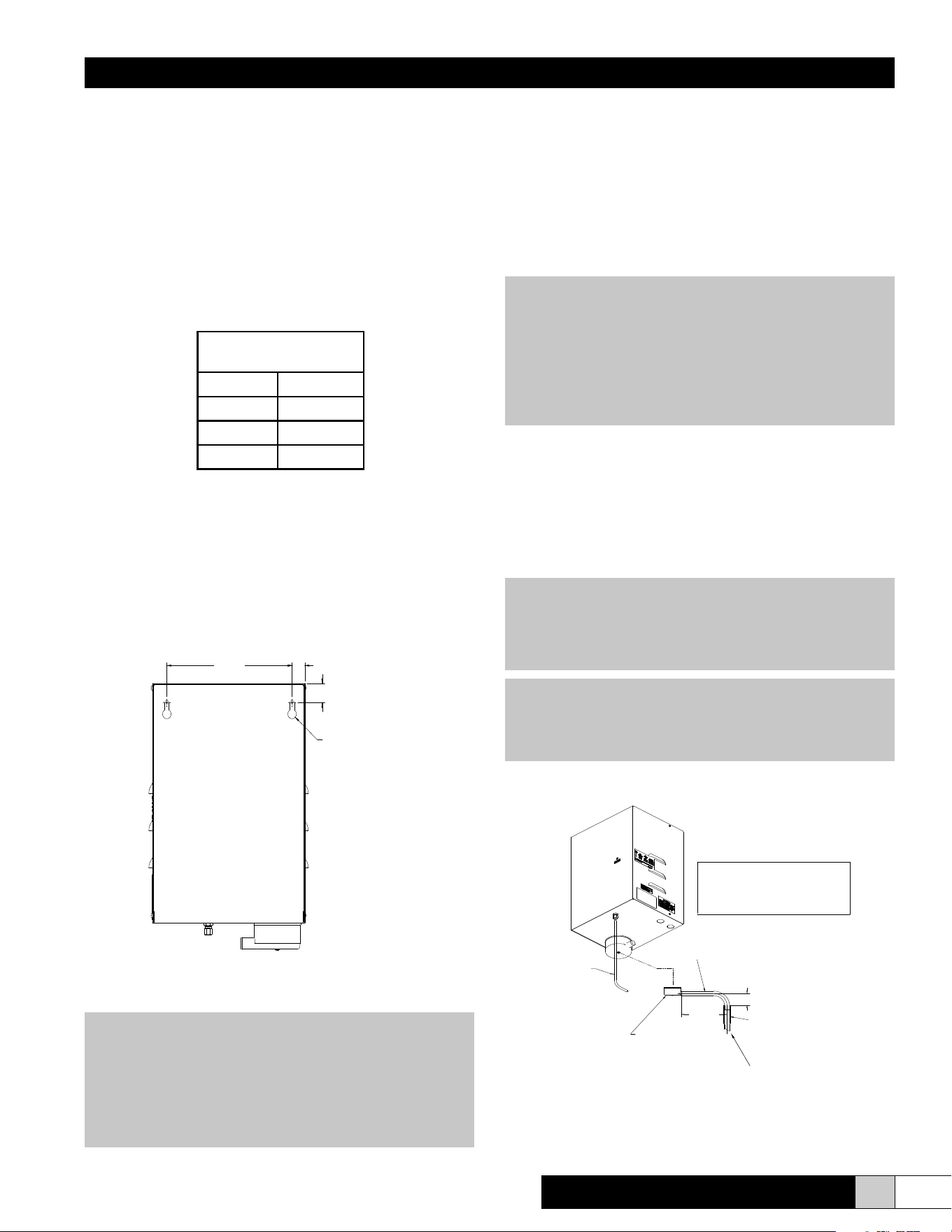
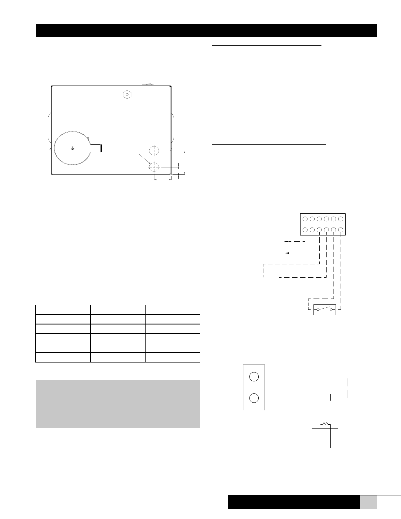
1. Remove cover by removing four side screws.
2. Remove foam packing from top of cylinder.
3. Two 5/16” lag bolts are supplied with the CFS20/22 unit.
Install the lag bolts according to the dimensions in Figure 3.
4. Hang the unit on the wall and secure the bolts. Be sure the
unit is level and mounted directly to the wall into wood studs
at least 2” thick (or equivalent). Operating weight is 27 lbs.
5. Replace cover and four screws.
Figure 3 (Back View)
WARNING!
Do not mount any controls inside the unit or tap power
from any location in the unit, except as stated in these
instructions. Do not place objects near the cabinet. Do
not attach to dry wall without studs. At least one of the
5/16” bolts must be located on a stud.
FIGURE #3
(BACK VIEW)
9.00
.91
1.31
Ø .625 X .313"
KEYHOLE MTG. SLOT
T Y P. 2
CAUTION!
Do not use reverse osmosis or demineralized water
treatment without rst consulting the factory. This
water may not be sufciently conductive to allow proper
operation. Consult factory if water is outside the range
of allowable conductivities (125-1250 micro-Siemens).
Do not use hot water.
WARNING!
If the drain line is exposed, it is recommended that it be
insulated for safety. Do not use PVC drain line unless
“Drain Tempering” is enabled.
NOTE: Inlet water pressure must be in the range of
20-100 psig. Consult the factory if you are outside this
range. Softened water may be used but requires that
the low drain threshold be adjusted.
ComfortSTEAM
®
CFS20 & CFS22
DRAIN LINE TO BE 1" MIN. I.D. TERMINATING
AT THE UNIT WITH 6" OF 1 1/4" I.D. VERTICAL
PLUMBING.
THIS ALLOWS AN AIR GAP BETWEEN THE 1" O.D.
DRAIN TUBE FROM THE UNIT AND THE DRAIN.
1/4" O.D. COPPER OR
POLY TUBE WATER FILL LINE
3/4" MIN. I.D./1" MAX O.D.
FLEXIBLE DRAIN CONNECTION
6" MIN. LENGTH OF 1-1/4" MIN. I.D.
COPPER LINE. IF PVC IS USED OR LOCAL
CODES REQUIRE A LOWER TEMPERATURE
BALANCE OF DRAIN LINE TO BE 1" MIN. I.D.
WITH A MINIMUM PITCH OF 1/8" PER 12" OF RUN
DRAIN RESEVOIR
DRAIN WATER, ENABLE DRAIN TEMPERING.
4" RECOMMENDED
8"
RECOMMENDED
Figure 4
Installation, Operation, & Maintenance Manual
8 www.trioniaq.com
Distributor Mounting Instructions
Sheetmetal Duct:
Make a 1-1/4” hole in the duct at desired location. Insert duct
distributor and secure with self tapping sheetmetal screws
(supplied by others).
Fiberboard Duct:
Make a 1-1/4” hole in the duct at desired location. Insert duct
distributor and mark the four holes on ange. Drill holes at
marked locations. Fasten distributor with bolts (supplied by
others).
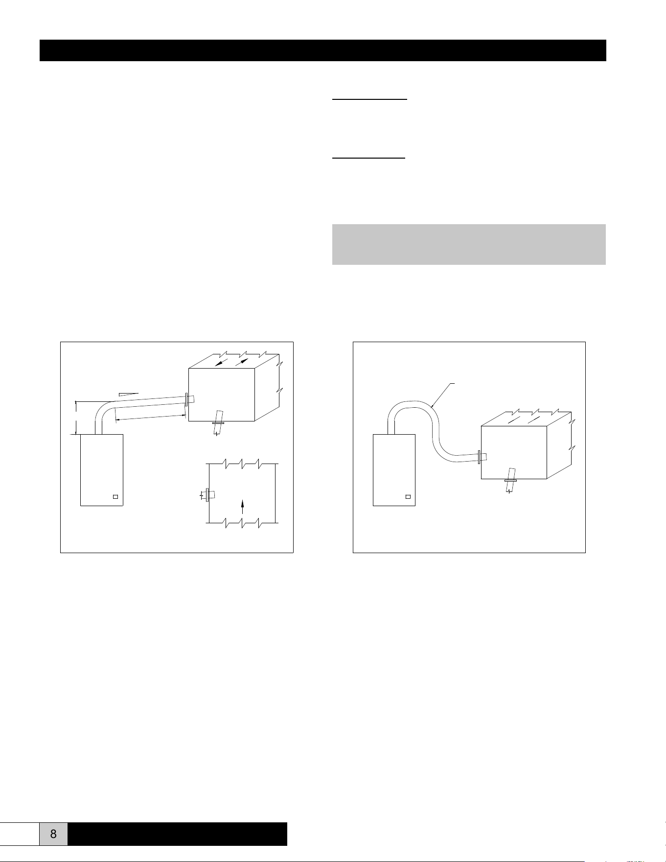
Steam Distribution
TRION supplies a stainless steel duct distributor for injecting
pure steam into the duct. This can be installed in the side
(recommended) or the bottom (alternate) of the duct. (See Figure
5.) When installing in the side of the ductwork, make sure the unit
is positioned to allow condensate to drain back down the steam
hose to the steam generator. The duct distributor pipe has a built-
in pitch to allow condensate to drain back into the hose. The hose
must be installed with a minimum 8% (1” per foot) pitch back to the
humidier to allow condensate to drain back to the steam cylinder.
(See Figure 5.) The steam hose may be used up to a maximum of
10 feet between the unit and the steam distributor. (Additional hose
may be required.) There can not be sags in the steam hose, as
this will create a trap and will produce back pressure in the steam
cylinder and may blow condensate in the duct. (See Figure 6.)
VERTICAL DUCT
HORIZONTAL DUCT
MIN. 8%
10.00 MIN.
(254 mm)
NO SAGS
ALLOWED
HORIZONTAL DUCT
INCORRECT
NO SAGS ALLOWED
Note: Internally lined duct should be removed in the
steam evaporation zone.
Figure 5 Figure 6
ComfortSTEAM
®
CFS20 & CFS22
Installation, Operation, & Maintenance Manual
9
www.trioniaq.com
If using a humidistat for automatic control:
1. If the humidistat needs to be powered by 24VAC, then
connect the humidistat power input to the humidistat 24VAC
power output located on terminal strip position #1 (24VAC
Hot) and position #2 (24VAC Common).
2. Connect the humidistat normally open contacts to the
humidifier as follows. Connect one of the humidistat
normally open contacts to the 24VAC Hot either from the
humidistat power connection or from the humidifier terminal
strip position #1. Connect the other humidistat normally
open contact to position #3 of the humidifier terminal strip.
Finally, connect the humidifier terminal strip position #2 to
humidifier terminal strip position #4.
If using just a basic switch for on/off control:
1.
Connect the first side of the switch to humidifier terminal
strip position #1.
2. Connect the other side of the switch to humidier terminal
strip position #3.
3. Finally, connect humidier terminal strip position #2 to
humidier terminal strip position #4.
Figure 8
Figure 9
4
3
2
1
AIR PROVING SWITCH
(INCLUDED)
CONTROL WIRING
5
6
24VAC OUTPUT FOR POWERING
EXTERNAL ELECTRONIC HUMIDISTAT*
24V HOT
24V COM.
* IMPORTANT: LEAVE THESE TERMINALS OPEN IF
NOT USING ELECTRONIC HUMIDISTAT
.
C
ONNECTION OF THESE TERMINALS AS ANOTHER
POWER SOURCE MAY DAMAGE THE UNIT.
24VAC
SIGNAL
Wiring
All eld wiring should be routed up through the holes in the
bottom panel or in the back of the unit.
Figure 7 (Bottom View)
Supply Power
1. Ensure that minimum circuit amperage capacity is 15 amps.
2. Terminals are provided in the electrical compartment for
eld connection of the main power supply legs (single
phase) and a ground wire.
3. Install external overcurrent protection and provide wiring in
accordance with the NEC, state and local codes.
4. Power supply must be “clean”: free of spikes, surges and
sags: -15% to +10% of nominal.
Electrical Characteristics:
Model CFS20 CFS22
lbs/hr 4 8
kg/hr 1.8 3.6
Voltage 115 230
Amps 11.5 11.5
kW 1.33 2.66
Control Circuit Connections
WARNING!
Do NOT install any controls inside the TRION CFS 20/22
cabinet. Installations of any extraneous devices inside
the electrical compartment may cause erratic behavior of
the circuitry and will VOID the warranty.
The humidier is turned on by applying 24VAC across positions
#3 and #4 of the terminal strip shown in Figure 8. The two most
common ways to control the humidier are to use a humidistat
for automatic operations or to use just a basic switch to
permanently turn on or turn off the unit.
BOTTOM VIEW
1.56
.75
Ø.88 THRU HOLE
2.37
ComfortSTEAM
®
CFS20 & CFS22
G
R
THERMOSTAT
TERMINALS
267575-001
AUXILARY RELAY
INSIDE CABINET
ComfortSTEAM
®
CFS20 & CFS22
Installation, Operation, & Maintenance Manual
10 www.trioniaq.com
Installation Checklist
NOTE:
The TRION CFS20/22 Humidier checklist is provided to help the installer ensure a successful installation. If further
assistance is needed from the TRION representative or the factory, the checklist is expected to be completed. If a job
site visit is required from the TRION representative or the factory, and the checklist has not been accurately completed,
additional charges may be applied by the individual(s) representing TRION. If the visit uncovers a component malfunction,
the parts will be replaced under warranty.
_____________________________________________ ____________________________________________
Project Name Checklist completed by
_____________________________________________ ____________________________________________
Humidier Installer (Company) Checklist completion date
DRAIN RESERVOIR
BALANCE OF DRAIN LINE TO BE 1" MIN. I.D.
DRAIN WATER TEMPERATURE IS SUITABLE FOR PLUMBING.
3/4" MIN. I.D./ 1" MAX. O.D.
FLEXIBLE DRAIN CONNECTION
6" MIN. LENGTH OF 1 1/4" MIN. I.D. VERTICAL COPPER LINE.
IF PVC IS USED, ADD DRAIN TEMPERING.
DURING FILL CYCLE, CHECK TO SEE IF ANY WATER
IS DRAINING FROM UNIT. A LOT OF WATER FLOWING
OUT OF THE UNIT WOULD INDICATE EXCESSIVE
WATER PRESSURE. TURN OFF POWER AND REDUCE
THROUGH METERING FILL SOLENOID OR SUPPLY
VALVE TO HUMIDIFIER. A SMALL AMOUNT OF WATER
IS NOT UNCOMMON.
MAKE SURE ALL HIGH VOLTAGE
ELECTRICAL CONNECTIONS
ARE TIGHT, 15-20 IN-LBS.
POWER SUPPLY:
1. MATCHES DATA PLATE
2. IS PROPERLY GROUNDED
3. CAN CARRY AT LEAST 15 AMPS
4. EXTERNAL FUSED DISCONNECT
PROVIDED BY OTHERS.
SUPPLY WATER (POTABLE)
NO UNTRAPPED LOW SPOT
IN STEAM SUPPLY
AIR FLOW IS HORIZONTAL OR VERTICAL
LOW VOLTAGE TERMINAL STRIP:
1. 24VAC SIGNAL (FROM HUMIDISTAT)
2. AIR PROVING SWITCH
3. 24VAC CONNECTION TO HUMIDISTAT (IF REQ'D)
Figure 10
ComfortSTEAM
®
CFS20 & CFS22
Installation, Operation, & Maintenance Manual
11
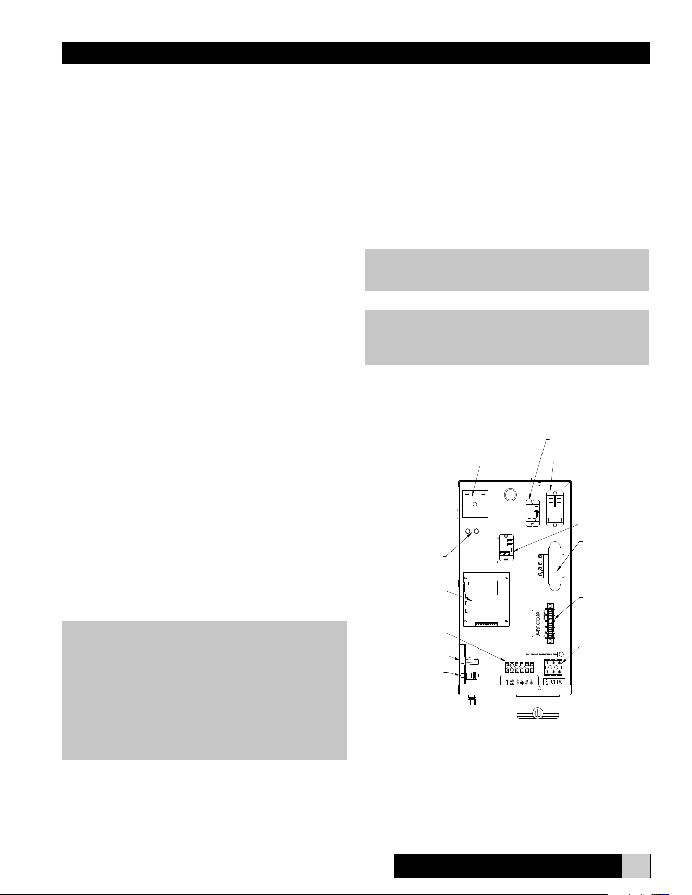
www.trioniaq.com
CYLINDER FULL
INTERFACE
ELECTRODE
RELAY
FILL VALVE
ADJUSTING SCREW
POWER
TERMINAL BLOCK
TRANSFORMER
24VAC COM
TERMINAL BLOCK
TERMINAL
STRIP
MAIN CIRCUIT
BOARD
AUXILIARY
RELAY
DRAIN SWITCH
COVER INTERLOCK
SWITCH
24VAC SIGNAL RELAY
NOTE: If upon initial start-up of this humidier the
cylinder is slow in heating and/or the service light
continues to come on, drain the tank to 1/4 full. Turn off
power at disconnect, obtain some Alka-Seltzer tablets
and crumble 1/2 of one tablet (Alka-Seltzer) into the grey
ll tee. Then turn the disconnect on and run the unit. If
you have had to use this step on a 230V unit (CFS22),
it is advisable that you order a 268613-001 replacement
cylinder rather than the standard replacement cylinder in
the future so this procedure will not need to be repeated.
SECTION IV OPERATING INSTRUCTIONS
Often in residential control environments and some other control
system designs, the humidier is controlled independently and
may not be interlocked with the air blower control system. In
these cases, the humidier is equipped with an auxiliary relay (as
shown in Figure 11). The auxiliary relay has one set of normally
open contacts that can be used to control the air blower system.
Those same normally open auxiliary relay contacts close when
the humider is powered on and generating steam.
If required, the auxiliary relay’s normally open contacts can
be wired as needed to interlock the humidier turn-on to the
subsequently turn on the air blower system. See Figure 9 for a
basic circuit diagram of the interlock connection of the auxiliary
relay contacts to the red and green wires of a typical residential
thermostat. Figure 9 is a very basic diagram and is for reference
only. The auxilary contact connection and control system
interlock design should be designed and wired by a control
engineer or by a licensed HVAC installer.
Start-up Instructions
1. Check that the humidier is properly mounted and level.
2. Check that the water ll and drain are properly connected.
3. Check that the correct voltage and amperage service are
supplied.
4. Check that all controls are wired properly.
5. Check that the steam distributor is properly installed and
that the steam hose has been properly routed without any
kinks or at spots.
6. With power OFF, double check all electrical connections
and plumbing connections to ensure that they did not
loosen during shipment.
7. With the control humidistat at the lowest setting, turn on the
main disconnect. The contactor should remain deenergized.
8. Turn the control humidistat up to the highest setting. The
relay should energize.
9. After approximately a ve-second delay, the ll valve
energizes and water begins to ll the cylinder to the preset
amp level or cylinder full condition, depending on the
incoming water supply. When starting up the unit, it is best
to put an amp clamp on the power leg that passes through
the toroid transformer. Ensure that the humidier lls
Figure 11 (View in from Right Side of Unit)
to “cylinder full” (approximately 1.5” from the top of the
cylinder), or that the amperage reaches the data label
maximum and the ll valve de-energizes.
10. All units are equipped with a drain tempering feature which
mixes cold ll water with the hot drain water to protect drain
piping. Unit is factory set with drain tempering inactive.
To activate, move drain tempering jumper to ON
position from circuit board. (See Figure 13.) Depending
on your ll water pressure, some adjustment of the ll
metering valve may be necessary to ensure drain water of
less than 140°F. (See Figure 11.)
11. Reset control humidistat to the desired setting. Refer to
instructions supplied with humidistat.
NOTE: The capacity of the humidier can be adjusted
between 50% and 100% of the maximum level by adjusting
the Capacity Adjustment Pot on the main circuit board.
CAUTION!
Inadequate airow may allow humidity to collect in areas
causing condensation.
Installation, Operation, & Maintenance Manual
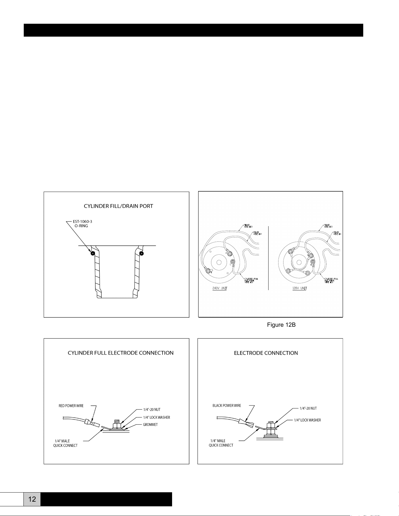
12 www.trioniaq.com
cylinder. Be sure that the o-ring is in place on the cylinder
ll/drain port prior to installation. (See Figure 12A.) New
o-ring is included with each replacement cylinder.
5. Clean and check both the ll and drain valves while servicing
the unit.
6. Install cylinder in unit by pushing downward with a slight
twisting motion, while ensuring proper orientation of cylinder
within cabinet.
7. Reconnect electrode power wires (#32 & #33) and cylinder
full electrode wire (#26). Make sure that all electrical
connections are securely tightened. (See Figures 12B,
12C, and 12D.) Replace cover and four screws.
8. Follow cold start-up instructions on page 11. Monitor amp
draw for several cycles.
Extended Shutdown
Always drain cylinder completely if unit will be off for an extended
period of time. This will preserve the life of the cylinder.
Figure 12B
Figure 12D
CYLINDER FULL
ELECTRODE
WIRE #26
POWER
WIRE #33
POWER
WIRE #32
120V UNIT
CYLINDER FULL
ELECTRODE
WIRE #26
POWER
WIRE #33
POWER
WIRE #32
240V UNIT
A
C
E
D
E
C
Maintenance
To maintain output, the water level in the cylinder will slowly move
upwards, exposing new electrode to the water as the electrodes
become coated with minerals. Eventually, all of the usable electrode
surfaces will be coated and the cylinder will be full of water. At this
point, the output capacity will begin to drop and the red “fault” light
will come on (fast blink). The unit will shut down. This indicates
the need to change the cylinder, typically after 500-2000 hours of
operation, depending on the quality of the ll water supply.
To Replace the Cylinder
1. Remove cover and four screws while being careful of wiring.
Drain cylinder completely using the drain switch.
2. Turn off power to the unit at the external disconnect.
Disconnect electrode power wires (#32 & #33) and cylinder
full electrode wire (#26) from the cylinder. These connections
are 1/4” quick connects. (See Figures 12B, 12C, and 12D.)
3. Disconnect 1” hose at top of cylinder.
4. Remove cylinder, clean out the drain cup and insert the new
Figure 12A
Figure 12C
ComfortSTEAM
®
CFS20 & CFS22
Installation, Operation, & Maintenance Manual
13
www.trioniaq.com
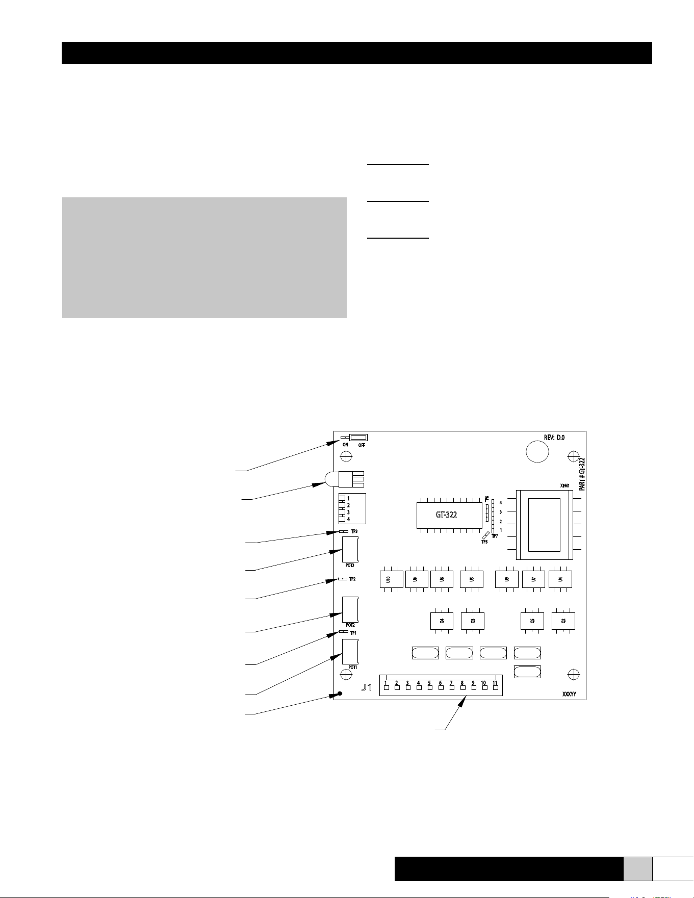
Test Points
Each circuit board (see Figure 13) features three test points to
aid in the troubleshooting process. Each of these test points
works on a 0-5 VDC scale. “0 VDC” = 0%. “5 VDC” = 100%. All
readings are between the test point and ground.
Test Point #1:
Provides exact reading of Time Cycle setting.
30-180% = 0-5 VDC (Factory set: 1 volt)
Test Point #2:
Provides exact reading of Low Drain threshold.
50-100% = 0-5 VDC (Factory set: 3 volts)
Test Point #3:
Provides maximum percentage of output.
50-100% = 0-5 VDC (Factory set: 5 volts)
SECTION V TROUBLESHOOTING GUIDE
All TRION CFS 20/22 series humidiers are manufactured under
strict quality control and are subjected to a complete operational
test prior to shipment. All circuit board adjustments are made at
the factory and should not be adjusted beyond the guidelines
set in this troubleshooting guide without rst consulting a factory
representative. The following information is for your help and
reference. If you still experience difculty after trying these
remedies, contact your TRION representative.
WARNING!
The TRION CFS20/22 series electronic steam humidier
cabinet was designed to house and shield the
components from outside interference. Absolutely
NO other components may be mounted inside or be
electrically tapped into the humidier without TRION’s
express written permission. Failure to heed this warning
will void your warranty.
Figure 13
FAULT LED
CAPACITY ADJUSTMENT POT
LOW DRAIN
THRESHOLD POT
TIME CYCLE POT
DRAIN TEMPERING
JUMPER
TEST POINT #1
(TIME CYCLE)
TEST POINT #2
(LOW DRAIN THRESHOLD)
TEST POINT #3
(CAPACITY ADJUSTMENT)
J1 CONNECTOR
GROUND
ComfortSTEAM
®
CFS20 & CFS22
Installation, Operation, & Maintenance Manual
14 www.trioniaq.com
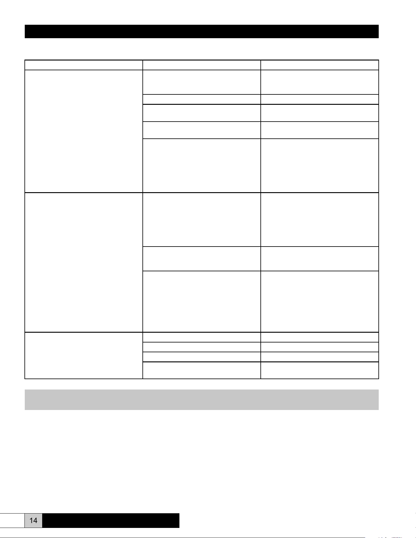
Unit Detected Faults (Red Service Light is ON)
Problem / Symptom Probable Cause Reason - Correction
Overcurrent (Solid Light)
The alarm condition occurs when an
overcurrent situation (>138% of rated
current) has occurred and the humidier
has shut down to prevent any damage.
This alarm indicates that there has been
a signicant reduction in resistance
between the main legs of the supply
power and the humidier has been shut
down to prevent damage and should be
serviced before it is restarted. Fault LED
R33 will be illuminated (solid - no ash).
Dead short between electrodes. Replace the steam cylinder. Check
resistance between electrodes with power
OFF.
Restricted or blocked drain. Clean and inspect drain system.
Restricted ll system. Clean and inspect the ll system. Check
for restriction or loss of supply pressure.
Incoming water conductivity is outside the
range of normal circuit board settings.
Consult the factory for options.
Check amp draw to unit during start-up.
If amp draw greatly exceeds rated amp
draw, the drain threshold pot, labeled “Low
Drain Threshold Pot”, must be increased
2% to increase the frequency and duration
of drains to reduce the conductivity inside
the cylinder.
Manually drain the unit and restart.
End of Cylinder (Fast Blink)
This alarm condition occurs if the
humidier is unable to reach full output
over a 24 hour timeframe. It is constantly
switching between “ll” and “cylinder full”
modes. This alarm indicates a need to
change the cylinder, that the water supply
is low in conductivity, or that a foaming
condition exists.
End of cylinder life – Cylinder life is
typically between 500 and 2000 hours,
depending on incoming water supply.
For emergency use, you may restart the
humidier with the Capacity Adjustment
Pot at a lower level to allow operation
until a replacement steam cylinder can
be obtained. To clear the fault, turn the
main disconnect to the unit “off” and then
back ON.
If incoming water supply is less than 125
micromho, the unit may not be able to
pass the rated current through the water.
See NON-FAULT ACTIVATED
PROBLEMS GUIDE – “Unit lls to the
cylinder full condition and remains cold.”
Foaming condition exists. Flush and ll the steam cylinder several
times and restart. If it persists, you must
lter or treat the water to remove the
foaming agent. See circuit board settings
on previous page if supply water is
softened. See NON-FAULT ACTIVATED
PROBLEMS GUIDE – “Water foaming
inside the cylinder.”
Fill System Fault (Slow Blink)
This alarm condition occurs when the ll
valve has been energized for a 24 minute
timeframe. The humidier has been shut
down to prevent any damage.
Loss of or restricted water supply. Check ll system.
Leaking drain system. Check drain system.
Defective drain valve. Repair and replace as required.
Defective ll valve. Repair and replace as required.
NOTE: The three fault conditions outlined above will cause the humidier to shut down and the fault light on the front of
the unit to illuminate. To clear these faults, the main power must be turned OFF and back ON again.
ComfortSTEAM
®
CFS20 & CFS22
Installation, Operation, & Maintenance Manual
15
www.trioniaq.com
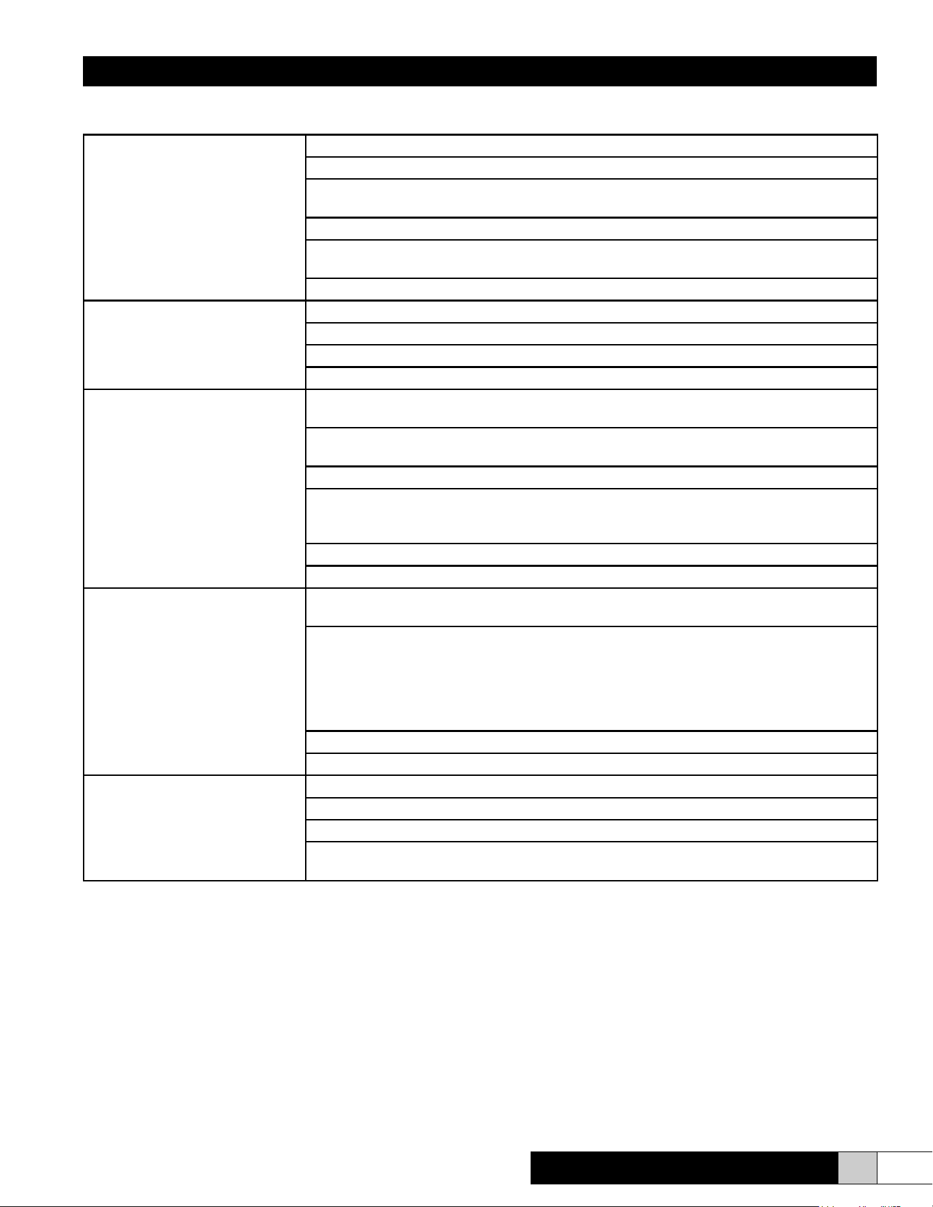
Non-Fault Activated Problems
Humidier turned ON but will not
operate
Check power supply.
Check circuit breaker.
Check connector J1 on the circuit board and ensure that it is plugged into the circuit board
properly and that no wires are loose.
Ensure that there is 24 VAC between pole #9 and #11 connector J1. If not, check wiring.
Place jumper between controls wiring terminal strip #3 and #4. If unit operates, check controls
settings and wiring (control, humidistat.)
Check door interlock.
Unit turned ON. Contactor pulled
in, but no water is entering the
cylinder.
Check external shutoff valves and open if closed.
Check strainer and ll valve for clogs. Turn adjusting screw.
Check ll valve coil to determine if it is receiving 24 VAC. If so, replace the valve.
Check for break in wiring.
Excessive arcing in cylinder Check drain valve and ensure that when it activates it drains freely. Clean if necessary.
Replace valve if defective.
Check water supply. If it is softened, increase the Low Drain Threshold Pot (POT 2) up to
XX%. (See Figure 13.)
Use high conductivity settings if water supply is very hard, >750 micromho.
Unit lling slower or at the same rate as the water is boiling, causing over concentration and
foaming. Check restriction in ll line. Adjust the metering ll valve to allow greater ow of
water. (See Figure 11.)
Have water analyzed. If iron content is greater than .1 mg/liter, a lter will have to be used.
Consult factory with water analysis.
Unit lls to the cylinder full condition
and remains cold
Check between Test Point #3 and ground with a multimeter set on VDC scale. Conrm the
circuit board is seeing low current ow (<3.5 VDC). Proceed to next step.
If on initial ll, unit reaches less than 70% of rated capacity (3.5 VDC on Test Point #3), adjust
the drain threshold pot, POT 2, down 2-3%. Manually drain the unit down completely and add
½ Alka Seltzer tablet via the ll tee (GT-120). Restart the unit while monitoring the amp draw.
Fill unit ¼ full and turn “off” for several minutes to allow tablets to dissolve. Restart unit. If
amperage rises rapidly, it may be necessary to dilute the water. If amperage rises slowly, add
another Alka-Seltzer tablet.
Check that drain valve is sealing properly.
Check the water conductivity and consult the factory.
Unit turned ON and cycles for a
short period of time. Then it stops
in the middle of a ll cycle and will
not reset until boiling stops.
Check cylinder ll interface connections.
Check cylinder connections. (See Figure 12B.)
Check items in next troubleshooting tip concerning foaming.
Check amperage between cylinder full electrode and cylinder full interface terminal #1. If it is
greater than 7.0 mA AC, take a ll water sample and consult the factory.
ComfortSTEAM
®
CFS20 & CFS22
Installation, Operation, & Maintenance Manual
16 www.trioniaq.com
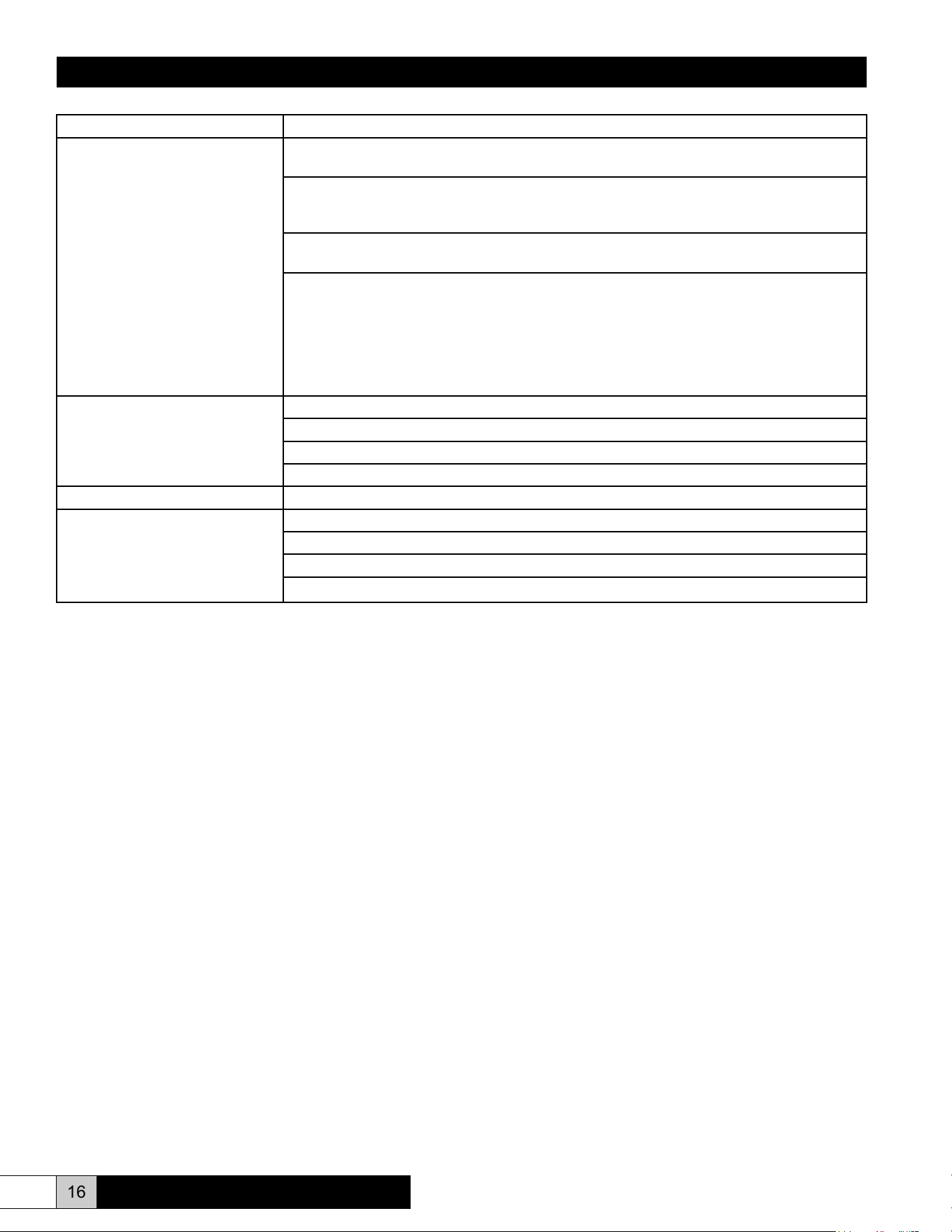
Problem/Symptom Reason - Correction
Water “foaming” inside the cylinder Check drain valve and ensure that water drains freely. If necessary, clean or replace valve if
defective.
Check water supply. If it is commercially softened, either increase the drain threshold (Test
Point #2) to 85% or reconnect the unit to raw water. Drain and restart the unit. If the unit is
connected to a hot water line, reconnect to the cold water line.
If steam line is hard copper, drain cylinder and test unit operation disconnected from steam
line to ensure ux from solder joints is not causing foaming.
Observe the ll tee (GT-120). If water is going down the overow and the water level is low:
• Check to ensure that static pressure in the duct is not forcing water down the overow
instead of allowing water to enter the cylinder.
• Adjust the ll metering valve to regulate the water ow to the cylinder. (See Figure 11.)
• Unit lling slower or at the same rate as it is boiling off, causing over concentration and
foaming. Fill rate must be increased. Open metering valve.
• If the ll valve is already fully open, get a water analysis and consult the factory.
Cylinder lls and overows Check cylinder wiring (See Figure 12.)
Check wiring of cylinder full interface.
Replace the circuit board.
Consult the factory after obtaining a water analysis.
Unit cycle ON and OFF rapidly Check location and setting of humidistat.
Cabinet leaks Check for loose connections.
Fill tube out of ll tee.
Steam cylinder out of drain cup.
Cabinet drain backing up, kink in drain line.
ComfortSTEAM
®
CFS20 & CFS22
Installation, Operation, & Maintenance Manual
17
www.trioniaq.com
ComfortSTEAM
®
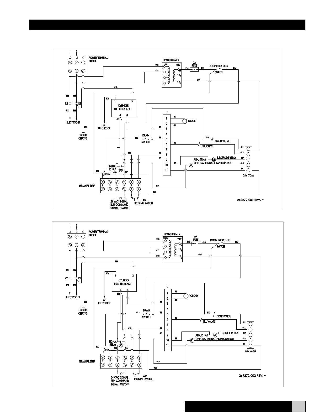
CFS20 & CFS22
CFS20 Wiring Diagram
CFS22 Wiring Diagram
Installation, Operation, & Maintenance Manual
18 www.trioniaq.com
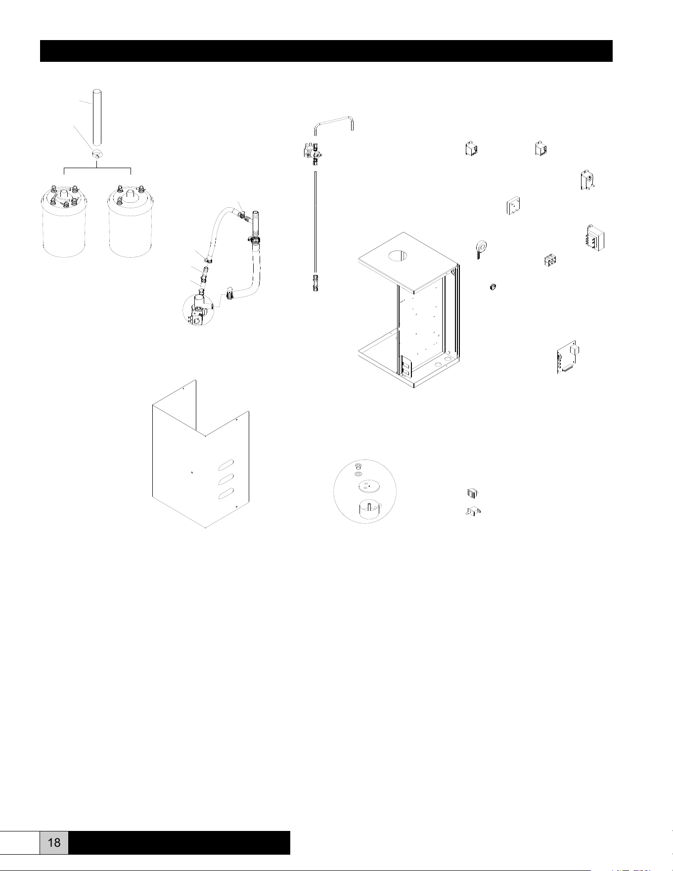
EST-1530
1845
FILL SUB-ASSEMBLY
138586-001
GT-120
EST-207
268612-001
DRAIN SUB-ASSEMBLY
1095
EST-1012
GT-262
EST-596
EST-207
EST-003A
GT-335
EST-1512
GT-322
EST-1225-KIT
EST-353
EST-105A
267575-001
GT-262
EST-1618
(CFS20)
268613-001
ASSEMBLY
CYLINDER
267640-001
4060
(CFS22)
268614-001
ASSEMBLY
CYLINDER
GT-196-KIT
267575-001
ComfortSTEAM
®
CFS20 & CFS22

Installation, Operation, & Maintenance Manual
Parts List
1095 Hose clamp SS
1845 Door interlock
4060 Fitting, 1/4” bulkhead
138586-001 Drain switch
267575-001 24VAC signal relay or auxilary relay
267640-001 Fill loop
268390-001 Power wire assembly replacement (not shown)
268612-001 Drain valve kit
268613-001 Steam cylinder assembly (115V units)
268614-001 Steam cylinder assembly (230V units)
EST-003A Cylinder full interface
EST-105A Toroid transformer
EST-207 Hose clamp SS
EST-353 Bushing, short 3/4” I.D.
EST-596 Steam hose
EST-1225-KIT Drain reservoir kit
EST-1512 Transformer, 115/230V to 24VAC
EST-1530 Terminal block
EST-1618 Tubing, 1” O.D. silicone
GT-120 Fill tee
GT-195-KIT Fill valve replacement kit
GT-262 Hose, 1/2” I.D. overow
GT-322 Main circuit board
GT-335 Electrode relay, 2 pole, 20A
19
www.trioniaq.com
ComfortSTEAM
®
CFS20 & CFS22

Form No. 267949-002 Rev. 12/17
TRION
®
101 McNeill Rd. | Sanford, NC 27330
P: 800.884.0002 | F: 800.458.2379 | www.trioniaq.com | [email protected]
© TRION 2017. All Rights Reserved.