
1
IMPORTANT SAFETY INFORMATION
We thank you for choosing our product. To ensure your safety and health, please use this
equipment correctly. It is impo
rtant to read this entire manual before assembling and using the
equipment. Safe and effective use can only be achieved
if the equipment is assembled,
maintained, and used properly. It is your responsibility to ensure that all users of the equipment
are informed of all warnings and precautions.
1. Before starting any exercise program, you should consult your physician to determine if you
have any medical or physical conditions that could put your health and safety at risk or
prevent you from using the equipment properly. Your physician’s advice is essential if you are
taking any medication that affects your heart rate, blood pressure, or cholesterol level.
2.
Be aware of your body’s signals. Incorrect or excessive exercise can damage your health.
Stop exercising if you experience any of the following symptoms: pain, tightness in your chest,
irregular heartbeat, shortness of breath, lightheadedness, dizziness, or feelings of nausea. If
you do experience any of these conditions, you should consult your physician before
continuing with your exercise program.
3.
Keep children and pets away from the equipment. The equipment is designed for adult use
only.
4.
Use the equipment on a solid, flat level surface with a protective cover for your floor or carpet.
To ensure safety, th
e equipment should have at least 2 feet (60 CM) of free space all around
it.
5. Ensure that all nuts and bolts are securely tightened before using the equipment. The safety
of the equipment can only be maintained if it is regularly examined for damage and/or wear
and tear.
6.
Always use the equipment as indicated. If you find any defective components while
assembling or checking the equipment, or if you hear any unusual noises coming from the
equipment during exercise, discontinue use of the equipment immediately and do not use until
the problem has been rectified.
7.
Wear suitable clothing while using the equipment. Avoid wearing loose clothing that may
become entangled in the equipment.
8. Do not place fingers or objects into the moving parts of the equipment.
9. The maximum weight capacity of this unit is 220 pounds (100KG).
10. The equipment is not suitable for therapeutic use.
11.
To avoid bodily injury and/or damage to the product or property, proper lifting and moving are
required.
12. Your product is intended for use in cool an
d dry conditions. You should avoid storage in
extreme cold, hot or damp areas as this may lead to corrosion and other related problems.
13.
This equipment is designed for indoor and home use only; it is not intended for commercial
use.
2
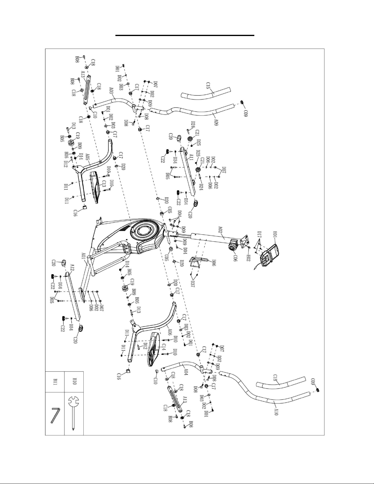
EXPLODED DIAGRAM 1
3
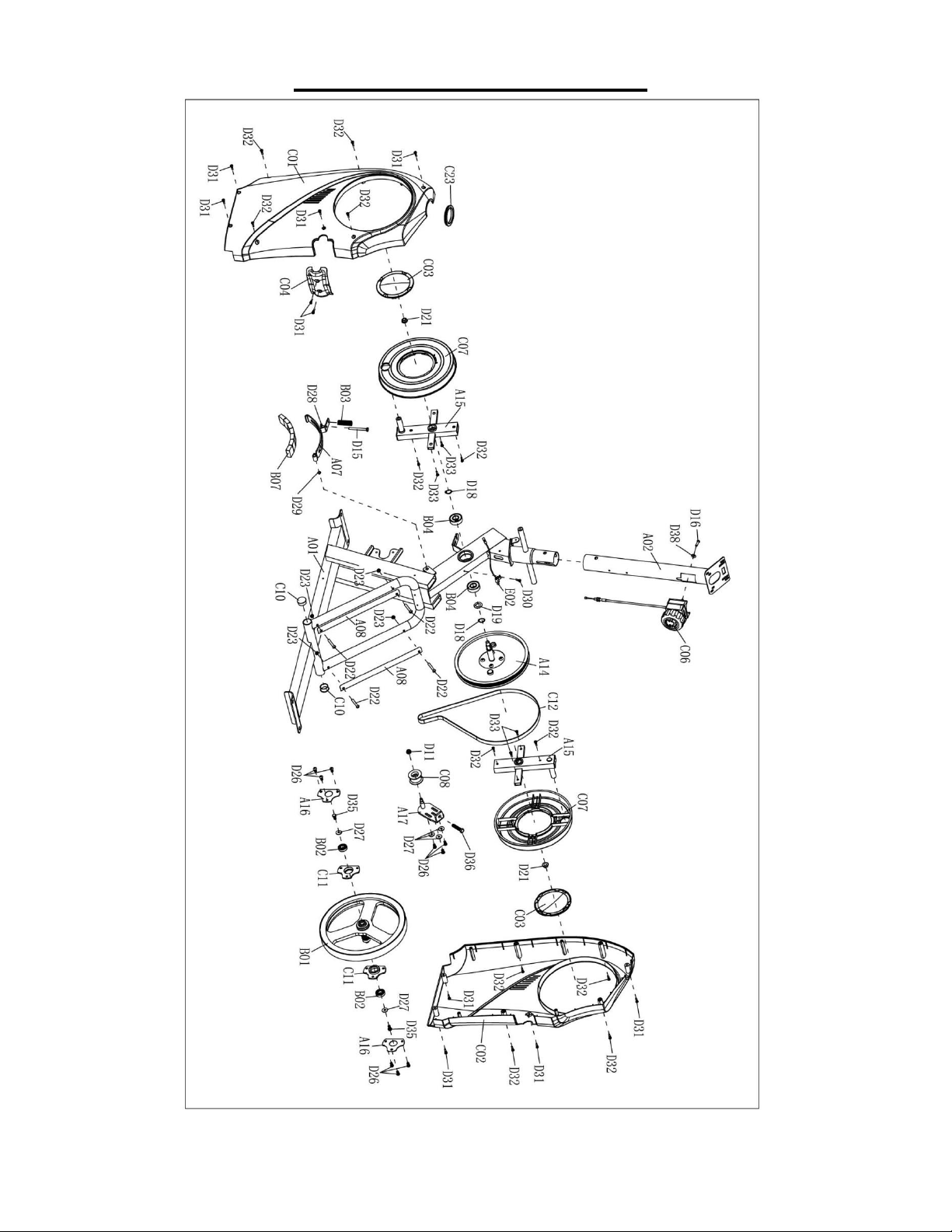
EXPLODED DIAGRAM 2

4
PARTS LIST
No.
Description
Spec.
Qty.
No.
Description
Spec.
Qty.
A01 Main Frame 1
C09 End Cap Ø32 2
A02 Upright Post 1
C10 End Cap Ø28 4
A03 Left Swing Rod 1
C11 Bearing Bracket 2
A04 Right Swing Rod 1
C12 Belt 1
A05 Left Pedal Tube 1
C13 Left Pedal 1
A06 Right Pedal Tube 1
C14 Right Pedal 1
A07 Magnetic Board 1
C15 Foam Grip 2
A08 Stainless Steel Plate 2
C16 End Cap 2
A09 Left Handlebar 1
C17 Bushing 8
A10 Right Handlebar 1
C18 Bushing 8
A11 Front Stabilizer 1
C19 Pulley 2
A12 Rear Stabilizer 1
C20 End Cap 4
A13 Connection Plate 2
C21
Transportation
Wheel
2
A14 Belt Wheel 1
C22 Foot Pad M8 4
A15 Rotary Support Frame 2
C23 Ring 1
A16 Fixed Disk δ1.5 2
D01 Bolt M8*20 4
A17 Idler Wheel Shaft 1
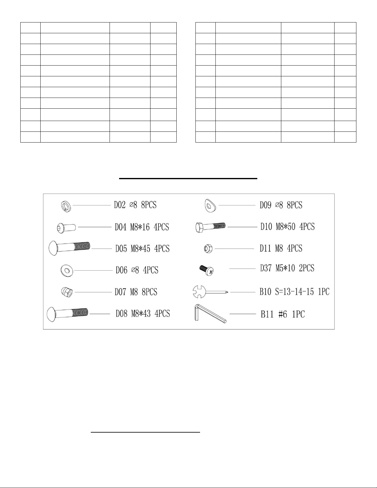
D02 Spring Washer Ø8 12
B01 Flywheel 4KG 1
D03 Flat Washer Ø24*D8*2 4
B02 Bearing 6001 2
D04 Bolt M8*16 4
B03 Tension Spring 1
D05 Bolt M8*45 4
B04 Bearing 6203 2
D06 Flat Washer Ø8 4
B05 Bearing 6000 4
D07 Acorn Nut M8 8
B06 Bottle Holder 1
D08 Bolt M8*43 4
B07 Magnet 30*25*12 7
D09 Arc Washer Ø8 8
B08 Bolt 4
D10 Bolt M8*50 4
B09 Sleeve 2
D11 Nut M8 5
B10 Spanner S=13-14-15 1
D12 Bolt M8*40 2
B11 Allen Wrench #6 1
D13 Bolt M10*50 2
C01 Left Belt Cover 1
D14 Nut M10 2
C02 Right Belt Cover 1
D15 Bolt M6*65 1
C03 Rotary Cover 2
D16 Bolt M5*20 1
C04 Cover 1
D17 Bolt M5*12 4
C05 Sleeve 2
D18 Spring Washer Ø17 2
C06 Tension Control Knob 1
D19 Wave Washer Ø21*Ø17.5*0.3 1
C07 Turntable 2
D20 Wave Washer Ø16*Ø26*0.3 4
C08 Idler Wheel 1
D21 Nut M10*1.25 2
5
HARDWARE PACKAGE
Ordering Replacement Parts (U.S. and Canadian Customers only)
Please provide the following information in order for us to accurately identify the part(s) needed:
The model number (found on cover of manual)
The product name (found on cover of manual)
The part number found on the “EXPLODED DIAGRAM” and “PARTS LIST” (found near the front of
the manual)
Please contact us at support@sunnyhealthfitness.com or 1- 877 - 90SUNNY (877-907-8669).
No.
Description
Spec.
Qty.
No.
Description
Spec.
Qty.
D22 Bolt M6*38 4
D32 Bolt ST4.2*16 12
D23 Nut M6 4
D33 Bolt ST4.2*10 4
D24 Bolt M8*40 2
D34 Nut M8 4
D25 Nut M8 2
D35 Bolt M6*16 2
D26 Bolt M6*12 9
D36 Bolt M8*45 1
D27 Flat Washer Ø6*Ø18*1.5 5
D37 Bolt M5*10 2
D28 Nut M6 1
D38 Arc Washer Ø5 1
D29 Spring Washer Ø8 1
E01 Computer 1
D30 Bolt ST4.2*12 1
E02 Sensor Wire
1
D31 Bolt ST4.2*16 10
6
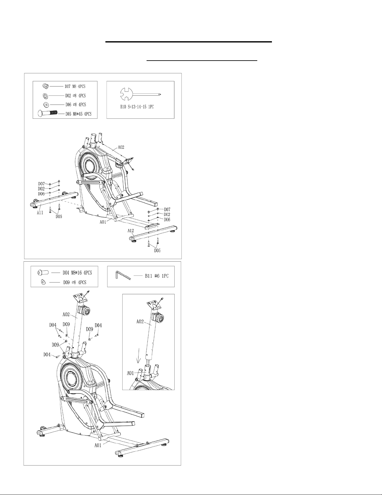
ASSEMBLY INSTRUCTIONS
We value your experience using Sunny Health and Fitness products. For assistance with parts or
troubleshooting, please contact us at support@sunnyhealthfitness.com or 1-877-90SUNNY (877-
907-8669).
STEP 1:
Attach the Front Stabilizer (No. A11) to
the Main Frame (No. A01), using 2 Bolts
(No. D05), 2 Flat Washers (No. D06), 2
Spring Washers (No. D02) and 2 Acorn
Nuts (No. D07). Tighten and secure with
Spanner (No. B10).
Attach the Rear Stabilizer (No. A12) to the
Main Frame (No. A01), using 2 Bolts (No.
D05), 2 Flat Washers (No. D06), 2 Spring
Washers (No. D02) and
2 Acorn Nuts
(No. D07). Tighten and secure with
Spanner (No. B10).
STEP 2:
Attach the Upright Post (No. A02) to the
Main Frame (No. A01), using 4 Bolts (No.
D04) and 4 Arc Washers (No. D09).
Tighten and secure with Allen Wrench (No.
B11).
Note: Please be careful not to clip the wires.
7
We value your experience using Sunny Health and Fitness products. For assistance with parts or
troubleshooting, please contact us at support@sunnyhealthfitness.com or 1-877-90SUNNY (877-
907-8669).
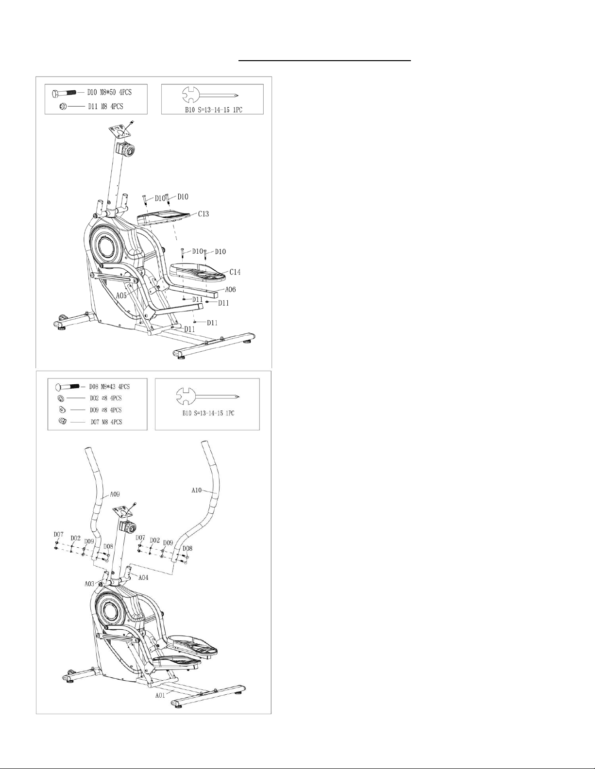
STEP 3:
Attach the Left Pedal (No. C13) to the Left
Pedal Tube (No. A05), using 2 Bolts (No.
D10) and 2 Nuts (No. D11). Tighten and
secure with Spanner (No. B10).
Attach the Right Pedal (No. C14) to the
Right Pedal Tube (No. A06), using 2 Bolts
(No. D10) and 2 Nuts (No. D11). Tighten
and secure with Spanner (No. B10).
STEP 4:
Attach Left Handlebar (No. A09) to the Left
Swing Rod (No. A03) using 2 Bolts (No.
D08), 2 Arc Washers (No. D09), 2 Spring
Washers (No. D02) and 2 Acorn Nuts (No.
D07). Tighten and secure with Spanner
(No. B10).
Attach Right Handlebar (No. A10) to the
Right Swing Rod (No. A04) using 2 Bolts
(No. D08), 2 Arc Washers (No. D09), 2
Spring Washers (No. D02) and 2 Acorn
Nuts (No. D07). Tighten and secure with
Spanner (No. B10).
8
We value your experience using Sunny Health and Fitness products. For assistance with parts or
troubleshooting, please contact us at support@sunnyhealthfitness.com or 1-877-90SUNNY (877-
907-8669).
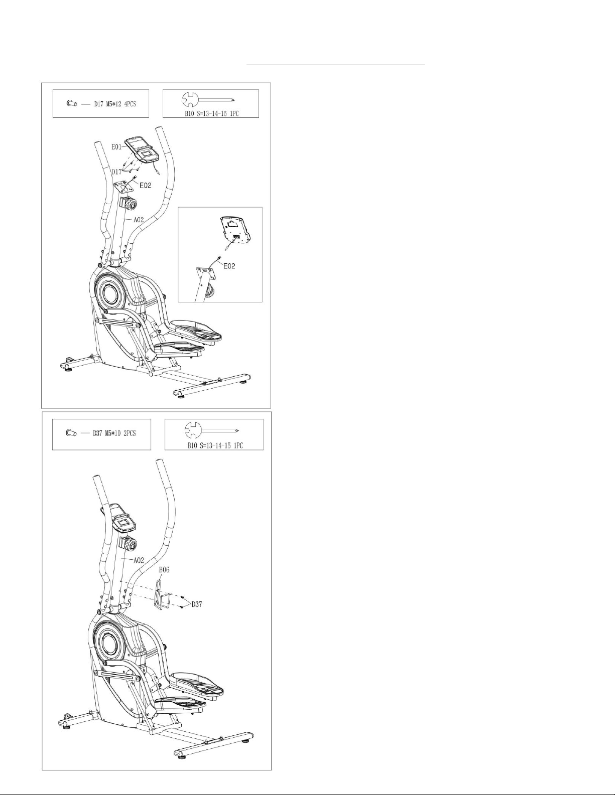
STEP 5:
Remove the 4 Bolts (No. D17) from the
back of the Computer (No. E01), set them
aside.
Connect the Sensor Wire (No. E02) with
the link wire of Computer (No. E01).
Attach the Computer (No. E01)
to the
bracket on the
Upright Post (No. A02)
using 4 Bolts (No. D17) that were removed.
Tighten and secure with Spanner (No.
B10).
STEP 6:
Attach the Bottle Holder (No. B06) to the
Upright Post (No. A02) using the 2 Bolts
(No. D37) that were removed. Tighten and
secure with Spanner (No. B10).
The assembly is complete!
9
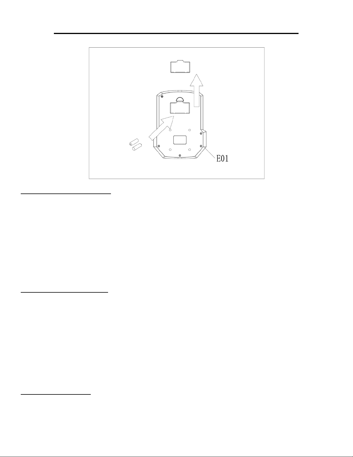
BATTERY INSTALLATION & REPLACEMENT
BATTERY INSTRALLATION
1. Take out 2 AAA batteries from computer box.
2. Press the buckle of battery cover on the Computer (No. E01), then remove battery cover.
3. Install 2 AAA batteries into the battery case on the back of the Computer (No. E01). Pay attention
to the battery + and - ends before installing.
4. Press the buckle of battery cover. Then, put the battery cover back on the Computer (No. E01).
The installation is complete!
BATTERY REPLACEMENT
1. Press the buckle of battery cover on the back of the Computer (No. E01). Then remove battery
cover.
2. Remove the 2 old AAA batteries in the battery case and install 2 new AAA batteries into the battery
case on the back of the Computer (No. E01). Pay attention to the battery + and - ends before
installing.
3. Press the buckle of battery cover. Then, put the battery cover back on the Computer (No. E01).
The replacement is complete!
BATTERY DISPOSAL
Dispose the batteries according to the laws and regulations of your local region. Some batteries may
be recycled. When disposing or recycling, do not mix battery types.

10
ADJUSTMENTS & USAGE GUIDE
ADJUSTING THE TENSION OF THE ELLIPTICAL
CLIMBER
Adjust the tension of the elliptical climber by rotating the
Tension Control Knob (No. C06) clockwise to increase
the level of resistance. Rotate the Tension Control
Knob (No. C06) counter-clockwise to decrease the level
of resistance.
Tension levels are set at Level 1 being the lowest and
Level 8 being the highest.
ADJUSTING THE BALANCE OF THE ELLIPTICAL
CLIMBER
If you find that the elliptical climber is unbalance
d and
causes
excessive movement when in use, you can
adjust the elliptical climber balance. Use the Spanner
(No. B10) to loosen the Nut (No. D34). Adjust the Foot
Pad (No. C22) on the Front & Rear Stabilizers (No.
A11 & No. A12) of each side if needed. After adjusting,
tighten and secure with the Spanner (No. B10).
MOVING THE ELLIPTICAL CLIMBER
To move the elliptical climber, hold the Left Handlebar
(No. A09) and Right Handlebar (No. A10) and tilt it
until the Transportation Wheel (No. C21)
touch the
ground. With the wheels on the ground, you can
transport it to the desired location with ease.
CLEANING
The elliptical climber
can be cleaned with a soft, clean, and damp cloth. Do not use abrasives
or solvents on plastic parts. Please wipe your perspiration off the elliptical climber
after each
use. Be careful not to get excessive moisture on the computer
display panel as this might
cause an electrical hazard or computer failure.
Please keep the elliptical climber
, especially the computer, out of direct sunlight to prevent
screen damage.
Please inspect all assembly bolts and pedals on the machine for proper tightness every week.
STORAGE
Store the elliptical climber in a clean and dry environment away from children.

11
EXERCISE COMPUTER
FUNCTION BUTTONS:
MODE:
1. Press the button to select TIME, DISTANCE and CAL to preset.
2. Press the button for selecting function display on main LCD or enter after
setting.
3. Press the button and hold for 3 seconds to reset all values except
Odometer to zero.
(When the user replaces batteries, all the values will reset to ZERO
automatically.)
SET:
1. To set up the target value of TIME, DISTANCE and CAL.
2. Press the button and hold for 2 seconds to speed up the increments.
RESET:
1. Press the button to reset function value when setting.
2. Press the button and hold for 3 seconds to reset all values except odometer to zero.
(When the user replaces batteries, all the values will reset to ZERO automatically)
FUNCTIONS & OPERATIONS:
1. BATTERY INSTALLATION:
Please install 2 AAA 1.5V batteries in the battery case on the back of computer. (Whenever batteries
are removed, all the function values will be reset to zero.)
2. AUTO ON/OFF:
Once the user begins to exercise, the computer
will show the workout value automatically. After about
4 minutes of inactivity, the computer will turn off. The Odometer value does not reset to 0 when the
computer turns off. When the user starts to exercise again, the workout value of the Odometer will
accumulate continuously.
3. AUTO SCAN:
After the computer is powered on, press the Mode button. The LCD will display all function values
from TIME-SPEED-DISTANCE-CALORIES-ODOMETER. Each value will be displayed for 6 seconds.
4. SPEED:
Displays the current training speed from 0.0 MPH to 99.9 MPH (Miles per hour).
5. DISTANCE:
Records total distance from 0.0 M up to 9999 M (Mile). The user may preset target time by pressing
the SET & MODE buttons. Each increment is 0.1 M (Mile). Automatically counts down from target
value during exercise.

12
6. TIME:
Records total time from 00:00 up to 99:59. The user may preset target time by pressing SET & MODE
buttons. Each increment is 1 minute.
Automatically counts down from target value during exercise.
7. CALORIES:
Records calories burn
ed during training from 0 KCAL to 9999 KCAL. The user may also preset the
target calorie before training by pressing the SET & MODE button. Each setting increase is 1 CAL.
Automatically counts down from target value during exercise.
Note: This data is a rough guide which cannot be used in medical treatment.
8. ODOMETER:
Displays the total distance from 0 M to 9999 M (Mile)
. User can also press mode key to display the
Odometer value.
9. RESET:
Press the button and hold for 2 seconds to reset all value except Odometer to zero.
NOTE:
1. If the computer display is abnormal, please re-
install the batteries and try again. Always change both
batteries at the same time. Do not mix battery types and do not mix old and new batteries.
2. Battery Spec: 1.5V UM-4 or AAA (2PCS).
3. Dispose the batteries safely and according to your state and regional guidelines.
TROUBLESHOOTING
PROBLEM
SOLUTION
There is no display on th
e
computer
1. Remove the computer and verify that the wire from the
computer is properly connected to the wire that comes from the
upright post.
2. Check if the batteries are correctly positioned an
d that the
battery springs are in proper contact with batteries.
3. The batteries in the computer may be unresponsive. Change to
new batteries.
The elliptical climber
wobbles when in use
Turn the adjustable end caps on the rear stabilizer as needed to
level the elliptical climber.
The elliptical climber
makes a
squeaking noise
when in use.
The bolts may have become loosened on the elliptical climber.
Please inspect all the bolts and tighten any
that may have
loosened.
NOTE: If you are unable to resolve an issue using the troubleshooting guide above, please contact
Customer Service at support@sunnyhealthfitness.com
Version: 1.2