
SMART FOLDABLE STAIR CLIMBER
WITH RESISTANCE BANDS
SF-S025005
USER MANUAL
IMPORTANT! Please retain owner’s manual for maintenance and adjustment instructions. Your
satisfaction is very important to us, PLEASE DO NOT RETURN UNTIL YOU HAVE CONTACTED
US: support@sunnyhealthfitness.com or 1- 877 - 90SUNNY (877-907-8669).

1
IMPORTANT SAFETY INFORMATION
We thank you for choosing our product. To ensure your safety and health, please use this equipment
correctly. It is important to read this entire manual before assembling and using the equipment. Safe
and effective use can only be achieved if the equipment is assembled, maintained, and used
properly. It is your responsibility to ensure that all users of the equipment are informed of all warnings
and precautions.
1. Before starting any exercise program, you should consult your physician to determine if you have
any medical or physical condition that could put your health and safety at risk or prevent you from
using the equipment properly. Your physician’s advice is essential if you are taking medication that
affects your heart rate, blood pressure or cholesterol level.
2. Be aware of your body’s signals. Incorrect or excessive exercise can damage your health. Stop
exercising if you experience any of the following symptoms: pain, tightness in your chest, irregular
heartbeat, shortness of breath, lightheadedness, dizziness, or feelings of nausea. If you do
experience any of these conditions, you should consult your physician before continuing with your
exercise program.
3. Keep children and pets away from the equipment. The equipment is designed for adult use only.
4. Use the equipment on a solid, flat level surface with a protective cover for your floor or carpet. To
ensure safety, the equipment should have at least 2 feet (60 cm) of free space all around it.
5. Ensure that all nuts and bolts are securely tightened before using the equipment. The safety of the
equipment can only be maintained if it is regularly examined for damage and/or wear and tear.
6. Always use the equipment as indicated. If you find any defective components while assembling or
checking the equipment, or if you hear any unusual noises coming from the equipment during
exercise, discontinue use of the equipment immediately and do not use until the problem has been
rectified.
7. Wear suitable clothing while using the equipment. Avoid wearing loose clothing that may become
entangled in the equipment.
8. Do not place fingers or objects into the moving parts of the equipment.
9. The maximum weight capacity of this unit is 330 lbs (150kg).
10. The equipment is not suitable for therapeutic use.
11. To avoid bodily injury and/or damage to the product or property, proper lifting and moving are
required.
12. Your product is intended for use in cool and dry conditions. You should avoid storage in extremely
cold, hot or damp areas as this may lead to corrosion and other related problems.
13. This equipment is designed for indoor and home use only; it is not intended for commercial use.
2
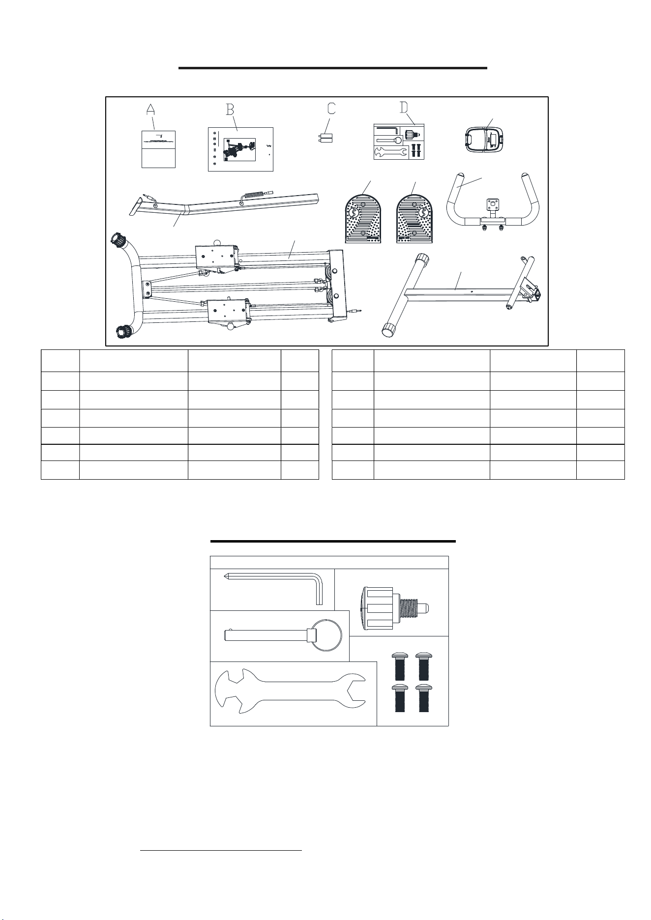
PRE-ASSEMBLY CHECK LIST
Before you start to assemble, please make sure all parts are included.
No.
Description Spec. Qty.
No. Description Spec. Qty.
1 Front Support Tube
1 31 Right Pedal 120 1
2 Main Frame 1 A Thank You Card 1
3 Handlebar Post 1 B Manual 1
4 Handlebar 1 C Battery AAA 1.5V 2
22 Computer DSC03676 1 D Hardware Package 1
25 Left Pedal 120 1
HARDWARE PACKAGE
Ordering Replacement Parts
Please provide the following information in order for us to accurately identify the part(s) needed:
The model number
The product name
The part number
Please contact us at support@sunnyhealthfitness.com or 1- 877 - 90SUNNY (877-907-8669)
3
UNNY
W W W.S U N N Y H E A L T H F I T N E S S.C O M
IMPORTANT! Pleas e re tain owne r’s manual for m aintena nce and adjustme nt instructions. Your
satisf action is ver y important to us, PLE ASE DO NOT RETURN UNTIL Y OU HAVE CONTACTED
US: supp ort@su nnyhea lthfitness.com or 1-877-9 0SUNNY (877-907-8669).
SMAR T FOLDABLE STAIR C LIMBER
WITH RESISTAN CE BANDS
SF-S025005
H E A L T H & F I T N E S S
THANK
YOU
FOR YOUR PURCHASE
UNNY
22
2
1
4
31
25
USER MANUAL
#24 M8*20 4PCS
#15 Φ38*L65*M16 *1.5 1PC
#16 Φ10*70 1PC
#43 S13-S15-S17 1PC
#44 S5 1PC
SF-S025005 HARDWARE PACKAGE
STEP 2
STEP 4
STEP 1
#24 M8*20 4PCS
#15 Φ38*L65*M16*1.5 1PC
#16 Φ10*70 1PC
#43 S13-S15-S17 1PC
#44 S5 1PC
SF-S025005 HARDWARE PACKAGE
STEP 2
STEP 4
STEP 1
3
ASSEMBLY INSTRUCTIONS
We value your experience using Sunny Health and Fitness products. For assistance with parts or
troubleshooting, please contact us at support@sunnyhealthfitness.com or 1-877-90SUNNY (877-
907-8669).
16
17
17
1
2
#17 Φ10*M8*20 2PCS
#44 S5 1PC
#16 Φ10*70 1PC
16
2
1
1
29
13
15
3
29
13
#15 Φ38*L65*M16*1.5 1PC
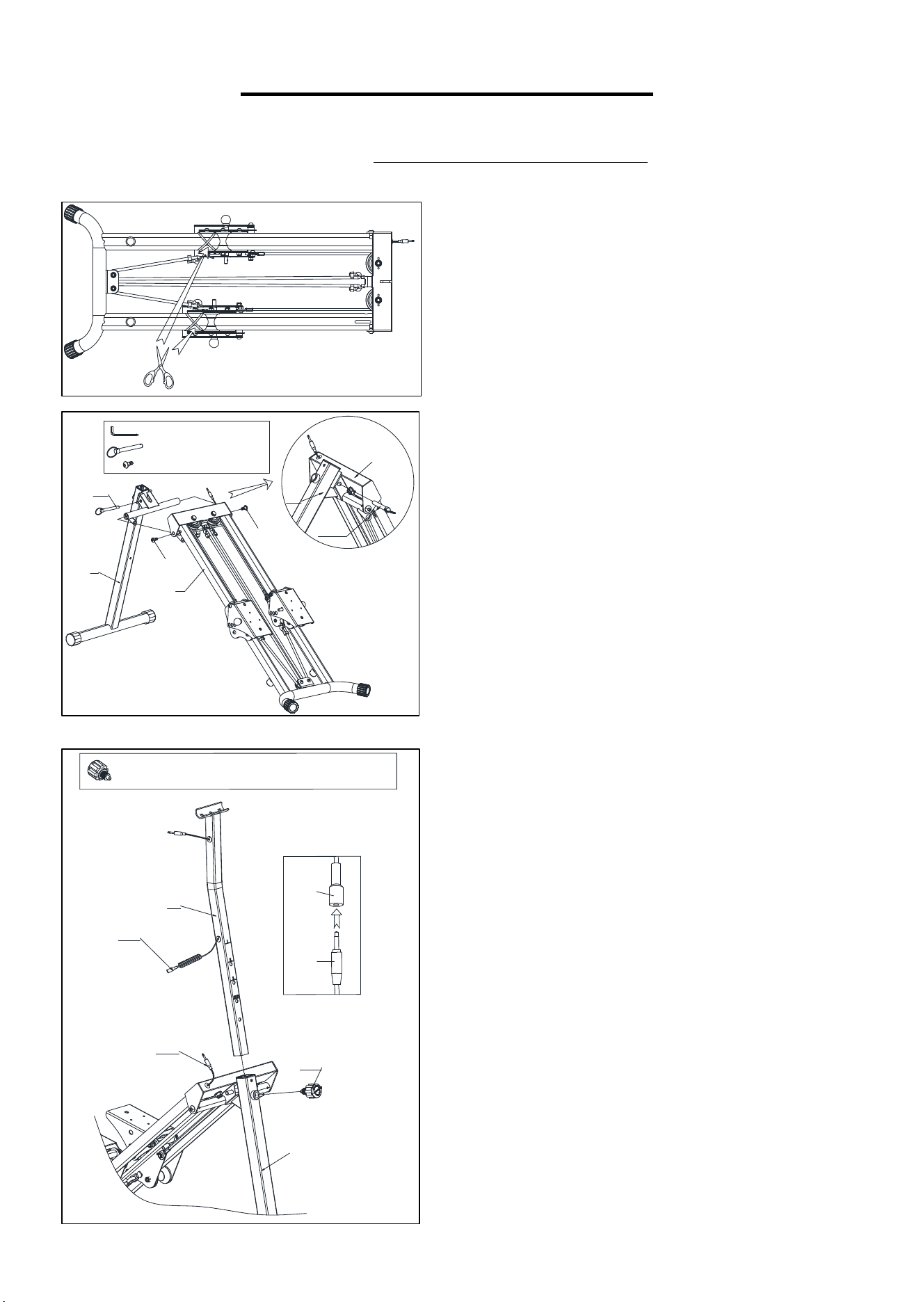
STEP 1:
Please cut the nylon ties before assembly.
Remove 2 Bolts (No. 17) from the Front Support
Tube (No. 1) with Allen Wrench (No. 44).
Attach Front Support Tube (No. 1) to Main Frame
(No. 2) using 2 Bolts (No. 17)
that were
removed. Tighten and
secure with Allen Wrench
(No. 44).
Insert and secure the Pull Ring Pin (No. 16) into
the Front Support Tube (No. 1) & Main Frame (No.
2).
ATTENTION: When setting up the machine, the Pull
Ring Pin (No. 16) must be inserted through the
fixed holes of Front Support Tube (No. 1) and Main
Frame (No. 2). After the pin is installed, please
double check to confirm that the pin is securely in
place. Improper installation may result in a risk of
injury from falls.
STEP 2:
Insert the Handlebar Post (No. 3) into the Front
Support Tube (No. 1), adjust the Handlebar Post
(No. 3) to desired height, then secure it in place by
inserting and tightening the Knob (No. 15).
Connect the Middle Sensor Wire (No. 13) with the
Sensor Wire (No. 29).
4
We value your experience using Sunny Health and Fitness products. For assistance with parts or
troubleshooting, please contact us at support@sunnyhealthfitness.com or 1-877-90SUNNY (877-907-
8669).
3
10
11
11
10
8
8
4
#43 S13-15-17 1PC
#8 M8*40.5 2PCS
#10 OD16*ID8*δ1.5 2PCS
#11 M8 2PCS
25
24
7
23
7
23
31
2424
2
#44 S5 1PC
#23 Φ10*115 2PCS
#24 M8*20 4PCS
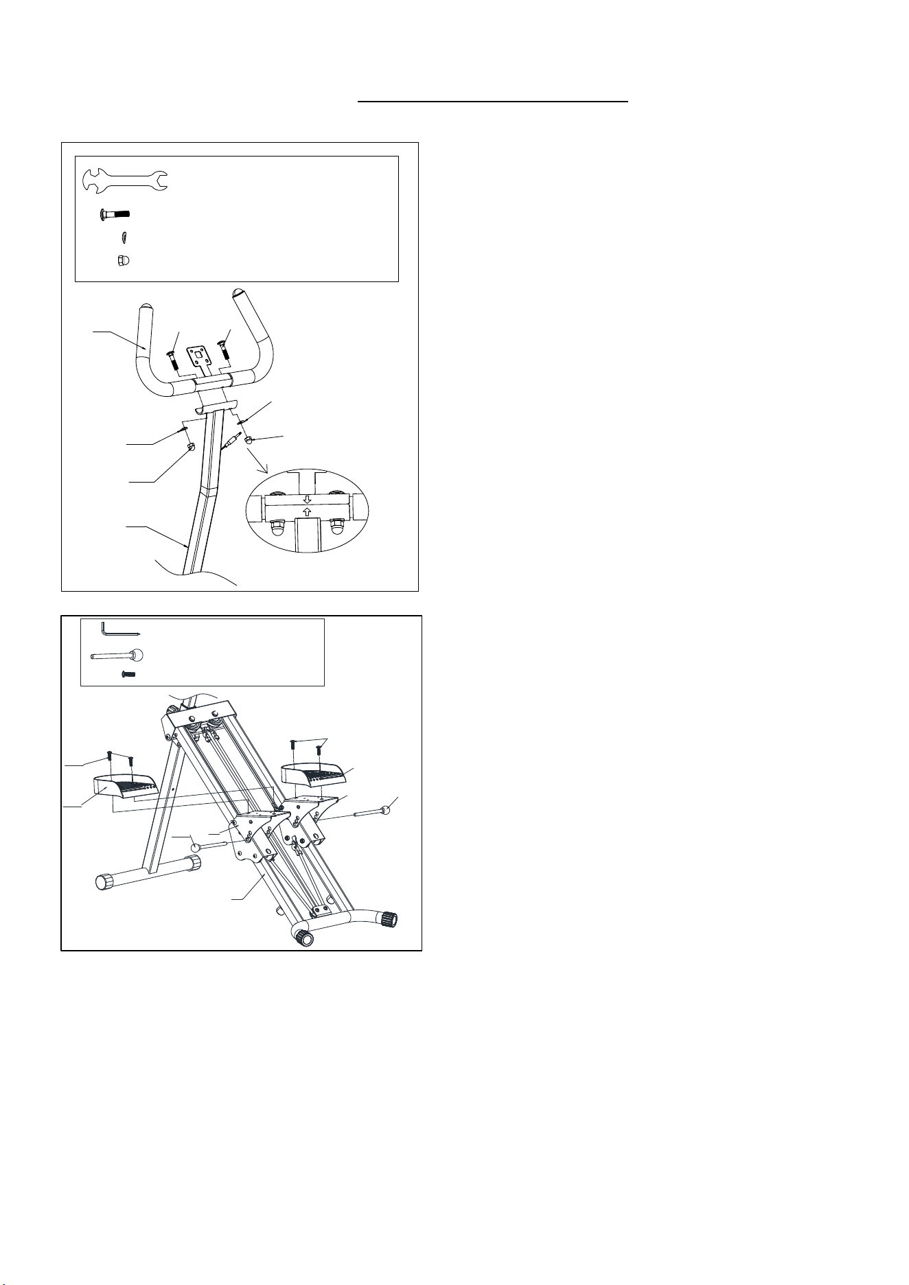
STEP 3:
Remove 2 Bolts (No. 8), 2 Curved Gaskets (No.
10) and 2 Cap Nuts (No. 11) from the Handlebar
(No. 4) with Spanner (No. 43).
Attach Handlebar (No. 4) to Handlebar Post (No.
3) using 2 Bolts (No. 8), 2 Curved Gaskets (No.
10) and 2 Cap Nuts (No. 11)
that were
removed. Tighten and
secure with Spanner
(No. 43).
NOTE: To properly install Handlebar (No. 4),
make sure the arrows are on the same side and
pointing to each other.
STEP 4:
Remove 2 Ball Head Pins (No. 23) from the 2
Pedal Adjustment Plates (No. 7).
Attach the Left Pedal (No. 25) onto the Pedal
Adjustment Plate (No. 7) on the left side with 2
Hexagon Bolts (No. 24). Tighten and secure with
the Allen Wrench (No. 44). Adjust the Pedal
Adjustment Plate (No. 7) to desired height, then
secure it in place by inserting the Ball Head Pin
(No. 23) that were removed.
Please repeat this assembly step to the right side.
NOTE: Make sure to keep the Left & Right
pedals (No. 25 & No. 31) at the same angle to
ensure safer use.
5
We value your experience using Sunny Health and Fitness products. For assistance with parts or
troubleshooting, please contact us at support@sunnyhealthfitness.com or 1-877-90SUNNY (877-907-
8669).
4
41
22
13
#44 S5 1PC
#41 M5*10 4PCS
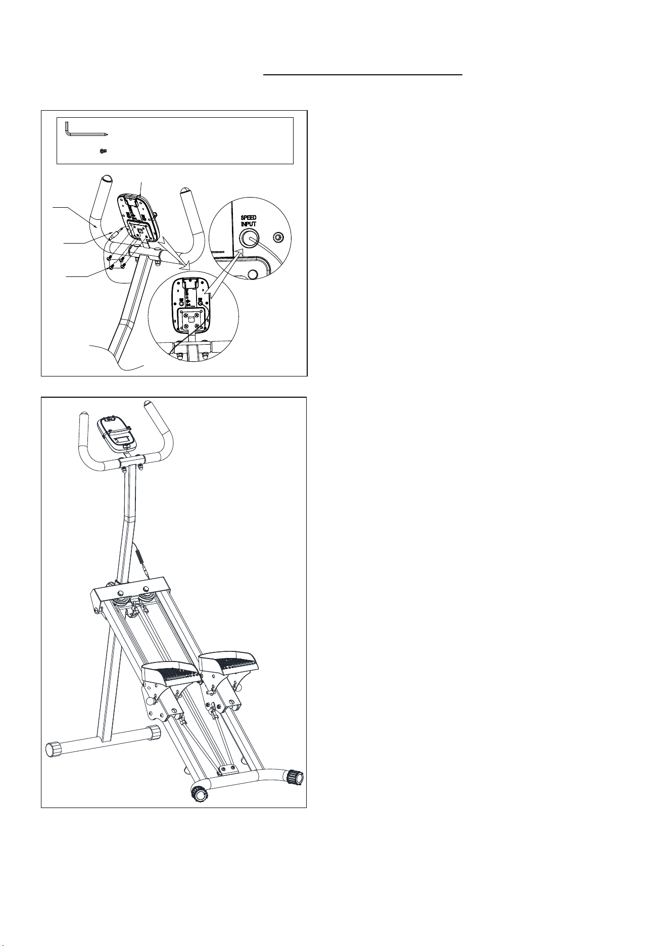
STEP 5:
Remove 4 Screws (No. 41) from the back of the
Computer (No. 22) by using Allen Wrench (No.
44).
Attach the Computer (No. 22) onto the bracket of
the Handlebar (No. 4) with 4 Screws (No. 41)
that were removed. Tighten and
secure with
Allen Wrench (No. 44).
Insert the Middle Sensor Wire (No. 13) into the
SPEED INPUT of the Computer (No. 22).
The assembly is complete
!
6
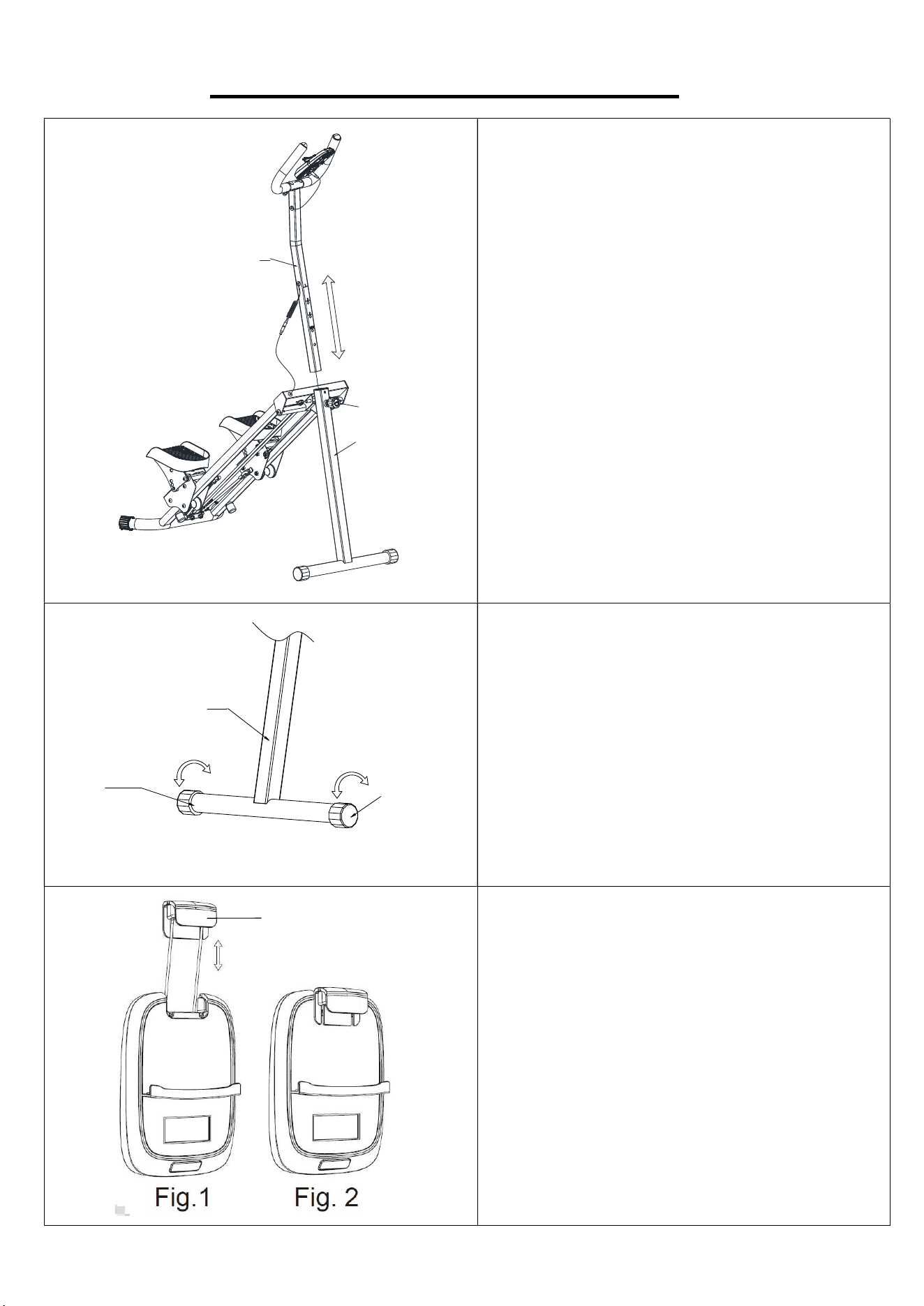
ADJUSTMENT & USAGE GUIDE
ADJUSTING THE HANDLEBAR
Loosen the Knob (No. 15) and pull out. Raise
or lower the Handlebar Post (No. 3) to desired
height. Then reinsert and tighten the Knob (No.
15).
ADJUSTING THE BALANCE
In order to achieve a smooth and comfortable
ride, you must ensure that the stair climber is
stabled and secured. If you notice that the stair
climber is unbalanced during use, you should
adjust the 2 End Caps (No. 18) located on the
Front Support Tube (No. 1) until the stair
climber becomes levelled with the floor surface.
The SUNNY insert (No. A) can be pulled
upward to secure the mobile device in place (as
shown in Fig. 1). When the mobile device is
placed horizontally, please move the SUNNY
insert (No. A) in front of the computer after it is
pulled out (as shown in Fig. 2) to avoid the
insert from returning back into the meter.
15
1
3
1
18
18
A
7
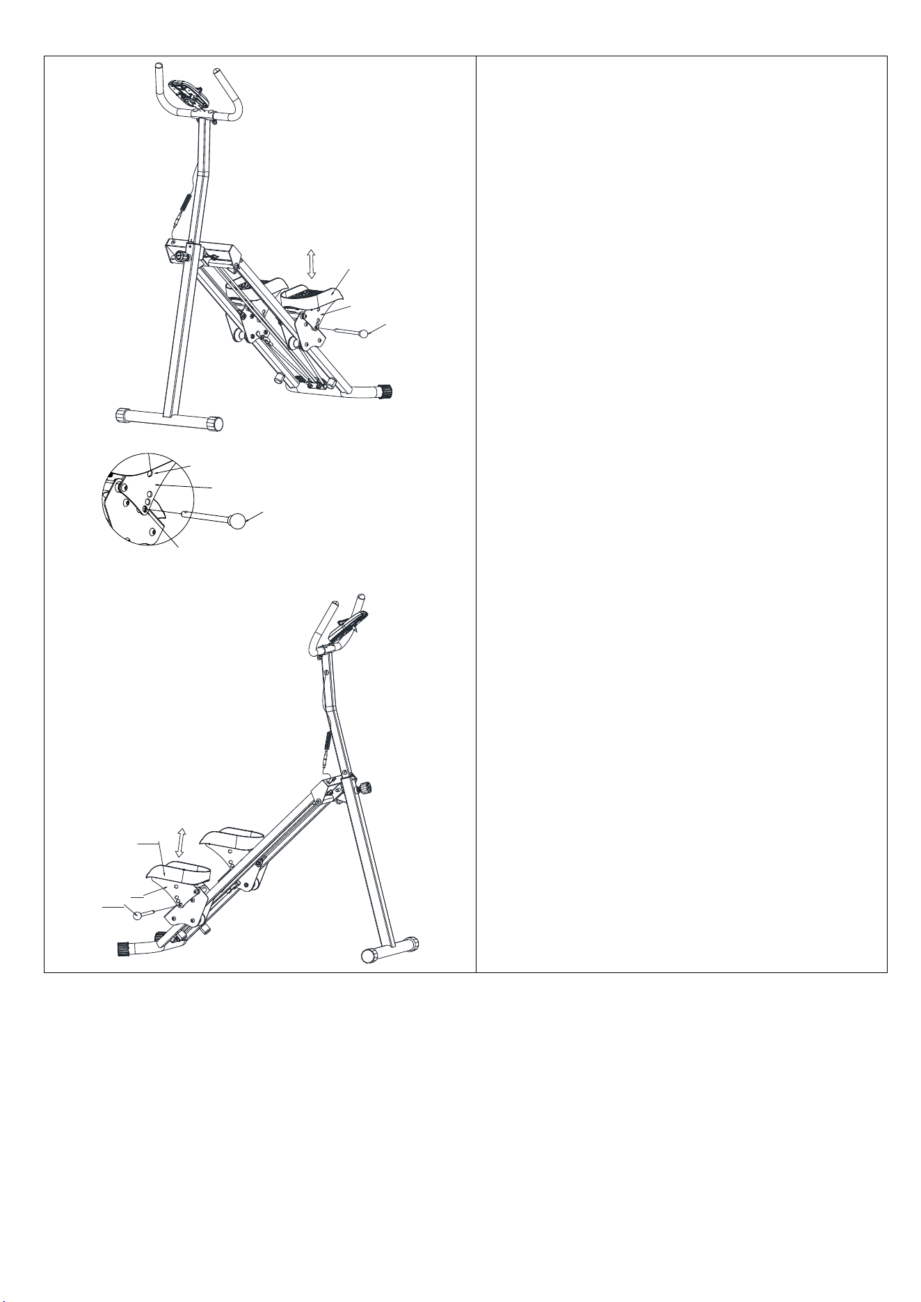
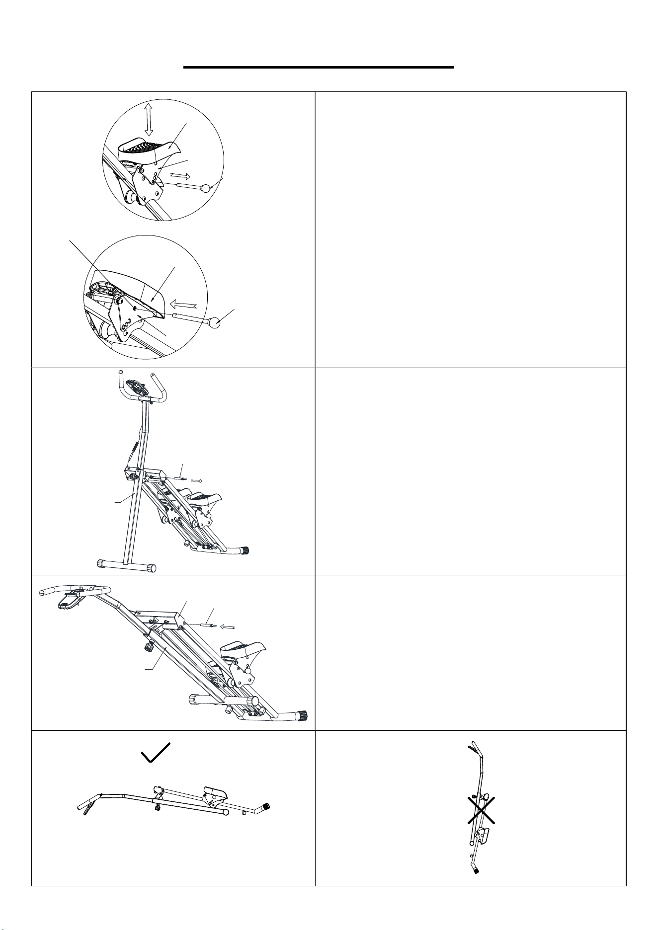
ADJUSTING THE PEDAL
To adjust the Left & Right Pedal (No. 25 & No.
31), remove the 2 Ball Head Pins (No. 23)
and rotate the Left & Right Pedal (No. 25 &
No. 31) to desired position. Re-insert the 2
Ball Head Pins (No. 23) to secure.
NOTE:
Keep the two pedals at the same angle to
ensure safer use.
23
7
25
23
These three are the
pedal angle adjustment holes
Storage hole
7
23
31
7
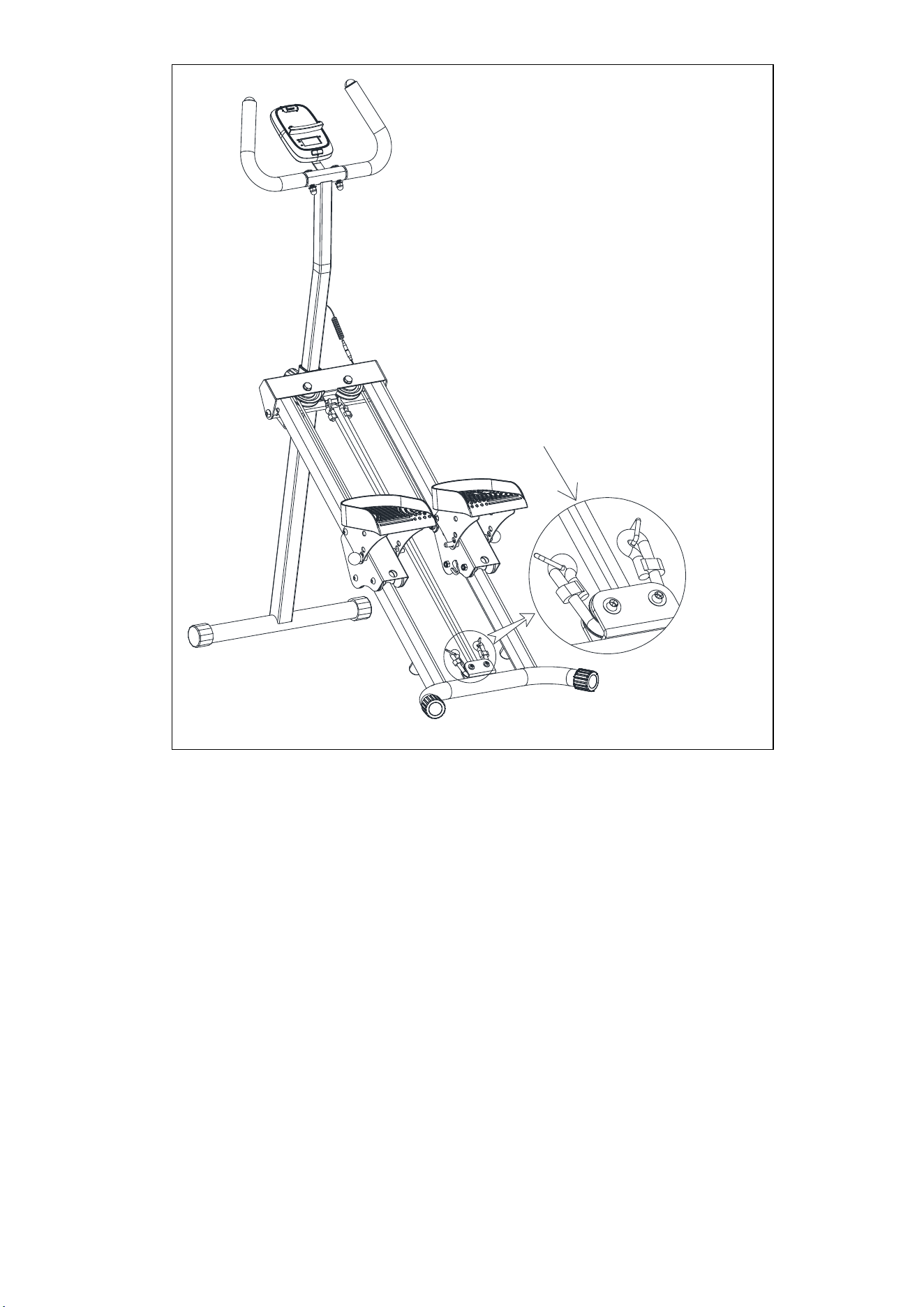
8
Note:
To perform the exercise without resistance, simply detach the Resistance Bands (No. 47). (See the
figure above.)
When the Resistance
Bands (No. 47) are
placed here, the
equipment can be used
without resistance.
9
FOLDING INSTRUCTIONS
A. Remove the Ball Head Pins (No. 23) from the
Pedal Adjustment Plates (No. 7).
Bring the Pedal Adjustment Plate (No. 7) and
the Left Pedal (No. 25) closer to each other.
Insert the Ball Head Pins (No. 23) into the
storage hole on the Pedal Adjustment Plate
(No. 7).
Then repeat the same step for right side.
B. Remove the Pull Ring Pin (No. 16) from the
Front Support Post (No. 1).
C. Bring the Front Support Tube (No. 1) and the
Main Frame (No. 2) closer to each other. I
nsert
the Pull Ring Pin (No. 16) into the hole on the
Main Frame (No. 2).
23
7
25
23
7
25
16
1
16
2
1
Storage hole
10
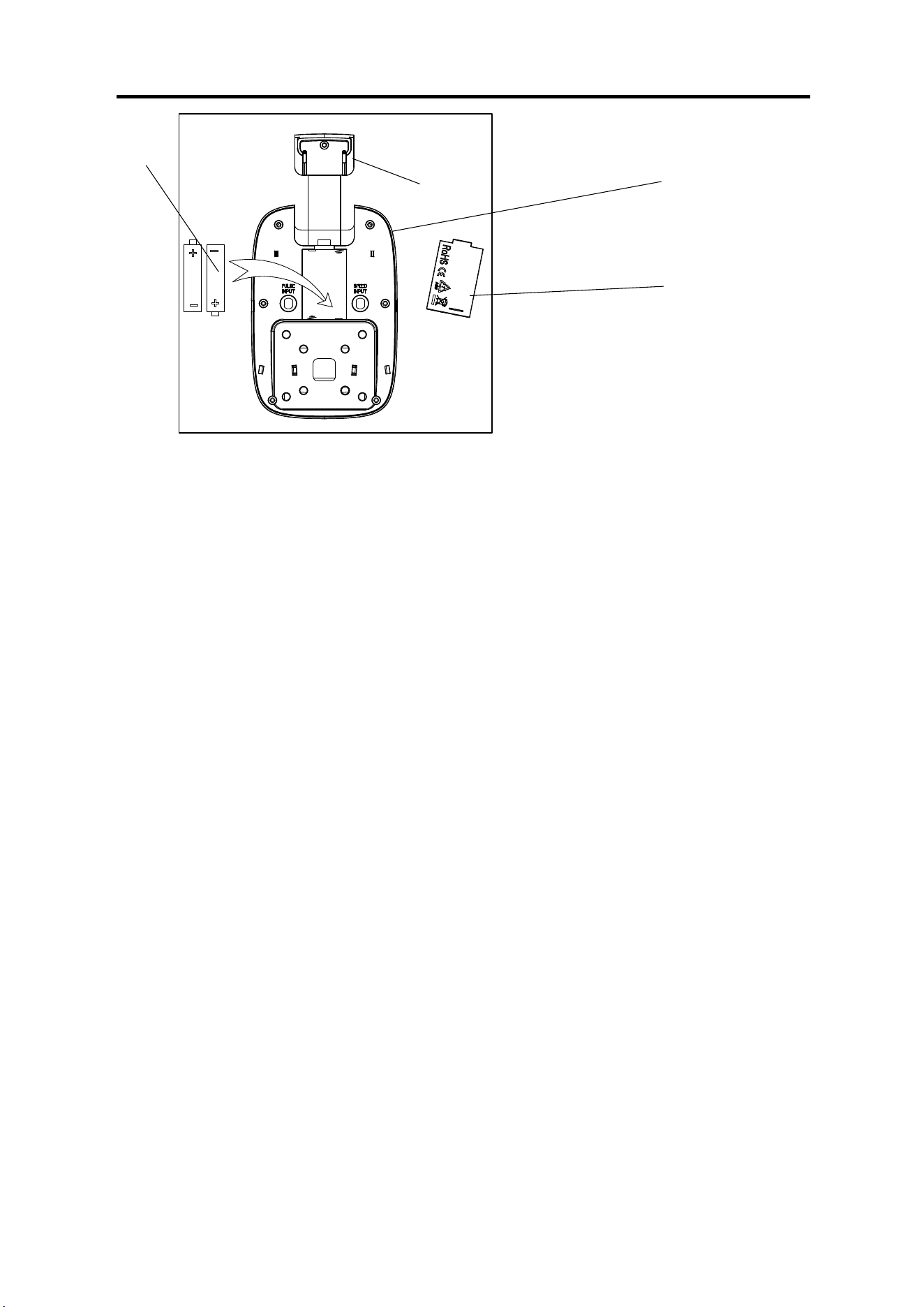
BATTERY INSTALLATION AND REPLACEMENT
BATTERY INSTALLATION:
1. Take out 2 AAA batteries from computer box.
2. Pull out the SUNNY insert (No. A), press the buckle of battery cover on the Computer (No. 22), then
remove battery cover.
3. Install 2 AAA batteries into the battery case on the back of the Computer (No. 22). Pay attention to
the battery + and – poles before installing.
4. Press the buckle of battery cover, then put the battery cover back to the back of the Computer (No.
22).
The installation is complete!
BATTERY REPLACEMENT:
1. Press the buckle of battery cover on the back of the Computer (No. 22), then remove battery cover.
2. Remove the 2 old AAA batteries in the battery case and install 2 new AAA batteries into the battery
case on the back of the Computer (No. 22). Pay attention to the battery + and – poles before installing.
3. Press the buckle of the battery cover, then put the battery cover back to the back of the Computer
(No. 22).
The replacement is complete!
NOTE: Always change both batteries at the same time. Do not mix battery types and do not mix old
and new batteries. Dispose batteries according to your state and regional guidelines.
Battery Cover
Battery
22
A
11
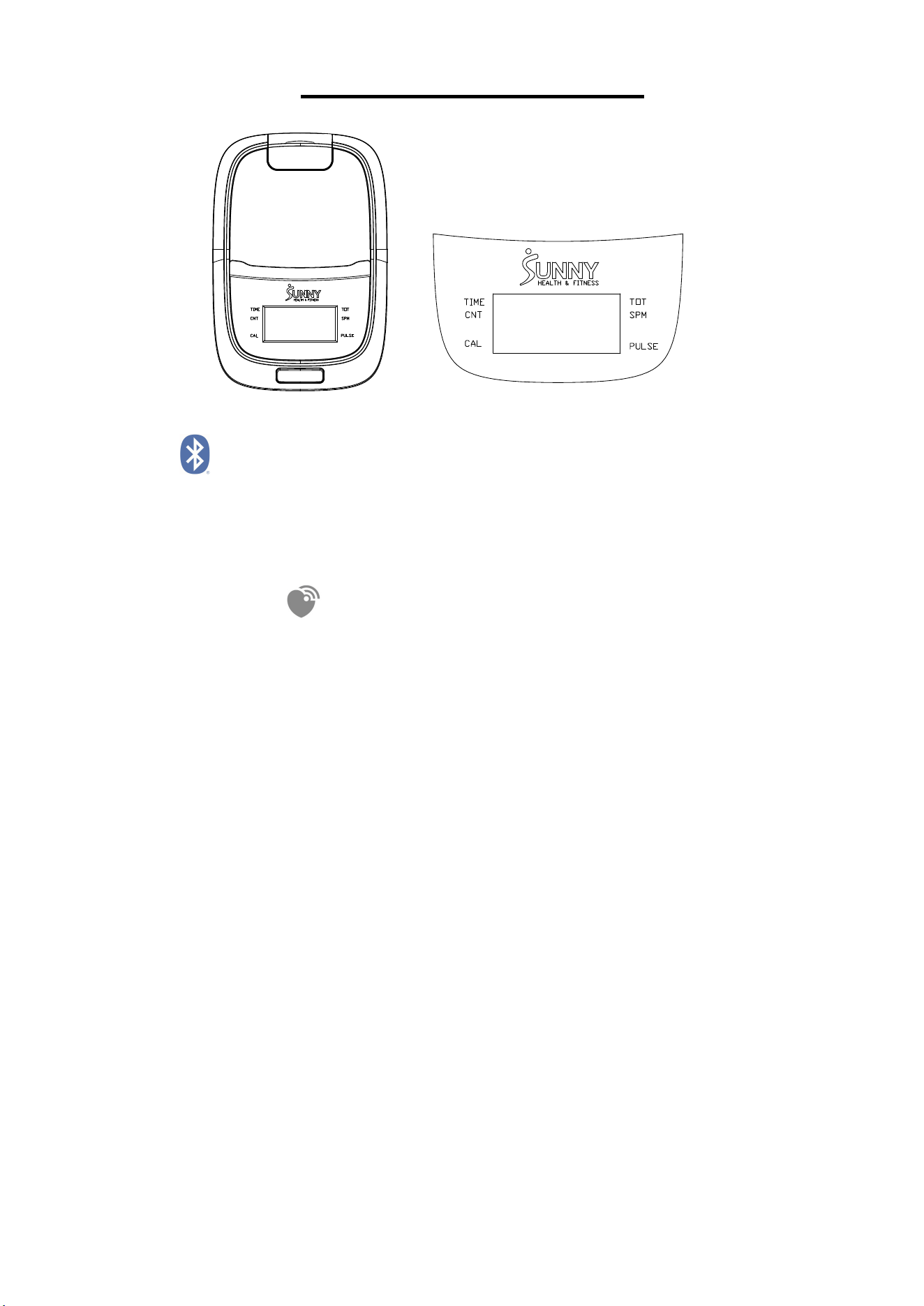
EXERCISE COMPUTER
BLUETOOTH :
1. The Bluetooth icon will flash when the computer is on or wakes from sleep mode. If no Bluetooth
connection is established within 3 minutes, the Bluetooth icon will turn off.
2. The Bluetooth icon will stay on when it is connected.
WIRELESS HEART RATE
1. The wireless heart rate icon will flash when the computer is on. If the heart rate monitor is not
connected within 1 minute, the wireless heart rate icon will turn off.
2. After exercise resumes, the wireless heart rate icon will flash. If the heart rate monitor is not
connected within 1 minute, the wireless heart rate icon will turn off.
3. When the computer wakes from sleep mode, the wireless heart rate icon will flash. If the heart rate
monitor is not connected within 1 minute, the wireless heart rate icon will turn off.
4. The wireless heart rate icon will flash when the MODE key is pressed. If the heart rate monitor is
not connected within 1 minute, the wireless heart rate icon will turn off.
5. The wireless heart rate icon will stay on when the heart rate monitor is connected.
NOTE: The heart rate monitor is not included. Wireless heart rate function works with SunnyFit Heart
Rate Monitor HR200. HR200 can only connect to the computer when the wireless heart rate icon is
flashing.
FUNCTION BUTTON
MODE
Press the button to switch display or automatically display through each function value in sequence
every 6 seconds.
Hold the MODE key for 2 seconds to reset all values except TOT when Bluetooth is not connected.
Press and hold the MODE key for 6 seconds to disconnect from both the SunnyFit APP and the heart
rate monitor; then, the computer will enter sleep mode.

12
OPERATION
1.POWER ON
Installs 2 pieces of 1.5V AAA batteries. (Whenever batteries are removed, all the functions values will
be reset to zero.)
2.1 WAKE UP
After entering speed signal, each function will skip to display. STOP will be displayed once no speed
signal detected for 10 seconds.
2.2 SLEEP MODE
The computer will shut off automatically and disconnect the heart rate monitor if there is no activity for
4 minutes when Bluetooth is not connected.
3.SCAN
After power on or press the MODE button, automatically scan through each function value in
sequence every 6 seconds. SCAN-->TIME-->CNT (COUNT)-- >CAL (CALORIES)-->TOT (TOTAL
COUNTS)-->SPM-->PULSE-->SCAN
4.TIME
Accumulates total training time from 00:00 up to 999:59.
5.CNT (COUNT)
Display current training count from 0 up to 99999.
6.CAL (CALORIES)
Accumulates calories consumption during training from 0.0 up to 9999.9 kcal
NOTE: This data is a rough guide for comparison of different exercise sessions which can not be
used in medical treatment.
7.TOT (TOTAL COUNTS)
Accumulates training count from 0 up to 99999K.
8.SPM
Displays current step per minute.
9.PULSE (Needs to pair with the Bluetooth device)
Display the user's heart rate from 30-240 upon pulse signal detected with pulse symbol flashing. The
pulse graphic will not flashing upon no pulse signal detected.
NOTE:
1.If the computer displays abnormally, please re-install the battery and try again.
2.The batteries must be removed from the appliance before it is scrapped and that they are disposed
of safely.
3. The information displayed is an estimate only. Actual values may vary depending on factors such
as body weight, resistance level, workout intensity, and other individual conditions. This information is
provided for reference purposes only and should not be used for medical or dietary purposes.

13
TECHNICAL DATA
Connectivity: Bluetooth LE
Frequency Range: 2400~2483.5Mhz
Transmitting Power: 0dBm
APP CONNECTION:
Connect Smart Equipment to SunnyFit App:
1. Scan to download SunnyFit from the app store:
2. Ensure that the Bluetooth function is turned on from your mobile device.
3. If this is your first time using the SunnyFit app, follow the in-app instructions to register for your
free SunnyFit account and log in.
4. Begin any workout activity that matches your smart equipment, then follow the onscreen prompts
to search for and connect to your smart equipment.
5. When connected, your stats and records will be displayed at the end of your course/session, and
recorded in your account profile!
Troubleshooting:
If you are having trouble connecting your smart equipment, visit www.sunnyfit.com/guide or scan
the QR code below:
If you require additional support, please contact [email protected]
14
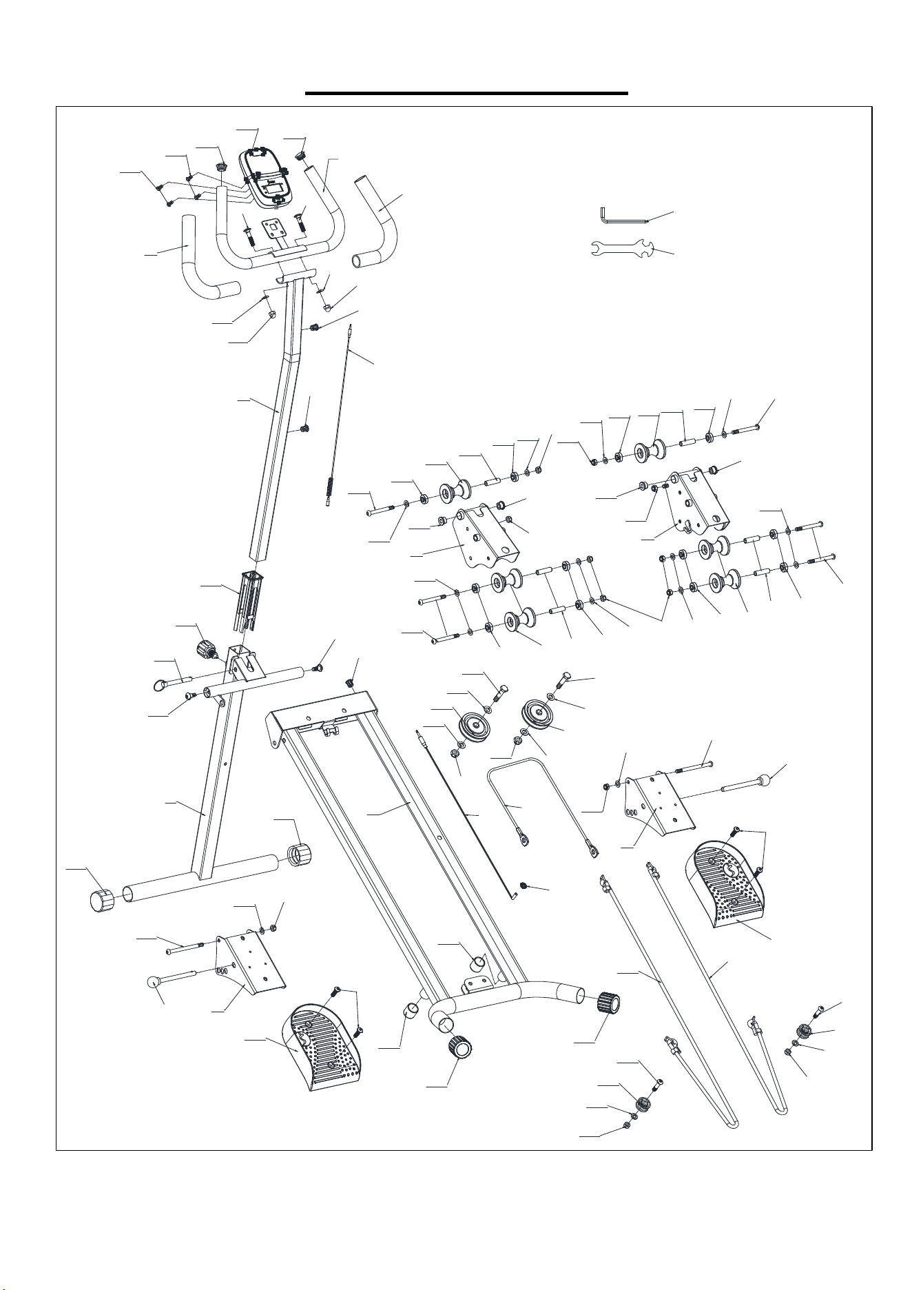
EXPLODED DIAGRAM
1
2
3
4
5
6
7
7
42
22
42
41
9
10
11
12
11
10
8
41
8
9
12
13
14
15
16
17
17
12
18
18
19
20
21
23
24
26
27
27
26
28
30
32
36
32
37
40
39
21
36
37
38
40
20
37
36
38
40
37
20
21
24
29
19
20
21
23
31
2424
33
34
33
34
33
33
35
35
38
37
20
21
37
36
37
20
21
39
21
37
38
40
39
39
20
20
20
20
43
44
21
25
46
20
21
46
20
21
47
47
45
45

15
PARTS LIST
No.
Description Spec. Qty.
No.
Description Spec. Qty.
1 Front Support Tube 1 25 Left Pedal 120 1
2 Main Frame 1 26 Cushion Φ30*Φ25*27 2
3 Handlebar Post 1 27 End Cap Φ38*1.5 2
4 Handlebar 1 28 Round Clasp Φ16.5*6.7 1
5 Left Pedal Support 1 29 Sensor Wire L=600 1
6 Right Pedal Support 1 30 Wire Rope Φ5*940 1
7 Pedal Adjustment Plate
2 31 Right Pedal 120 1
8 Bolt M8*40.5 2 32 Hexagon Bolt M10*45 2
9 Foam Grip Φ30*Φ24*285 2 33 Flat Washer d10*Φ20*1.5 4
10 Curved Gasket OD16*ID8*δ1.5
2 34 Pulley Φ75*22 2
11 Cap Nut M8 2 35 Lock Nut M10 2
12 Grommet Φ12 3 36 Hexagon Bolt M8*80 6
13 Middle Sensor Wire L500 1 37 Bearing 608ZZ 12
14 Bushing
38*1.5,L153
1 38 Roller Φ47*Φ12*59 6
15 Knob
Φ38*L65*M16*
1.5
1 39 Spacer Φ20*Φ8.5*11 4
16 Pull Ring Pin Φ10*70 1 40 Spacer Φ11*Φ8.1*40.1 6
17 Bolt Φ10*M8*20 2 41 Screw M5*10 4
18 End Cap Φ38*1.5 2 42 End Cap Φ25*1.5 2
19 Hexagon Bolt M8*105 2 43 Spanner S13-15-17 1
20 Flat Washer d8*Φ16*1.5 16 44 Allen Wrench S5 1
21 Lock Nut M8 12 45 Hexagon Bolt M8*35 2
22 Computer DSC03676 1 46 Pulley Φ32*Φ8.2*17 2
23 Ball Head Pin Φ10*115 2 47 Resistance Band Φ10*750 2
24 Hexagon Bolt M8*20 4
Version: 1.2

16