PREMIUM STEPPER STAIR CLIMBER
SF-X7300 SMART
USER MANUAL
IMPORTANT! Please retain owner’s manual for maintenance and adjustment instructions. Your
satisfaction is very important to us, PLEASE DO NOT RETURN UNTIL YOU HAVE
CONTACTED US: [email protected] or 1-877-90SUNNY (877-907-8669).

1
IMPORTANT SAFETY INSTRUCTIONS
We thank you for choosing our product. To ensure your safety and health, please use this equipment
correctly. It is important to read this entire manual before assembling and using the equipment. Safe
and effective use can only be achieved if the equipment is assembled, maintained, and used properly.
It is your responsibility to ensure that all users of the equipment are informed of all warnings and
precautions.
1. Before starting any exercise program, you should consult your physician to determine if you have
any medical or physical condition that could put your health and safety at risk or prevent you from
using the equipment properly. Your physician’s advice is essential if you are taking medication that
affects your heart rate, blood pressure or cholesterol level.
2. Be aware of your body’s signals. Incorrect or excessive exercise can damage your health. Stop
exercising if you experience any of the following symptoms: pain, tightness in your chest, irregular
heartbeat, shortness of breath, lightheadedness, dizziness, or feelings of nausea. If you do
experience any of these conditions, you should consult your physician before continuing with your
exercise program.
3. Keep children and pets away from the equipment. The equipment is designed for adult use only.
4. Use the equipment on a solid, flat level surface with a protective cover for your floor or carpet. To
ensure safety, the equipment should have at least 8 feet (240 cm) of free space behind it and 2
feet (60 cm) on each side. Do not place the equipment on any surface that blocks air openings. To
protect the floor or carpet from damage, place a mat under the equipment.
5. Ensure that all nuts and bolts are securely tightened before using the equipment. The safety of the
equipment can only be maintained if it is regularly examined for damage and/or wear and tear.
6. Always use the equipment as indicated. If you find any defective components while assembling or
checking the equipment, or if you hear any unusual noises coming from the equipment during
exercise, discontinue use of the equipment immediately and do not use until the problem has
been rectified.
7. Wear suitable clothing while using the equipment. Avoid wearing loose clothing that may become
entangled in the equipment.
8. Do not place fingers or objects into the moving parts of the equipment.
9. The maximum weight capacity of this unit is 400 lbs (180 kgs).
10. The equipment is not suitable for therapeutic use.
11. To avoid bodily injury and/or damage to the product or property, proper lifting and moving are
required.
12. Your product is intended for use in cool, dry conditions. You should avoid storage in extremely
cold, hot, or damp areas as this may lead to corrosion and other related problems.
13. This equipment is designed for indoor and home use only, it is not intended for commercial use!

2
IMPORTANT SAFETY INSTRUCTIONS
When using an electrical appliance, basic precautions should always be followed, including the
following:
Read all instructions before using (this appliance).
DANGER – To reduce the risk of electric shock and the injury from moving parts:
Always unplug this appliance from the electrical outlet immediately after using and before cleaning or
servicing.
WARNING – To reduce the risk of burns, fire, electric shock, or injury to persons:
1) An appliance should never be left unattended when plugged in. Unplug from outlet when not in
use, and before putting on or taking off parts.
2) This appliance is not intended for use by persons with reduced physical, sensory, or mental
capabilities, or lack of experience and knowledge, unless they have been given supervision or
instruction concerning use of the appliance by a person responsible for their safety. Keep children
under the age of 13 away from this machine.
3) Use this appliance only for its intended use as described in this manual. Do not use attachments
not recommended by the manufacturer.
4) Never operate this appliance if it has a damaged cord or plug, if it is not working properly, if it has
been dropped or damaged, or dropped into water. Return the appliance to a service center for
examination and repair.
5) Do not carry this appliance by supply cord or use cord as a handle.
6) Keep the cord away from heated surfaces.
7) Never operate the appliance with the air openings blocked. Keep the air openings free of lint, hair,
and the like.
8) Never drop or insert any object into any opening.
9) Do not use outdoors. Household use only.
10) Do not operate where aerosol (spray) products are being used or where oxygen is being
administered.
11) To disconnect, turn all controls to the off position, then remove plug from outlet.
12) CAUTION: Risk of Injury to Persons – To Avoid Injury, use extreme caution when stepping onto or
off of a moving belt. Read Instruction Manual Before Using.
13) Connect this appliance to a properly grounded outlet only. See Grounding Instructions.
SAVE THESE INSTRUCTIONS
3
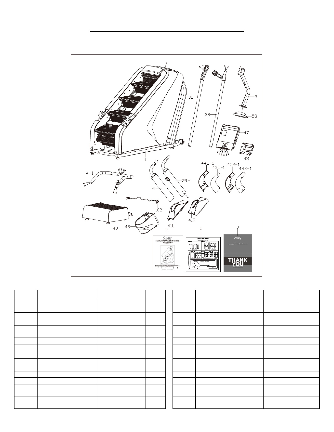
PRE-ASSEMBLY CHECK LIST
Before you start to assemble, please make sure all parts are included.
No.
Description
Spec.
Qty.
No.
Description
Spec.
Qty.
1
Main Frame
1
44R-1
Right Exterior Decorative
Cover
1
2L
Left Support Column
1
45L-1
Left Interior Decorative
Cover
1
2R-1
Right Support Column
1
45R-1
Right Interior Decorative
Cover
1
3L
Left Handrail
1
47
Console
15.6 inches
1
3R
Right Handrail
1
48
Rear Decorative Cover
1
4-1
Front Handrail
1
49
Bottle Holder
1
5
Console Support
Column
1
58
Decorative Cover
275.7X146.
6X70.4
1
40
Pedal
773X528X173
1
102
Power Cord
2000MM
1
41L
Left Decorative Cover
248X135.6X98.4
1
H
Manual
1
41R
Right Decorative
Cover
248X135.6X98.4
1
I
Hardware Package
1
44L-1
Left Exterior
Decorative Cover
1
J
Thank You Card
1
4
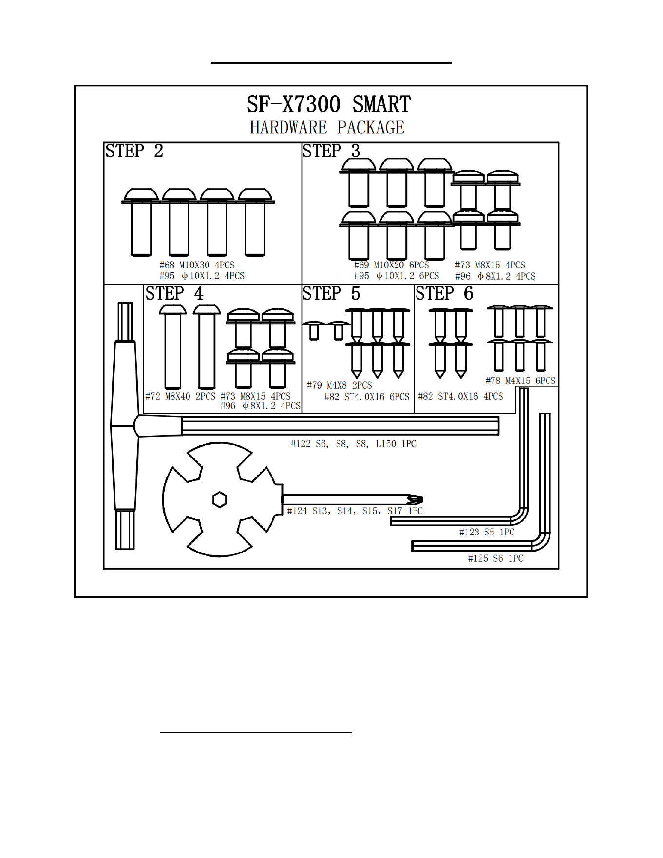
HARDWARE PACKAGE
Ordering Replacement Parts (U.S. and Canadian Customers only)
Please provide the following information in order for us to accurately identify the part(s) needed:
✓ The model number (found on cover of manual)
✓ The product name (found on cover of manual)
✓ The part number found on the “EXPLODED DIAGRAM” (page 19-20) and “PARTS LIST”
(pages 21-22)
Please contact us at [email protected] or 1-877-90SUNNY (877-907-8669).
5
ASSEMBLY INSTRUCTIONS
We value your experience using Sunny Health and Fitness products. For assistance with parts or
troubleshooting, please contact us at suppo[email protected] or 1-877-90SUNNY (877-907-
8669).
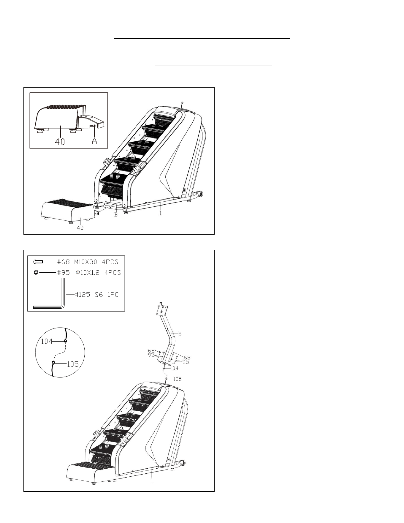
STEP 1:
We recommend having two people to do
the assembly.
Open the carton and remove contents.
Take out all parts and place the Main
Frame (No. 1) and the Pedal (No. 40) on
level ground. Ensure you have a clean and
adequate workspace.
Fasten part A of the Pedal (No. 40) (as
shown in Fig. 1) to part B of the Main
Frame (No. 1). Make sure the two parts
are centered.
STEP 2:
Connect the Console Extension Wire
(No. 104) to the Console Lower Wire (No.
105).
Secure the Console Support Post (No. 5)
on the post of the Main Frame (No. 1) with
4 Allen Bolts (No. 68) and 4 Internal
Serrated Washers (No. 95) using Allen
Wrench (No. 125).
NOTE: Please do not completely tighten
the Allen Bolts (No. 68) at this step.
NOTE: Please be careful not to drop the
Allen Bolts (No. 68) and Internal
Serrated Washers (No. 95) into the
protective cover of the Main Frame (No.
1).
Fig. 1
6
We value your experience using Sunny Health and Fitness products. For assistance with parts or
troubleshooting, please contact us at suppo[email protected] or 1-877-90SUNNY (877-907-
8669).
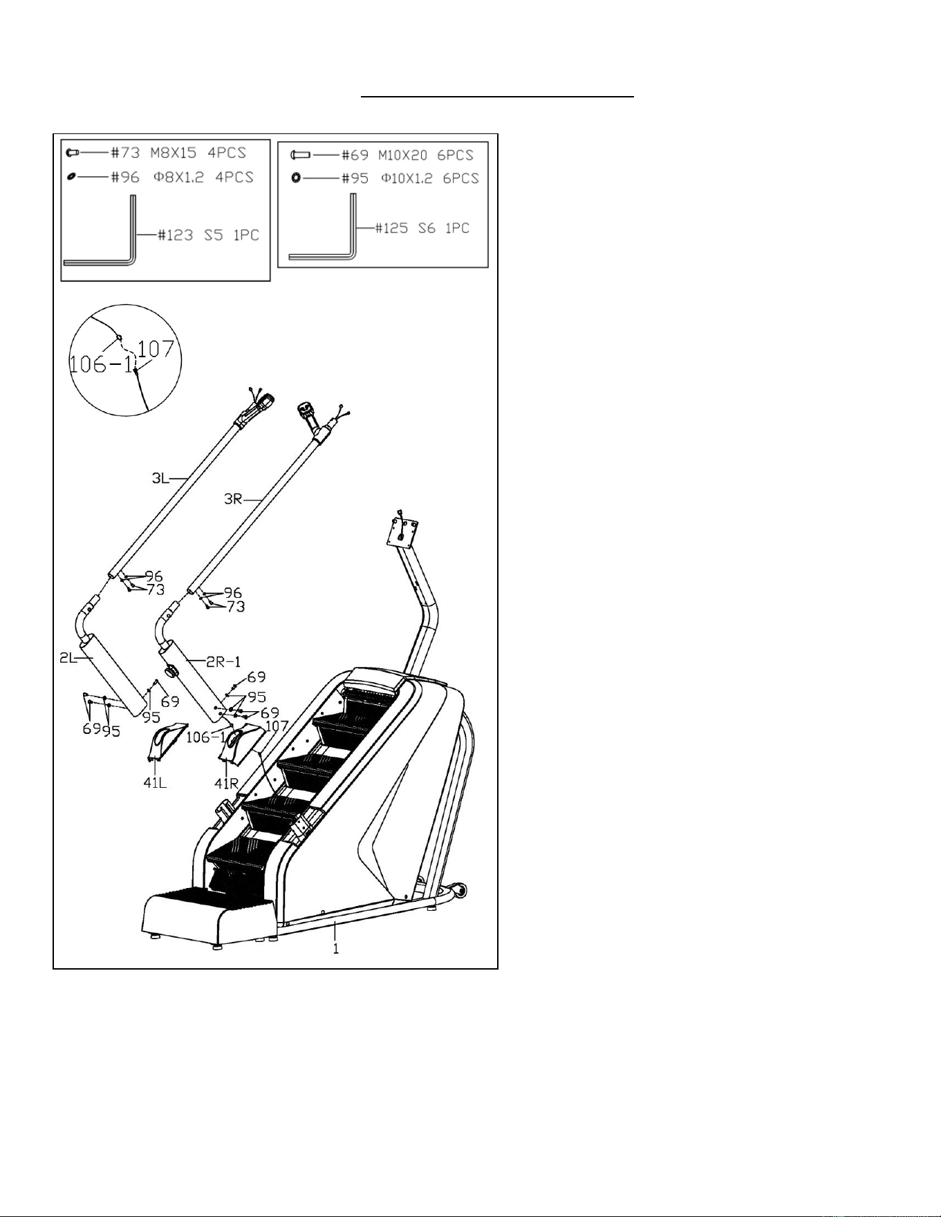
STEP 3:
Thread the Lower Switch Extension
Wire (No. 107) through the Right
Decorative Cover (No. 41R) and then
connect it with the Lower Switch Wire
(No. 106-1).
Insert the Left and Right Decorative
Covers (No. 41L & No. 41R) on the Left
and Right Support Columns (No. 2L &
No. 2R-1), then secure the Left and Right
Support Columns (No. 2L & No. 2R-1)
on the Main Frame (No. 1) with 6 Allen
Bolts (No. 69) and 6 Internal Serrated
Washers (No. 95) using Allen Wrench
(No. 125).
NOTE: Please do not completely tighten
the Allen Bolts (No. 69) at this step.
Attach the Left and Right Handrails (No.
3L & No. 3R) to the Left and Right
Support Columns (No. 2L & No. 2R-1)
with 4 Large Flat Head Bolts (No. 73)
and 4 Internal Serrated Washers (No.
96) using Allen Wrench (No. 123).
NOTE: Please do not completely tighten
the Large Flat Head Bolts (No. 73) at this
step.
7
We value your experience using Sunny Health and Fitness products. For assistance with parts or
troubleshooting, please contact us at suppo[email protected] or 1-877-90SUNNY (877-907-
8669).
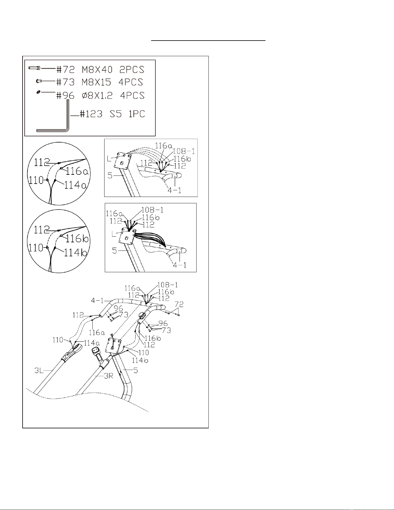
STEP 4:
Connect the 2 Pulse Extension Wires
(No. 112) with the 2 Pulse Upper Wires
(No. 110). Then connect the Keyboard
Upper Wire A (No. 114a) with Keyboard
Extension Wire A (No. 116a) and connect
the Keyboard Upper Wire B (No. 114b)
with Keyboard Extension Wire B (No.
116b).
Thread the 2 Pulse Extension Wires (No.
112), Keyboard Extension Wires A & B
(No. 116a & No. 116b) and Upper Switch
Wire (No. 108-1) through hole L on the
bracket of the Console Support Post
(No. 5). Then attach the Front Handrail
(No. 4-1) to the Left and Right Handrails
(No. 3L & No. 3R) with 4 Large Flat Head
Bolts (No. 73) and 4 Internal Serrated
Washers (No. 96) using Allen Wrench
(No. 123).
NOTE: Please do not completely tighten
the Large Flat Head Bolts (No. 73) at this
step.
Fasten the Front Handrail (No. 4-1) to the
bracket of the Console Support Post
(No. 5) with 2 Allen Bolts (No. 72) using
Allen Wrench (No. 123).
Now, fasten the 4 Allen Bolts (No. 68)
from STEP 2 tightly using Allen Wrench
(No. 125).
Then, tighten 6 Allen Bolts (No. 69) from
STEP 3 using Allen Wrench (No. 125)
and tighten 4 Large Flat Head Bolts (No.
73) from STEP 3 using Allen Wrench
(No. 123).
At last, tighten 4 Large Flat Head Bolts
(No. 73) from STEP 4 using Allen
Wrench (No. 123).
NOTE: Ensure that all bolts and washers
are in place and partially threaded in
before completely tightening them.
8
We value your experience using Sunny Health and Fitness products. For assistance with parts or
troubleshooting, please contact us at suppo[email protected] or 1-877-90SUNNY (877-907-
8669).
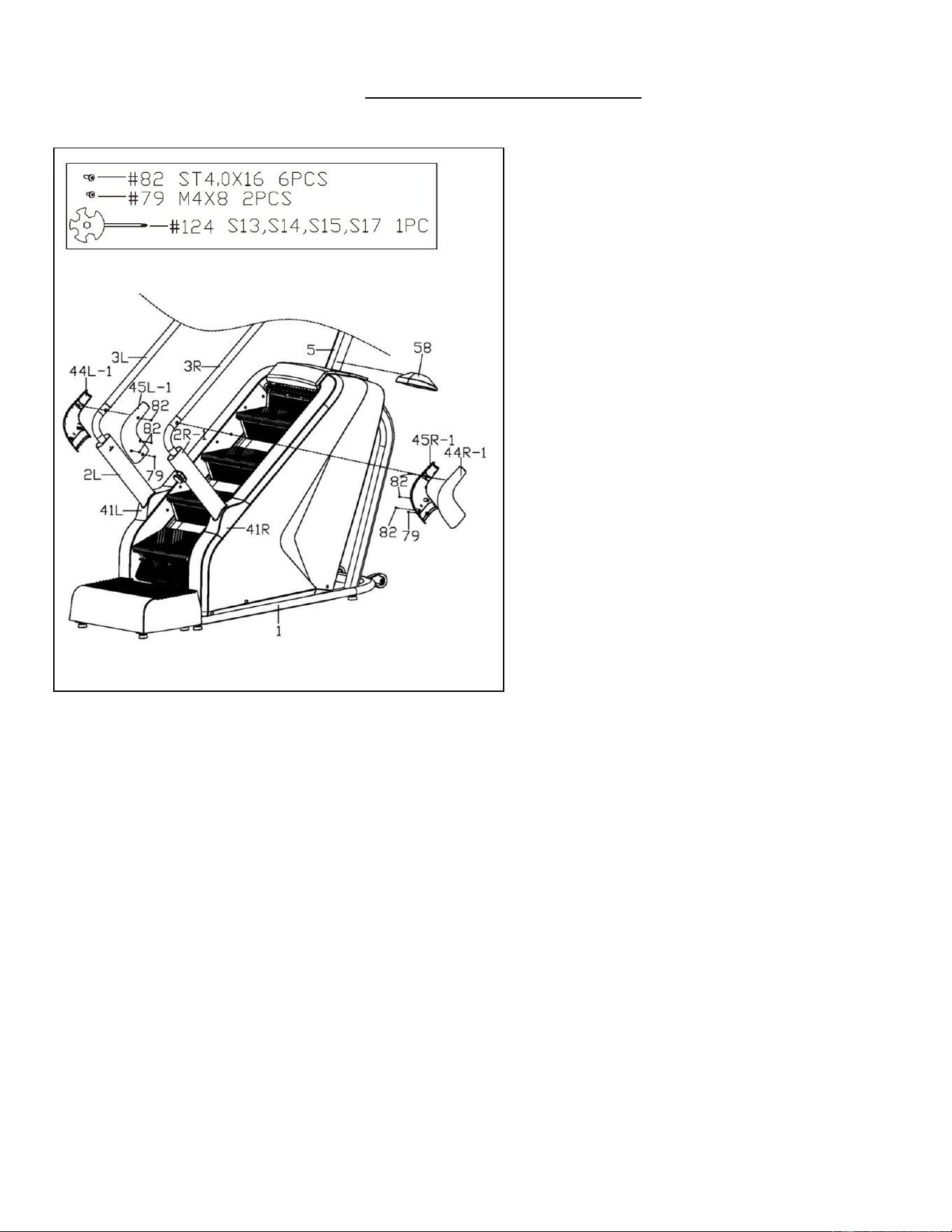
STEP 5:
Buckle the Left and Right Decorative
Covers (No. 41L & No. 41R) on the Main
Frame (No. 1) in place.
Lock the Left and Right Exterior
Decorative Covers (No. 44L-1 & No.
44R-1) and Left and Right Interior
Decorative Covers (No. 45L-1 & No.
45R-1) on the Left and Right Support
Columns (No. 2L & No. 2R-1) with 6
Phillips Tapping Screws (No. 82) and 2
Phillips Screws with Washer Head (No.
79) using Spanner (No. 124).
Attach the Decorative Cover (No. 58)
onto the Console Support Post (No. 5)
and then buckle it onto the Main Frame
(No. 1).
9
We value your experience using Sunny Health and Fitness products. For assistance with parts or
troubleshooting, please contact us at suppo[email protected] or 1-877-90SUNNY (877-907-
8669).
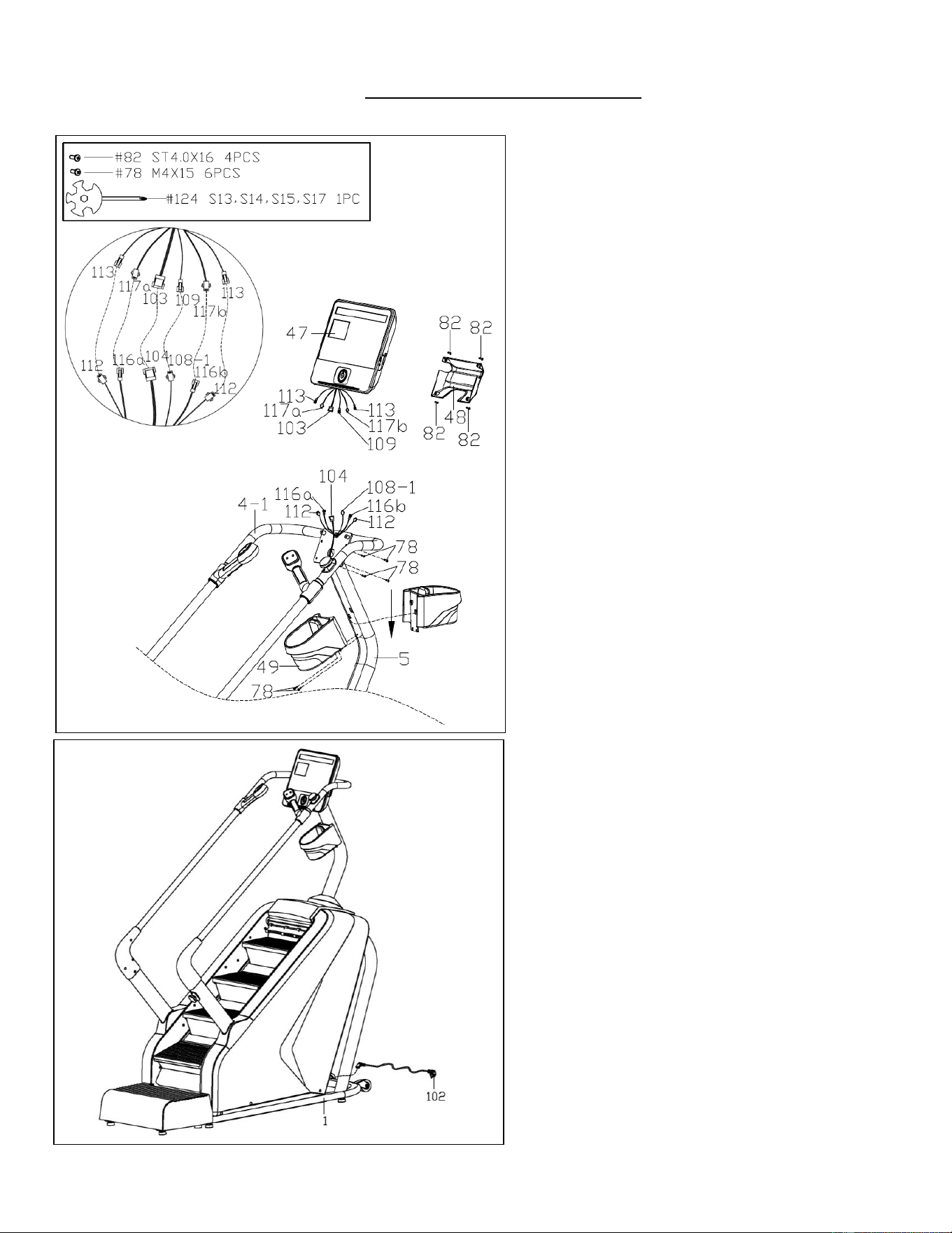
STEP 6:
Connect 2 Pulse Lower Wires (No. 113)
with 2 Pulse Extension Wires (No. 112),
connect Keyboard Extension Wire A (No.
116a) with Keyboard Lower Wire A (No.
117a), connect Keyboard Extension Wire
B (No. 116b) with Keyboard Lower Wire B
(No. 117b), connect Console Extension
Wire (No. 104) with Console Upper Wire
(No. 103), and connect Upper Switch Wire
(No. 108-1) with Upper Switch Extension
Wire (No. 109). Make sure to match the
wires by numbers as shown in Fig. 2.
Attach the Console (No. 47) to the bracket
of the Console Support Post (No. 5) with 4
Phillips Screws W/ Washer Head (No. 78).
Tighten and secure with Spanner (No. 124).
NOTE: Be careful not to cut or pinch any
wires when attaching the Console (No. 47).
Attach the Rear Decorative Cover (No. 48)
to the Console (No. 47) with 4 Phillips
Tapping Screws (No. 82). Tighten and
secure with Spanner (No. 124).
Buckle the Bottle Holder (No. 49)
downwards on the holes of the Console
Support Post (No. 5). Then lock with 2
Phillips Screws W/ Washer Head (No. 78)
using Spanner (No. 124).
STEP 7:
Insert the jack of the Power Cord (No. 102)
to the power interface on the front of Main
Frame (No. 1), then plug the Power Cord
(No. 102) into an outlet.
The assembly is now complete!
Fig. 2
10
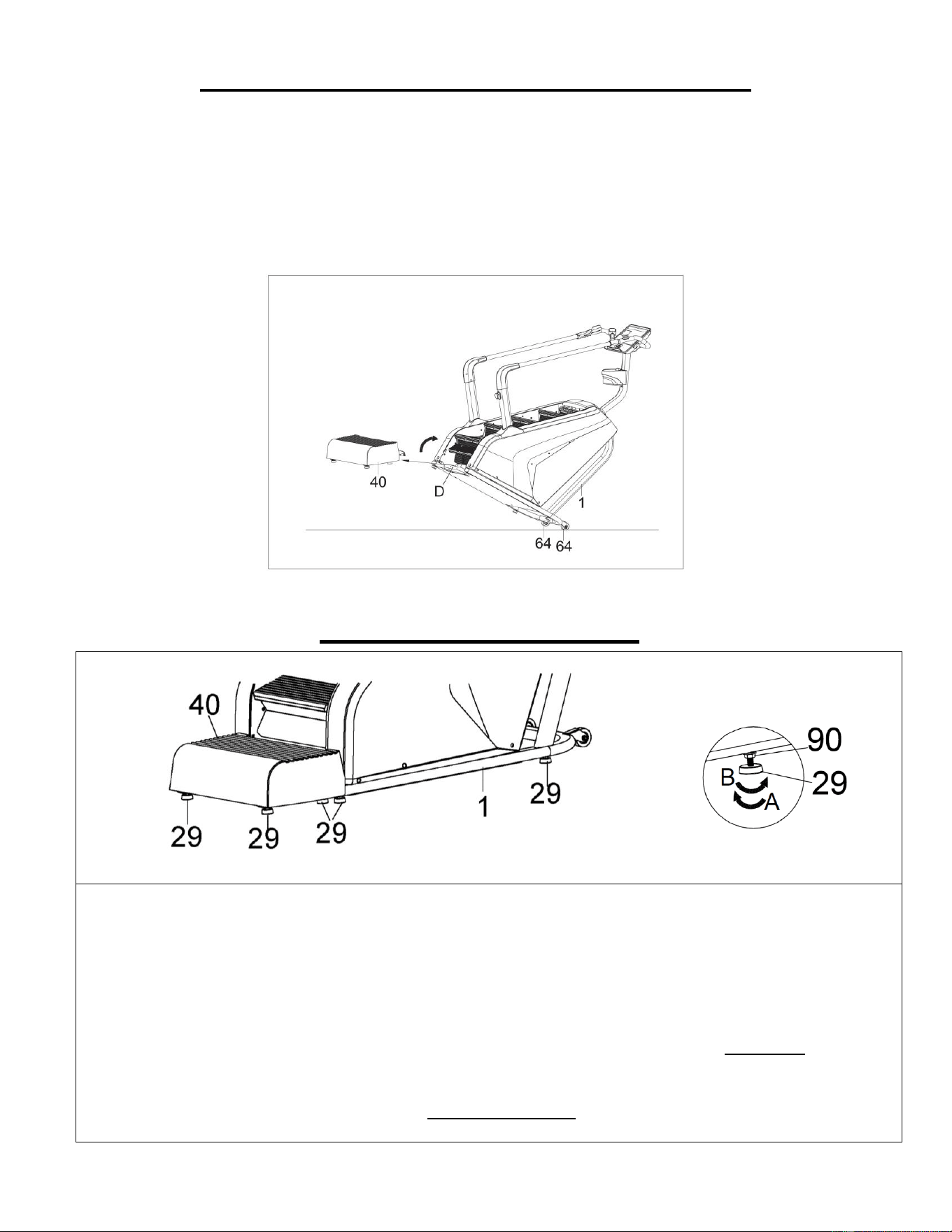
HOW TO MOVE THE STAIR CLIMBER
WARNING: Machine is very heavy, please make sure there is adequate amount of people to help
move the machine.
First, remove Pedal (No. 40). Then hold the Handlebar (No. D) of Main Frame (No. 1) and tilt the
stair climber until the Transportation Wheels (No. 64) touch the ground. With the Transportation
Wheels (No. 64) on the ground, you can move the stair climber.
ADJUSTMENT GUIDE
ADJUSTING THE BALANCE
To achieve a smooth and comfortable use, you must ensure that the stair climber is stable and
secure. If you notice that the stair climber is unbalanced during use, you should adjust the Foot
Pads (No. 29). There are a total of 8 Foot Pads (No. 29) located beneath the Main Frame (No.
1) and the Pedal (No. 40). Simply rotate the Foot Pads (No. 29) until the stair climber becomes
level with the floor surface.
To do so, loosen the Hex Nut (No. 90) on the Foot Pad (No. 29) by turning it clockwise (direction
A). With the Hex Nut (No. 90) loosened, rotate Foot Pad (No. 29) until it sits level with the
surface that the stair climber is on. When you have finished adjusting the Foot Pad (No. 29), re-
tighten the Hex Nut (No. 90) by turning it counter-clockwise (direction B). If necessary, repeat this
process to adjust the remaining Foot Pads (No. 29).
11
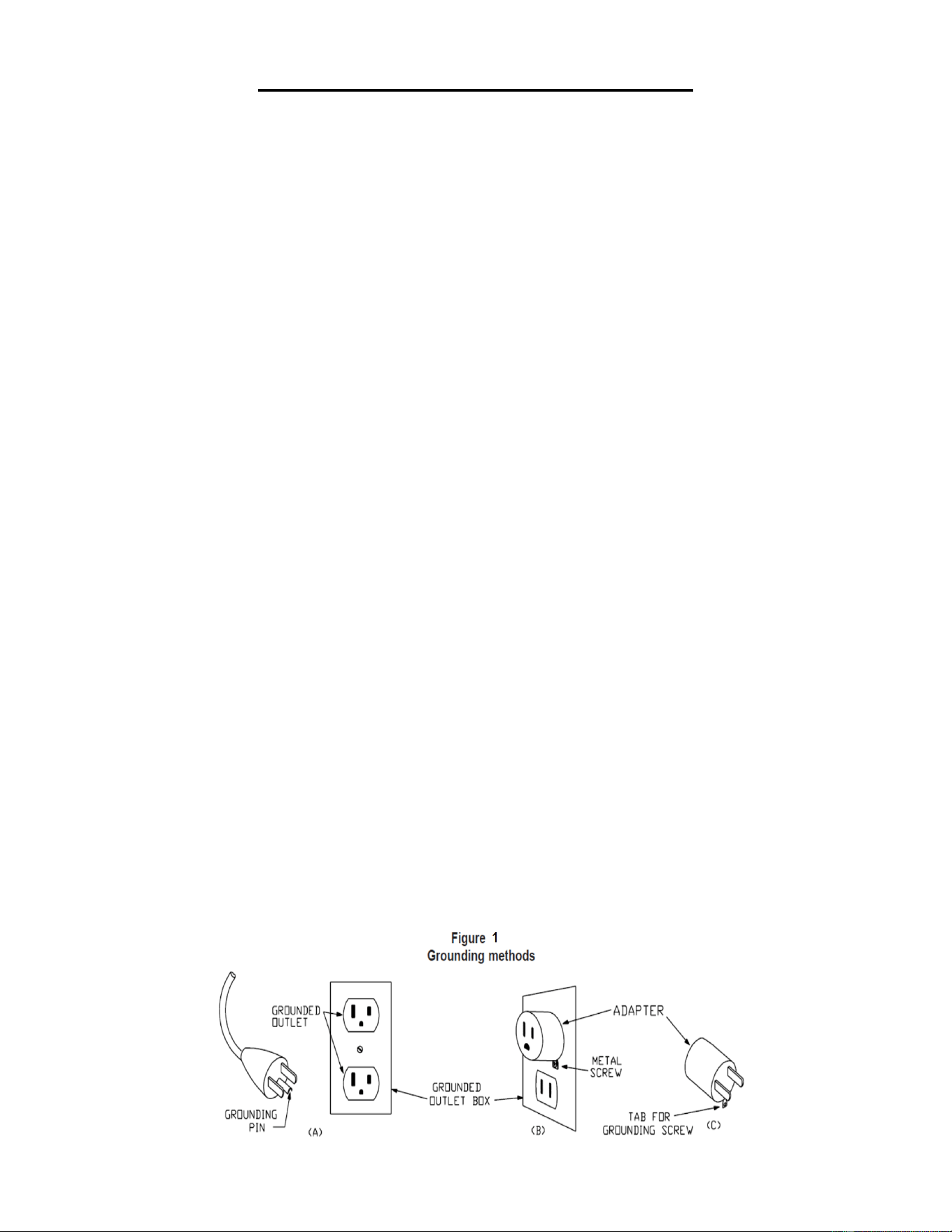
GROUNDING INSTRUCTIONS
WARNING: This stair climber requires a power source of 1A (120V) to properly operate. For
your safety, as well as the safety of others, please verify that the power source is correct before
powering the equipment. Any power source above or below this level could cause significant damage
to the equipment and/or user.
This product must be grounded. If it should malfunction or breakdown, grounding provides a path of
least resistance for electric current to reduce the risk of electric shock. This product is equipped with a
cord having an equipment-grounding conductor and a grounding plug. The plug must be plugged into
an appropriate outlet that is properly installed and grounded in accordance with all local codes and
ordinances.
DANGER – Improper connection of the equipment-grounding conductor can result in a risk of
electric shock. Check with a qualified electrician or serviceman if you are in doubt as to whether the
product is properly grounded. Do not modify the plug provided with the product – if it will not fit the
outlet, have a proper outlet installed by a qualified electrician.
For a grounded, cord-connected product rated less than 15 A and intended for use on a nominal 120-
V supply circuit, the instructions in either (1) or (2):
1) This product is for use on a nominal 120-V circuit and has a grounding plug that looks like the plug
illustrated in sketch A in Figure 1. A temporary adapter that looks like the adapter illustrated in
sketches B and C may be used to connect this plug to a 2-pole receptacle as shown in sketch B if a
properly grounded outlet is not available.
The temporary adapter should be used only until a properly grounded outlet (sketch A) can be
installed by a qualified electrician. The green colored rigid ear, lug, or the like extending from the
adapter must be connected to a permanent ground such as a properly grounded outlet box cover.
Whenever the adapter is used, it must be held in place by a metal screw.
2) This product is for use on a nominal 120-V circuit and has a grounding plug that looks like the plug
illustrated in sketch A in Figure 1. Make sure that the product is connected to an outlet having the
same configuration as the plug. No adapter should be used with this product.
WARNING!
1. NEVER use a ground fault circuit interrupt (GFCI) wall outlet with this stair climber. Route the
power cord away from any moving parts of the stair climber including the elevation mechanism
and transportation wheels.
2. NEVER operate the stair climber using a generator or UPS power supply.
2. NEVER remove any cover without first disconnecting the power cord.
3. NEVER expose the stair climber to rain or moisture. This stair climber is not designed for outdoor
use or use in any other high humidity environment.
12
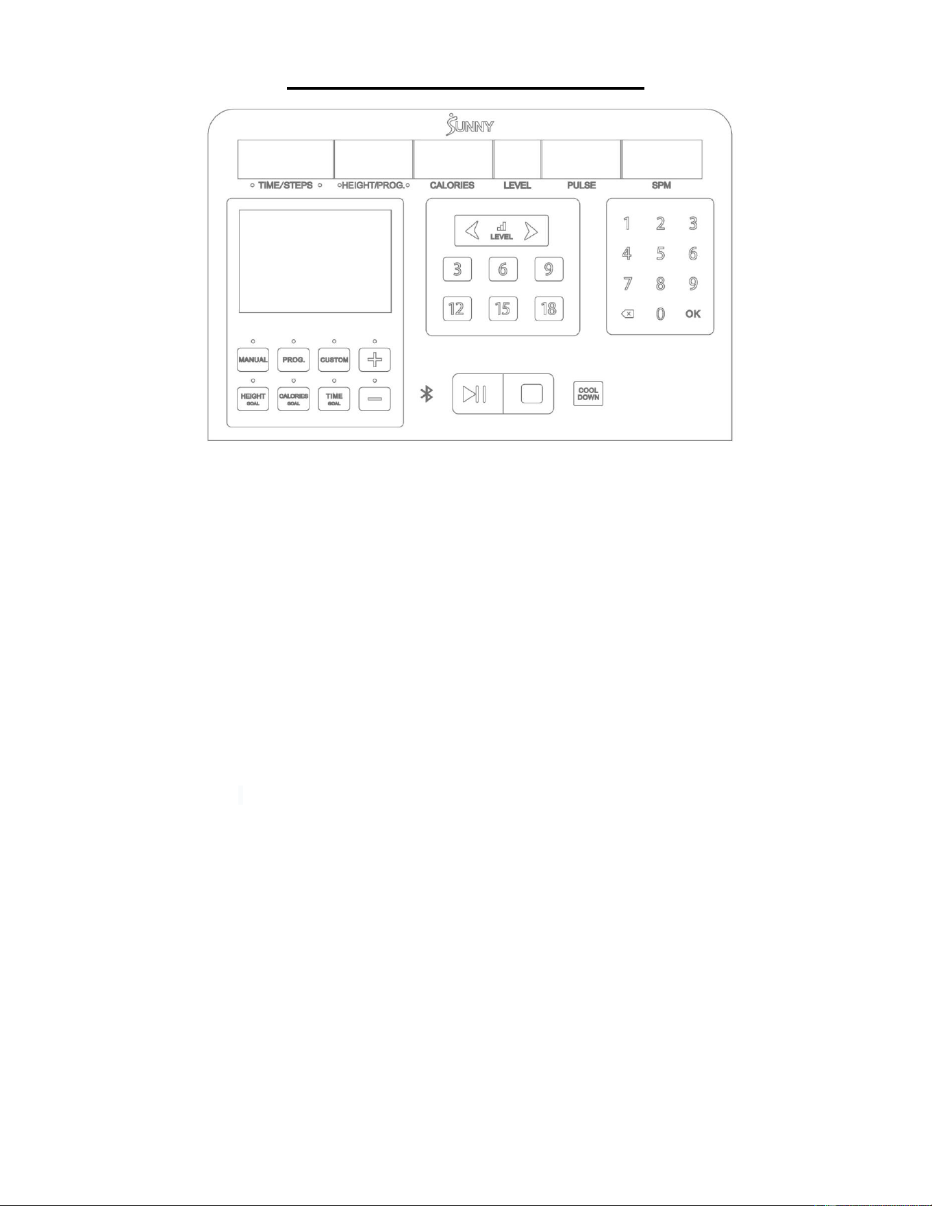
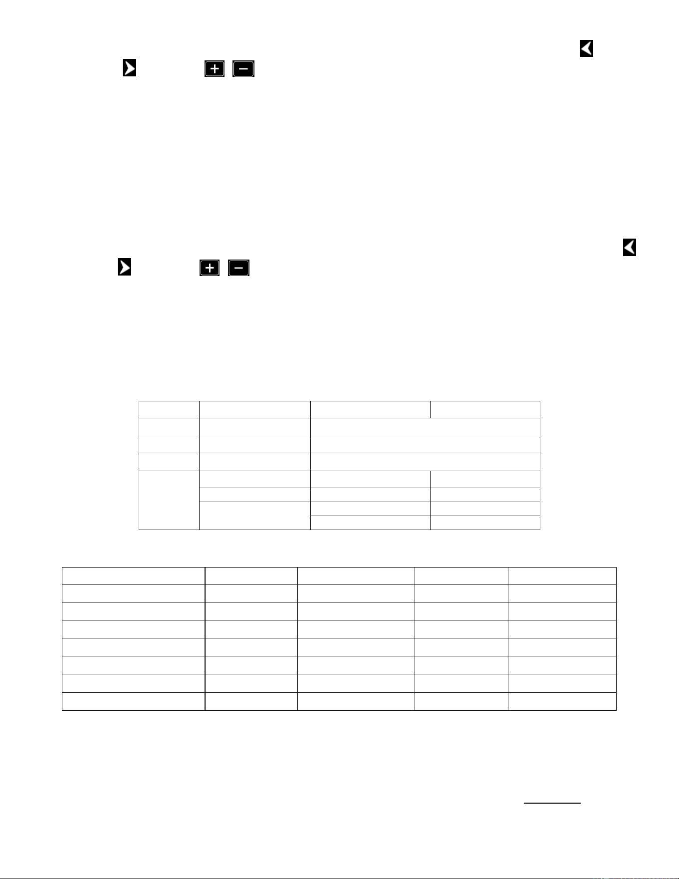
THE DISPLAY CONSOLE
1. WINDOW DISPLAY
1) “TIME/STEPS” window: Displays time duration or number of steps and will alternate every 5
seconds. When the time duration is displayed, the range is from 0:00 to 99:59. Once the time
reaches 99:59, the stair climber will slow down smoothly until it comes to a complete stop. In
goal mode, the time will countdown from the set time to zero. When the time reaches 0:00, the
stair climber will slow down smoothly until it comes to a complete stop. When the number of
steps is displayed, it will show the actual number of steps.
2) “HEIGHT/PROG” window: Displays the motion height (unit: meter) or the program sequence
number. When the motion height is displayed, the range is from 0.0~999. 1 meter is equal to 5
steps. In goal mode, the height will countdown from the set value to zero. When the height
reaches 0.0, the stair climber will slow down smoothly until it comes to a complete stop. When
program is displayed, the window will indicate the current program number or the current
segment number when in custom program.
3) “CALORIES” window: Displays the number of calories consumed, the range is from 0.0~999. In
goal mode, the calories will countdown from the set value to zero. When the calories reach 0.0,
the stair climber will slow down smoothly until it comes to a complete stop.
4) “LEVEL” window: Display speed level value, the range is 1~25.
5) “PULSE” window: Displays the heartbeat rate of the user. When the user holds the pulse
sensors or connect to SunnyFit Heart Rate Monitor (HR200), the system can automatically
detect the heartbeat rate of the user and display it in this window. The heartbeat rate range is
50~200 times/minute. (This data is for reference only and cannot be used as medical data.)
NOTE: The heart rate monitor is not included. Wireless heart rate function works with SunnyFit
Heart Rate Monitor HR200.
6) “SPM” window: Displays the stair climber operation speed.
7) “MAIN” window: In program and custom mode, this window displays program diagram. In other
modes, this window displays floor progress and count (1 floor is every 3.5m).
2. KEY FUNCTION
1) "MANUAL/PROG/CUSTOM" allows user to select standby mode, program mode and custom
mode. Use the MANUAL key to select standby mode. Use the PROG key to select fixed
programs. Use the CUSTOM key to select custom programs. In this mode, press the “OK” key
on the number keypad to enter the setting of the custom program. You can quickly set the
parameters with the "+/-" keys during this period.
13
2) "HEIGHT GOAL/CALORIES GOAL/TIME GOAL" is the countdown mode for the selected goal.
Use the TIME GOAL key to enter time countdown mode. Use the HEIGHT GOAL to enter
height countdown mode. Use the CALORIES GOAL key to enter calories countdown mode.
You can quickly set countdown parameters with the "+/-" keys during the setting state of PROG
/CUSTOM/HEIGHT GOAL/CALORIES GOAL/TIME GOAL (except MANUAL mode).
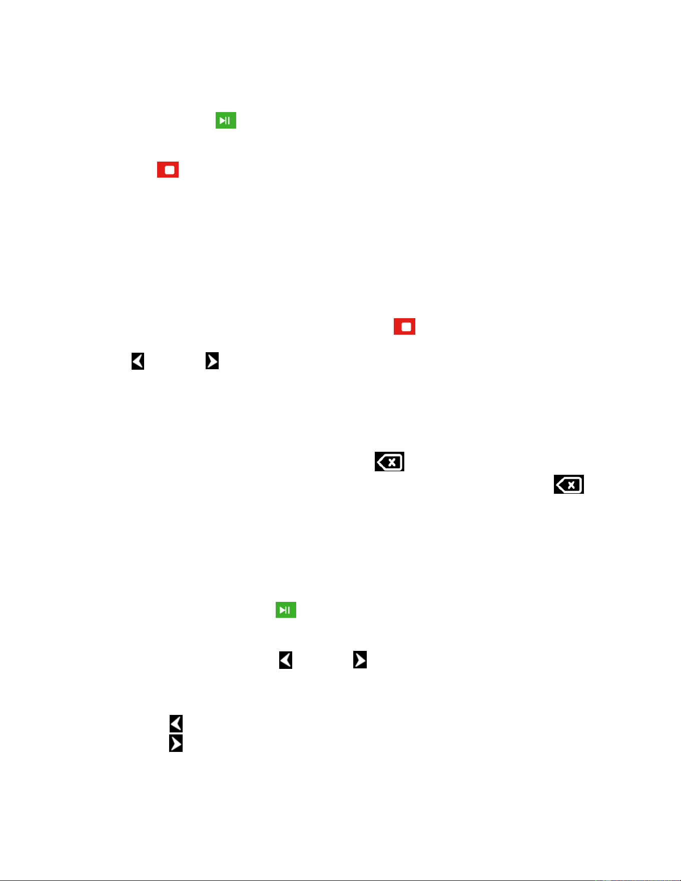
3) "START /PAUSE" key : First, make sure the two Emergency Stop Switches (No. 50) are
in pop-out state and the infrared sensing area is free of obstructions. Then, press this key at
any time to start the stair climber, or press this key to pause the stair climber during operation.
4) “STOP” key : During exercise, press this key to stop the stair climber and all values will
reset to zero. In the STOP state, press and hold the STOP key for 6 seconds to disconnect the
heart rate monitor. To reconnect the heart rate monitor, press and hold the STEP key for 6
seconds again.
5) ”COOL DOWN” key: Press this key during exercise and the stair climber will enter into the
countdown mode, the level decreases evenly and the stair climber will stop when the
countdown ends. The duration of the countdown is determined by the current exercise level
value (non-set). When the level is 1~15, press this key and the level will drop to 0 within 30
seconds, and the array window will display a 30-second countdown. When the level is 16~25,
press this key and the level will drop to 0 within 45 seconds, and the array window will display
a 45-second countdown. You can press “STOP” key to end the ”COOL DOWN”
immediately.
6) “LEVEL / LEVEL ” keys:During the setting state, use these keys to adjust the set value.
During exercise, these keys are used to adjust the level, the value will adjust by 1 each time.
The value will increase or decrease continuously if you press and hold the key for more than
0.5 seconds.
7) “LEVEL:3、6、9、12、15、18” key: These keys are level shortcut keys. During exercise,
press to quickly set desired level.
8) “Number keypad (1、2、3、4、5、6、7、8、9、 、0、OK)”: In climbing or setting state,
press the keypad number key to quickly set the parameter value. The delete key clears
the input value. The “OK” key sets the parameter to the input value. Always press “OK” key to
confirm the setting after parameters are set. If the input value exceeds the set range, the
console will automatically be set to the maximum or minimum value.
3. QUICK START (MANUAL MODE)
1) Turn on the power switch, make sure the two Emergency Stop Switches (No. 50) are in pop-
out state and the infrared sensing area is free of obstructions.
2) Press the "START /PAUSE" key , the MAIN window will display a 3-seconds countdown
and a buzzer will sound at the same time. After the 3-seconds countdown, the stair climber
starts climbing at a speed of level 1.
3) During exercise, use the "LEVEL / LEVEL ” keys, the level shortcut keys 3, 6, 9, 12, 15,
18, or number keypad keys to adjust the speed of the stair climber as needed.
4. OPERATION DURING THE MOVEMENT PROCESS
1) Press "LEVEL ” key to increase the climbing speed of the stair climber.
2) Press “LEVEL ” key to decrease the climbing speed of the stair climber.
3) Press the number keypad keys to set the stair climber speed quickly.
4) Press “STOP” key to slow down and stop climbing.
5) Press “START/PAUSE” key to start or slow down and pause climbing.
6) The pulse data is displayed for about 3 seconds when the user holds the pulse sensors with
both hands.

14
5. MANUAL MODE
1) Manual mode is the default mode when the stair climber is powered on. The MAIN window will
display floor progress and the level window will display the default level “1”.
2) Press the “START/PAUSE” key, the stair climber will start to climb at the initial speed of level 1
after a 3-seconds countdown. Press the "LEVEL / LEVEL ”, level shortcut keys, or
number keypad keys to adjust the speed.
6. GOAL MODE
1) In the standby state, press the "TIME GOAL" key to enter the time countdown mode. The
"TIME" window will display "15:00" and blink. Press the "LEVEL / LEVEL ” key, "+/-" keys
or number keypad keys to set the countdown time, which ranges from 5:00 to 99:00.
2) In the standby state, press the "HEIGHT GOAL" key to enter the height countdown mode. The
"HEIGHT" window will display "10.0" and blinks. Press the "LEVEL / LEVEL ” key, "+/-"
keys or number keypad keys to set the countdown height, which ranges from 5.0 to
999.
3) In the standby state, press the "CALORIES GOAL" key to enter the calories countdown mode.
The "CALORIES" window will display "50.0" and blinks. Press the "LEVEL / LEVEL ”
key, "+/-" keys or number keypad keys to set the countdown calories, which ranges
from 10.0~999.
4) Select one of the three goal modes and press the “START/PAUSE” key after the setting is
completed. The stair climber will start to climb after a 3-second countdown. Press the "LEVEL
/ LEVEL ”, level shortcut keys, or number keypad keys to adjust the speed.
7. PROGRAMS
1) This system has a total of 36 built-in programs P01~P36. In the standby state, press the
"PROG" key, the “HEIGHT/PROG” window will display “P01, P02, ~…P36”, select the program,
the "TIME" window will display preset time 10:00.
2) Press "LEVEL / LEVEL ” key, "+/-" keys or number keypad keys to set the
desired exercise time. Only TIME can be adjusted.
3) Press “START/PAUSE” key to start the program and the speed will gradually increase to the
value for the first segment of program (see details in the table of program parameters).
4) Each built-in program is divided into 20 segments, each segment of exercise time = set time /20.
Each operating time period has a corresponding pre-set speed.
5) When entering the next segment, the console will beep 3 times.
6) The speed changes according to the program segments. During a segment, you can press
"LEVEL / LEVEL ” key, level shortcut keys or number keypad keys to adjust speed level.
When the program enters the next segment, the speed level will return to the pre-set speed
value of that segment.
7) After the whole program is completed, the console will beep 3 times. The stair climber will slow
down until it comes to a complete stop and the MAIN window will display "End". The stair
climber will go into standby state after 5 seconds.

15
8. PROGRAM SPECIFICATION
PROGRAM SCHEDULE
SEG
Program
S
1
S
2
S
3
S
4
S
5
S
6
S
7
S
8
S
9
S1
0
S1
1
S1
2
S1
3
S1
4
S1
5
S1
6
S1
7
S1
8
S1
9
S2
0
P1
4
5
5
6
6
7
7
7
7
7
7
7
7
7
7
6
6
5
5
1
P2
4
5
5
6
7
7
10
7
10
10
10
7
10
10
7
7
6
5
5
1
P3
4
5
5
6
7
7
10
10
7
10
10
10
10
7
7
7
6
5
5
1
P4
4
5
5
6
6
9
9
9
9
9
9
12
9
9
9
6
6
5
5
1
P5
4
5
5
6
7
9
9
9
9
12
9
9
9
9
9
7
6
5
5
1
P6
4
5
5
7
7
9
9
12
12
12
12
9
9
9
9
9
7
5
5
1
P7
4
5
6
8
8
11
11
11
11
11
11
11
11
11
11
11
8
6
6
2
P8
4
5
5
7
7
10
10
10
10
12
12
12
12
12
12
12
12
12
11
5
P9
4
5
5
8
8
11
11
11
9
11
11
11
11
11
11
11
8
5
5
2
P10
4
5
5
7
7
9
5
7
7
9
5
7
7
9
5
7
7
9
7
3
P11
4
6
6
8
8
11
6
8
8
11
6
8
8
11
6
8
8
11
6
1
P12
4
6
6
9
12
12
6
9
12
12
6
9
12
12
6
9
12
12
9
4
P13
4
9
4
9
4
9
4
9
4
9
4
9
4
9
4
9
4
9
4
9
P14
4
5
5
8
11
11
5
8
11
11
5
8
11
11
5
8
11
11
8
3
P15
4
6
9
9
9
6
9
9
9
6
9
9
9
6
9
9
9
6
4
2
P16
4
6
6
11
6
11
6
11
6
11
6
11
6
11
6
11
6
11
6
9
P17
4
4
4
6
8
8
11
11
11
4
6
8
8
11
11
11
8
4
4
2
P18
5
8
5
8
8
5
8
8
5
8
8
5
8
8
5
8
8
4
4
2
P19
4
9
4
9
4
9
4
9
4
9
4
9
4
9
4
9
4
9
4
2
P20
4
12
4
12
4
12
4
12
4
12
4
12
4
12
4
12
4
12
4
4
P21
4
8
4
8
11
4
8
11
4
8
11
4
8
11
4
8
11
4
8
2
P22
6
8
11
8
4
11
8
4
11
8
4
11
8
4
11
8
4
4
6
2
P23
6
8
11
8
8
4
11
8
8
4
11
8
8
4
11
8
8
4
4
2
P24
6
8
11
8
6
11
8
6
11
8
6
11
8
6
11
8
6
4
6
2
P25
4
6
5
6
5
7
6
4
7
4
8
4
9
4
10
5
9
5
11
3
P26
4
7
6
8
6
8
6
4
6
5
5
8
7
9
7
9
7
5
7
2
P27
4
7
6
7
6
7
6
4
5
5
5
8
7
8
7
8
7
5
6
2
P28
4
8
9
6
6
9
6
4
6
5
5
9
10
7
7
10
7
5
7
2
P29
4
6
8
10
9
10
8
4
5
5
5
7
9
11
10
11
9
5
6
2
P30
4
6
7
7
8
7
8
5
5
5
5
7
8
8
9
8
9
6
6
2
P31
5
8
9
7
10
7
11
8
6
4
6
9
10
8
11
8
11
9
6
3
P32
4
7
8
6
9
7
8
7
5
5
5
8
9
7
10
8
9
8
6
3
P33
4
10
8
6
7
11
9
7
6
6
5
11
9
7
8
11
10
8
7
3
P34
4
5
7
5
5
7
5
8
5
6
5
6
8
6
6
8
6
9
6
3
P35
4
7
10
11
8
11
7
5
4
5
5
8
11
11
9
11
8
6
5
2
P36
4
7
7
6
6
8
6
4
5
7
5
8
8
7
7
9
7
5
6
4
9. CUSTOM PROGRAM
In addition to the built-in programs, the stair climber also has 3 custom programs U01, U02 and
U03 for users to set their own training program. Each program will have 20 segments.
1) In standby state, press the "CUSTOM" key to select the desired custom program (U01, U02 or
U03). The "TIME" window will flash the preset time: 10:00. Press "+/-" , "LEVEL /
LEVEL ” key, or number keypad keys to adjust the time.
2) Press the “OK” key to confirm the time setting and enter to set the speed level for each
16
segment. “HEIGHT/PROG” window will flash S01 for the 1st segment. Press "LEVEL /
LEVEL ” key, "+/-" or number keypad keys to set the speed level and press “OK”
key to confirm. Repeat to set the speed for the remaining 19 segments.
3) After the setting is complete, the data will be permanently saved until you reset the next time,
and it will not be lost due to power failure.
4) The speed and climbing time of all 20 time periods must be set before starting the custom
program.
10. BODY MASS INDEX
In the standby state, continuously press the "PROG" key 37 times to enter the Body Mass Index
(FAT) detection function. The “HEIGHT/PROG” window will display “FAT”, press the "OK" key to
enter into F-1. Then press "OK" key or "PROG" key to quickly switch to F-2, F-3, F-4, F-5
interface (F-1: gender, F-2: age, F-3: height, F-4: weight, F-5: physical test). Press the "LEVEL
/ LEVEL ” key, "+/-" or number keypad keys to set the parameters of F-1 through F-4
(parameters are in the following table). After setting is complete, enter the F-5 physical detection
interface. At this time, hold the heartrate sensors with both hands for 2-3 seconds, your Body
Mass Index (FAT) will be displayed to check whether your weight and height are commensurate.
Body Mass Index (FAT) is a measure of a person's height and weight, not body proportion. FAT is
suitable for any man or woman, along with other health indicators, it provides a basis for people to
adjust their weight. The ideal FAT should be between 20 and 25, with anything below 19 being too
thin, anything between 25 and 29 being overweight, and anything above 30 being obese. (This
data is for reference only and should not be considered as medical data).
F-1
Gender
01 (man)
02(woman)
F-2
Age
10------99
F-3
Height
100-200 (cm)
F-4
Weight
20-150 (kg)
F-5
FAT
≤19
Underweight
FAT
=(20---25)
Normal weight
FAT
=(26---29)
Overweight
FAT
≥30
Obese
11. DISPLAY RANGE FOR EACH VALUE
Set Parameters
Initial Value
Initial Set Value
Setting Range
Display Range
TIME (minute:second)
0:00
15:00
5:00~99:00
0:00~99:59
Level
1
1
1~25
1~25
STEPS (step count)
0
N/A
N/A
0~9999
HEIGHT (meter)
0.0
10.0
5.0~999
0.0~999
PULSE (times/min)
P
N/A
N/A
50~200
CALORIES (KCAL)
0.0
50.0
10.0~999
0.0~999
SPM (Revolution)
0
N/A
N/A
0~999
12. EMERGENCY STOP FUNCTION
In any mode, the Emergency Stop Switch (No. 50) can be pressed to stop the stair climber. The
stair climber will come to an immediate stop and all windows will display "--", the console will beep
3 times and the MAIN window display “SAFETY STOP BUTTON ACTIVATED-TWIST
EMERGENCY STOP BUTTON TO UNLOCK”. At this time, the stair climber cannot perform any
other operation except shutdown. Turn the Emergency Stop Switch (No. 50) clockwise, the stair
climber will go back to the standby state, waiting input instructions.
17
13. POWER SAVING MODE
This console has a power saving function. In the standby state, if there is no key input for 10
minutes when Bluetooth is not connected, the console will enter power saving mode, and
automatically closes the display. Press any key to wake the system.
14. WIRELESS CHARGING FUNCTION
Wireless charging can be used to charge mobile phones with wireless charging function.
15. POWER OFF
You can turn off the stair climber at any time by turning off the power switch, which does not
damage the stair climber.
16. PRECAUTIONS
1) Check the power supply before exercise.
2) If there is an abnormal situation during exercise, press the Emergency Stop Switch (No. 50)
to stop the stair climber.
3) Non-professional personnel should not disassemble or attempt to repair the equipment, to
avoid damage.
4) During operation, the stair climber will stop immediately if any object is detected in the infrared
sensing area, and main window display “PRESS ANY BUTTON TO UNLOCK”, “CALORIES”
window display “E08”. Remove the object, then press any button to unlock the alarm
interface.
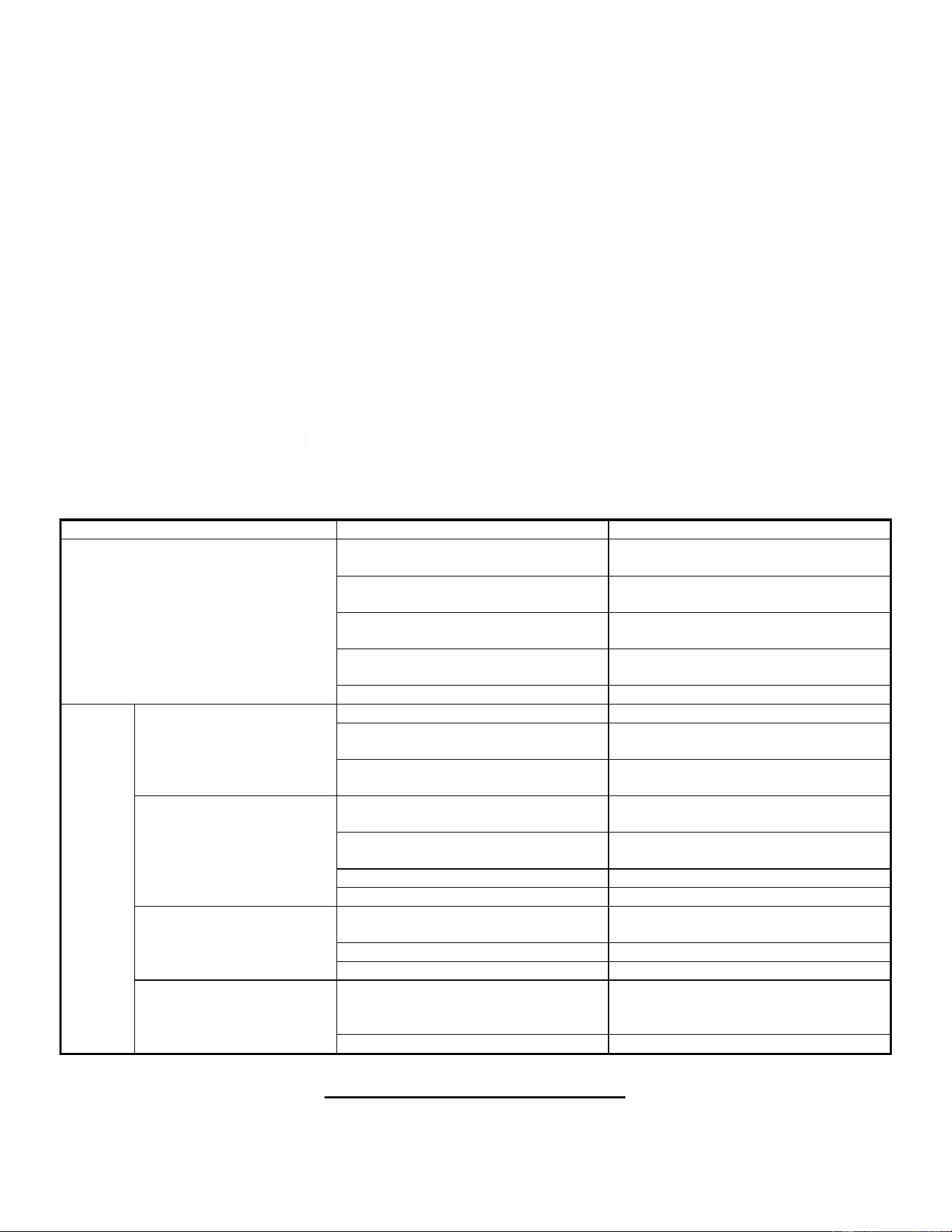
17. TROUBLESHOOTING
Error
Possible Reasons
Solution
Machine has no display.
1. Not plugged in, or no power.
Connect the power cord to the AC
socket or check the AC socket.
2. Power switch is not turned on.
Set the power switch to the ON
position.
3. Controller is without power or
damaged.
Replace Controller.
4. Console wires are disconnected.
Replace the console wires and plug
them in again.
5. Console is damaged.
Replace the computer
Console
display
---or----
1. The scram switch was pressed.
Turn the scram switch clockwise
2. Scram switch cable disconnected
Check whether the scram cable is
plugged properly.
3. Emergency Stop Switch (No.
50) is damaged.
Replace the Emergency Stop Switch
(No. 50).
E80/E01-Communication
failure (the driver does not
receive the console signal)
E02-Communication
failure (no driver signal is
received by the console).
1. Console wires are not connected
or poor connected
Re-connect the console wires.
2. The console wires are damaged,
short circuit or open circuit.
Replace the console wires.
3. Console signal circuit fault.
Replace the console.
4.Driver signal circuit fault.
Replace the driver.
E08-Lower control infrared
fault.
1.The infrared detection at the end of
the stair climber is blocked.
Remove blocked foreign objects.
2.Infrared sensor fault.
Replace the sensor.
3.Controller failure
Replace the controller.
E48-No speed sensing
signal (with speed sensing
driver).
1.The speed signal line is not
connected, or the sensor is
damaged.
Reinsert the speed signal line or
replace the sensor.
2.The driver sensor line is faulty.
Replace the driver.
NOTE: If you are unable to resolve an issue using the troubleshooting guide above, please
contact Customer Service at [email protected]

18
TECHNICAL DATA
Connectivity: Bluetooth LE
Frequency Range: 2400~2483.5 Mhz
Transmitting Power: 0 dBm
APP CONNECTION:
Connect Smart Equipment to SunnyFit App:
1. Scan to download SunnyFit from the app store:
2. Ensure that the Bluetooth function is turned on from your mobile device.
3. If this is your first time using the SunnyFit app, follow the in-app instructions to register for your
free SunnyFit account and log in.
4. Begin any workout activity that matches your smart equipment, then follow the onscreen
prompts to search for and connect to your smart equipment.
5. When connected, your stats and records will be displayed at the end of your course/session,
and recorded in your account profile!
Troubleshooting:
•
If you are having trouble connecting your smart equipment, visit www.sunnyfit.com/guide or
scan the QR code below:
•
If you require additional support, please contact [email protected].
19
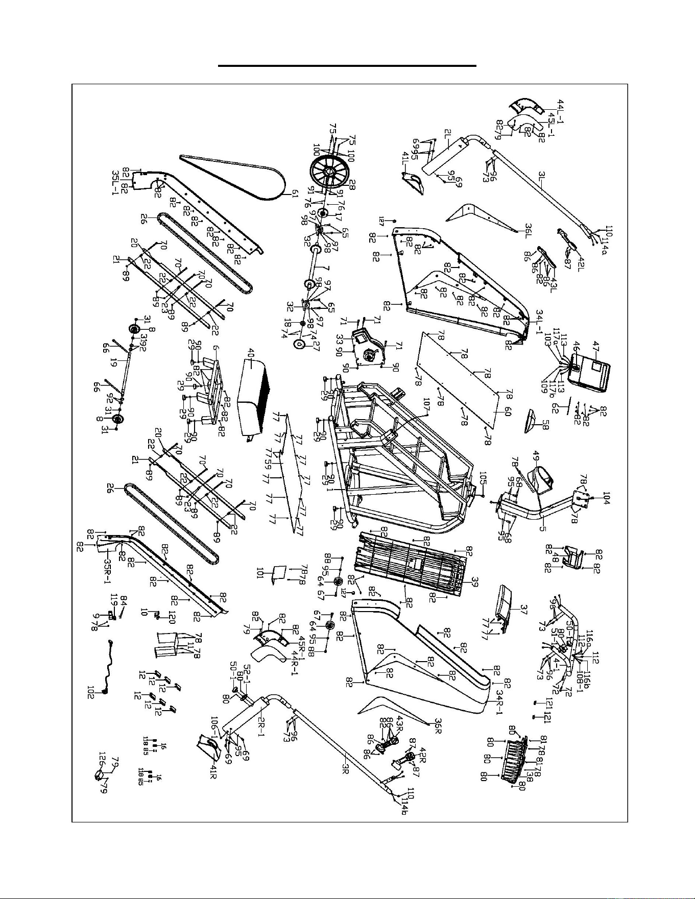
EXPLODED DIAGRAM 1
20
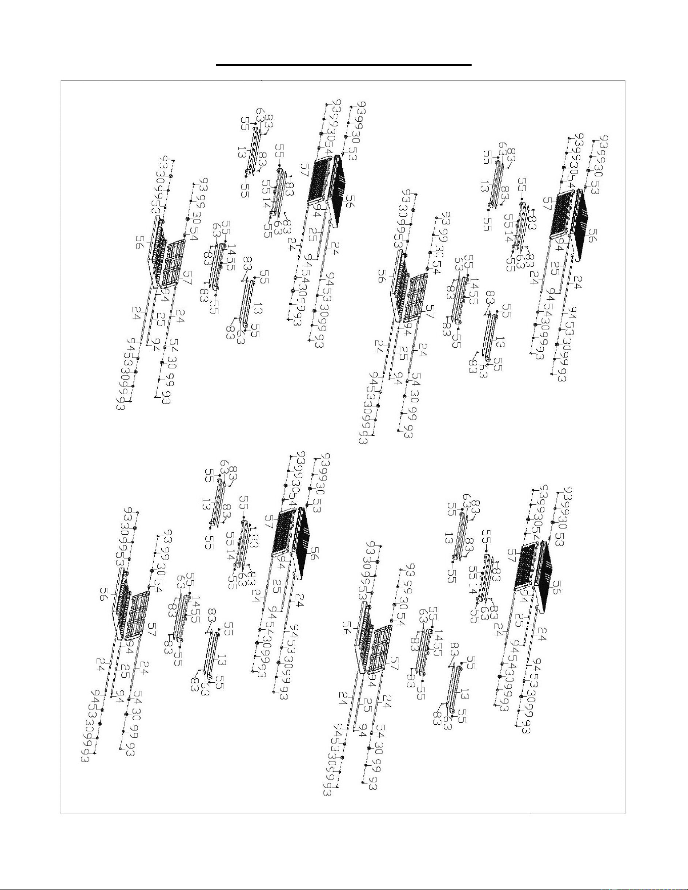
EXPLODED DIAGRAM 2

21
PARTS LIST
No.
Description
Specification
Qty.
No.
Description
Specification
Qty.
1
Main Frame
1
34R-1
Right Protective Cover
1309X1133X202
1
2L
Left Support Column
1
35L-1
Left Inner Protective
Cover
1005.6X1091X47.
5
1
2R-1
Right Support
Column
1
35R-1
Right Inner Protective
Cover
1005.6X1091X47.
5
1
3L
Left Handrail
1
36L
Left Decorative Strip
355.6X646.6X18
1
3R
Right Handrail
1
36R
Right Decorative Strip
355.6X646.6X18
1
4-1
Front Handrail
1
37
Upper Protective Cover
460X233X100.6
1
5
Console Support
Post
1
38
Upper Protective Cover
2
649X186.6X153.5
1
6
Rear Bracket
1
39
Rear Cover
1013X600X45
1
7
Front Roller
1
40
Pedal
773X528X173
1
8
Rear Gear
2
41L
Left Decorative Cover
248X135.6X98.4
1
9
Sensor Fix Tube
125X40X2.0
1
41R
Right Decorative Cover
248X135.6X98.4
1
10
Light Sensor
Support
92.3X22X2.5
1
42L
Left Upper Cover
1
11
PCB Baffle
617X100X2.0
1
42R
Right Upper Cover
1
12
Fixing Plug
60.8X65X2.0
6
43L
Left Lower Cover
1
13
Stair Support 1
8
43R
Lower Cover
1
14
Stair Support 2
8
44L-1
Left Exterior Decorative
Cover
1
15
N/A
-
44R-1
Right Exterior
Decorative Cover
1
16
Fixing Cover
54X30X3.0
2
45L-1
Left Interior Decorative
Cover
1
17
Pulley Shaft Sleeve
Φ98X33
1
45R-1
Right Interior
Decorative Cover
1
18
Emergency Stop
Disk Sleeve
Φ45X15
1
46
Wireless Charge
Module
1
19
Rear Roller Shaft
Φ20X670
1
47
Console
15.6 inches
1
20
Guide
1065X45X6.0
2
48
Rear Decorative Cover
1
21
Guide 2
1060X53X6.0
2
49
Bottle Holder
1
22
Support Sleeve 1
Φ14XΦ8.2X22.8
8
50-1
Emergency Stop
Switch
2
23
Support Sleeve 2
Φ14XΦ8.2X22.2
2
51-1
Switch Base 1
78X38.4X19
1
24
Bearing Connecting
Shaft
Φ7.9X586
16
52-1
Switch Base 2
82X42X18
1
25
Step Connecting
Shaft
Φ7.9X505
8
53
Step Spacer 1
Φ15XΦ8.0X12.5
16
26
Chain
L2438.4mm
2
54
Step Spacer 2
Φ15XΦ8.0X17.9
16
27
Emergency Stop
Plate
105X1.0
1
55
Wear Washer
Φ15X4.7
40
28
Belt Pulley
Φ360X26
1
56
Pedal 1
501X245X52.5
8
29
Foot Pad
Φ46X17
8
57
Pedal 2
490X126.7X20
8
30
Bearing
608Z
32
58
Decorative Cover
275.7X146.6X70.4
1
31
Bearing
6004
4
59
Bottom Baffle
870X690X3.0
1
32
Pedestal Bearing
KP005
2
60
Middle Baffle
1025.6X554X28
1
33
Brake Combination
1
61
Belt
J900
1
34L-
1
Left Protective
Cover
1309X1133X202
1
62
Anti Slip Pad
446.5X13X2.0
1

22
No.
Description
Specification
Qty.
No.
Description
Specification
Qty.
63
Eva Pad
485X36X2.0
16
97
Standard Spring Washer
Φ10
4
64
Transportation
Wheel
Φ75 X26
2
98
Standard Flat Washer
Φ10
4
65
Allen Bolt
M10X40
4
99
Flat Washer
Φ8
32
66
Allen Bolt
M10X170
2
100
Flat Washer
Φ6
4
67
Outer Hexagon Bolt
M10X45
2
101
Controller
1
68
Allen Bolt
M10X30
4
102
Power Cord
2000MM
1
69
Allen Bolt
M10X20
6
103
Console Upper Wire
300MM
1
70
Allen Bolt
M8X105
10
104
Console Extension Wire
1200MM
1
71
Allen Bolt
M8X75
3
105
Console Lower Wire
2200MM
1
72
Allen Bolt
M8X40
2
106-1
Lower Switch Wire
600MM
1
73
Large Flat Head Bolt
M8X15
8
107
Lower Switch Extension
Wire
1600MM
1
74
Flat End Tightening
M4X5
3
108-1
Upper Switch Wire
950MM
1
75
Allen Bolt
M6X25
4
109
Upper Switch Extension
Wire
300MM
1
76
Flat End Tightening
M5X10
3
110
Pulse Upper Wire
350MM
2
77
Phillips Tapping
Screw W /Washer
Head
ST4.0X12
16
111
N/A
78
Phillips Screw W/
Washer Head
M4X15
24
112
Pulse Extension Wire
1000MM
2
79
Phillips Screw W/
Washer Head
M4X8
4
113
Pulse Lower Wire
300MM
2
80
Phillips Countersunk
Screw
M4X10
9
114a
Keyboard Upper Wire A
400MM, Red
1
81
Phillips Countersunk
Screw
ST4.0X16
2
114b
Keyboard Upper Wire B
400MM, Green
1
82
Phillips Tapping
Screw
ST4.0X16
90
115
N/A
83
Phillips Tapping
Screw
ST4.0X10
32
116a
Keyboard Extension Wire
A
1000MM, Red
1
84
Phillips Screw
M3X20
2
116b
Keyboard Extension Wire
B
1000MM, Green
1
85
Phillips Screw
M3X15
4
117a
Keyboard Lower Wire A
300MM, Red
1
86
Phillips Tapping
Screw
ST2.9X9.5
12
117b
Keyboard Lower Wire B
300MM, Green
1
87
Phillips Tapping
Screw
ST2.2X8
8
118
Infrared Sensor
2
88
Nylon Nut
M10
2
119
Distance Sensor
1
89
Nylon Nut
M8
10
120
Light Sensor
1
90
Hex Nut
M8
11
121
Plug
35X18X12
2
91
Nylon Nut
M6
4
122
T-shaped Wrench
S6, S8, S8, L150
1
92
Outer Snap Ring
Φ20
4
123
Allen Wrench
S5
1
93
Outer Snap Ring
Φ8
32
124
Spanner
S13,S14,S15,
S17
1
94
E-Shaped Snap
Ring
Φ7
24
125
Allen Wrench
S6
1
95
Internal Serrated
Washer
Φ10X1.2
12
126
Filter
1
96
Internal Serrated
Washer
Φ8X1.2
8
127
Round Plug
Φ25X10.2
2
Version: 2.0

23