• The Non-Electric Chime mounts directly through the door
and will accommodate door thicknesses of
3
⁄4" to 2".
• The chime is equipped with a viewer.
LOCATING THE DOOR CHIME
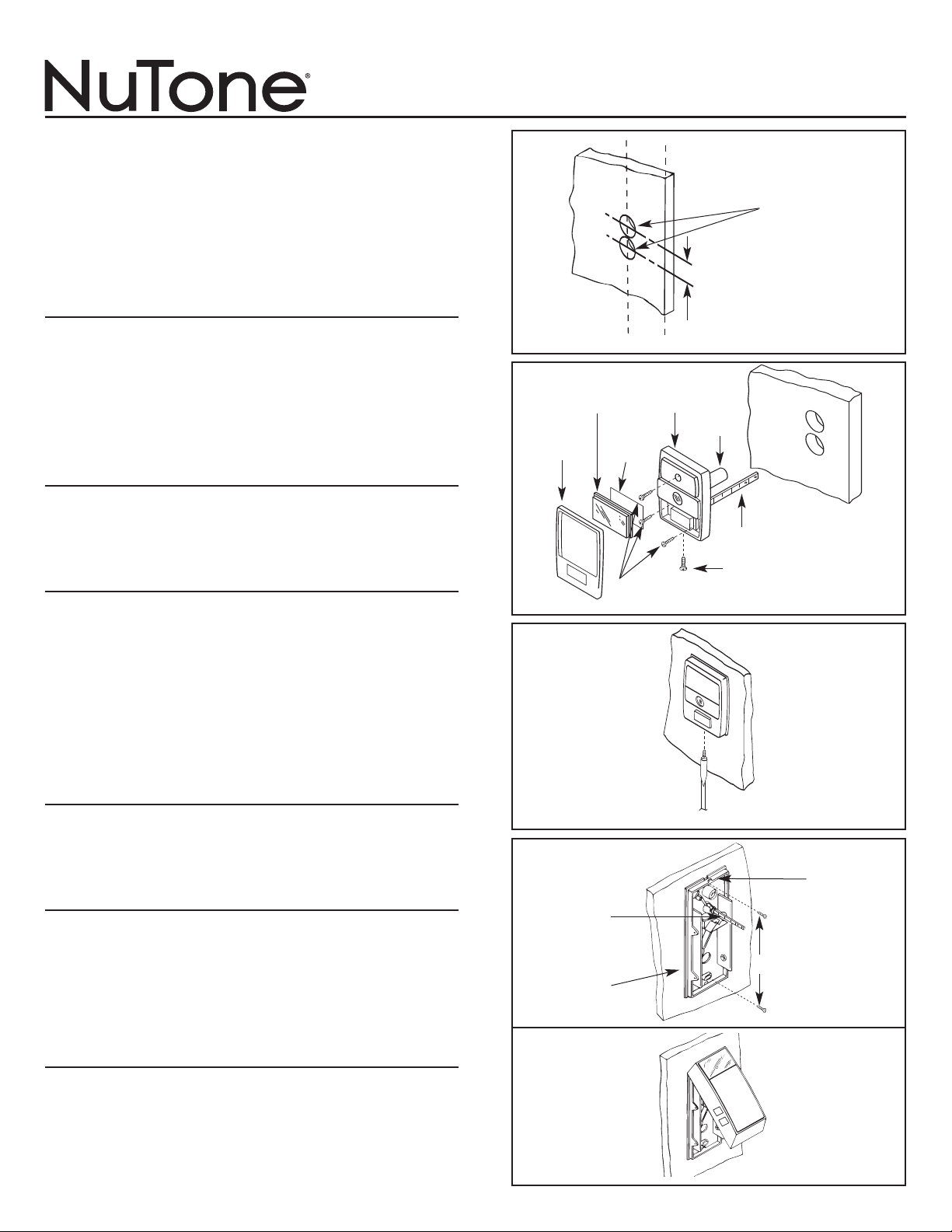
1. The chime should be mounted in the center of the door -
approximately 4
1
⁄2 feet to 5 feet above the floor. NOTE: Be
sure there are no obstructions on the inside of the door to
interfere with the chime’s baseplate.
2. Refer to Figure 1. Mark the location of the mounting holes
parallel to the edge of the door. NOTE: It is important that
the holes are parallel to the edge of the door for proper
operation of the chime.
PUSHBUTTON ASSEMBLY
NOTE: If the pushbutton assembly is located in a position
that is exposed to the rain, it is recommended that a bead of
caulking material is placed around the 1" holes before the
pushbutton assembly is installed.
NAME CARD HOLDER
1. Refer to Figure 2. Print or type name and address on card
(supplied). Place the card in holder with printing toward the
front and secure in place with metal trim.
2. Remove metal trim, name card holder, and name card
from the pushbutton housing to reveal mounting holes.
3. Locate viewer and pushbutton shaft into predrilled holes
until the mechanism is flush against the door and in place
with mounting screws provided.
4. Refer to Figure 3. Secure metal trim in place by tightening
the screw located at the bottom of the unit.
MOUNTING THE BASEPLATE
1. Refer to Figure 4. Position the baseplate mechanism over
the pushbutton shaft and viewer. Align baseplate parallel
with the edge of the door and insert the top and bottom
mounting screws provided. Tighten screws securely.
OPERATION
1. Check the door chime by pressing the pushbutton. The
chime should sound two (2) notes.
2. If the door chime does not operate properly, check the
baseplate mechanism and pushbutton assembly. Both
assemblies must be parallel to the door for proper chime
operation.
3. If necessary, re-position the assembly.
MOUNTING THE CHIME COVER
Refer to Figures 4 and 5.
1. Break off the surplus pushbutton shaft to insure proper
clearance when the cover is in place.
2. Place the tab located on top of the baseplate into the slot
located in the top of the cover.
3. Position the cover over the tab and push cover flush with
the door.
TO REGISTER THIS PRODUCT, VISIT WWW.NUTONE.COM
INSTALLATION INSTRUCTIONS
READ & SA
VE THESE INSTRUCTIONS!
Two-Note Non-Electric
Door Chime - with Viewer
FIGURE 1
FIGURE 2
JOS. NEIL
FIGURE 3
DRILL TWO
1” HOLES
PARALLEL
TO EDGE
OF DOOR
DISTANCE
BETWEEN
CENTERS
1
1
⁄16”
METAL TRIM
HOLD DOWN
SCREW
PUSHBUTTON
SHAFT
MOUNTING
SCREWS
PUSHBUTTON
MECHANISM
NAME CARD
HOLDER
NAME
CARD
METAL
TRIM
VIEWER
FIGURE 4
FIGURE 5
BREAK OFF
SURPLUS
PUSHBUTTON
SHAFT
EDGE OF
MECHANISM
MUST BE
PARALLEL TO
EDGE OF DOOR
COVER
MOUNTING
TABS
MOUNTING SCREWS

• El carillón no eléctrico se monta directamente a través de la
puerta y funcionará con puertas del grueso de 1,9 cm a 5 cm (
3
⁄4
de pulgada hasta 2 pulgadas)
• El carillón incluye un mirador
COLOCANDO EL CARILLÓN DE PUERTA
1. El carillón debe estar montado en el centro de la puerta -
apoximamente 1,4 a 1,5 metros (4.5 a 5 pies) encima del suelo.
NOTA: Asegure que no hayan obstáculos en la parte interior
de la puerta que puedan interferir con la placa de la base del
carillón.
2. Vea la Figura 1. Marque el lugar de los hoyos de montura en
paralelo al borde de la puerta para la operación correcta del
carillón.
ENSAMBLE DEL BOTÓN
NOTA: Si el ensamble del botón está en un lugar dispuesto ala
lluvia, se recomienda poner una línea de enmasillado alrededor de
los hoyos de 2,5 cm antes de instalar el ensamble del botón.
MONTURA DE LA TARJETA CON NOMBRE
1. Vea la Figura 2. Escriba o imprima nombre y dirección en la
tarjeta (provista). Ponga la montura de la tarjeta con la
impresión hacia adelante y fíjela en su lugar con el marco
metálico.
2. Remueva el marco de metal, la montura de la tarjeta y la tarjeta
de la cubierta del botón para que se vean los hoyos de
montura.
3. Ubique el mirador y el eje del botón en los hoyos perforados
hasta que el mecanismo esté empotrado contra la puerta y en
su lugar con los tornillos de montaje provistos.
4. Vea la Figura 3. Fije el marco metálico en su lugar al apretar el
tornillo ubicado al fondo de la unidad.
MONTAJE DE LA PLACA BASE
1. Vea la Figura 4. Coloque el mecanismo de la placa base sobre
el eje del botón y el mirador. Alínie la placa base en paralelo
con el borde de la puerta e insierte los tornillos de montaje
provistos. Aprete bien los tornillos.
OPERACIÓN
1. Verifique que funciona el carillón tocando el botón. El carillón
debe sonar dos (2) tonos.
2. Si el carillón no funciona bien, verifique el mecanismo de la
placa base y el ensamble de botón. Los dos ensambles deben
estar paralelo con la puerta para operación correcta del carillón.
3. Si es necesario, coloque de nuevo el ensamble.
MONTAJE DE LA CUBIERTA DEL CARILLÓN
Vea las Figuras 4 y 5.
1. Rompa la parte sobrante del eje del botón para asegurar la
separación cuando la cubierta está en su lugar.
2. Coloque la lengüeta localizada de la parte superior de la placa
en la ranura en la parte superior de la tapa.
3. Coloque la cubierta sobre la lengüeta y empuje la tapa hasta
que esté empotrada con la puerta.
PARA COLOCAR ESTE PRODUCTO, VISITE WWW.NUTONE.COM
INSTRUCCIONES DE INSTALACION
¡LEA Y GUARDE ESTAS INSTRUCCIONES!
Carillón no Eléctrico para
Puerta de Dos Tonos - con Mirador
FIGURA 1
FIGURA 2
JOS. NEIL
FIGURA 3
TALADRE DOS
HOYOS DE 2,5 CM
EN PARALELO CON
EL BORDE DE LA
PUERTA
DISTANCIA
ENTRE LOS
CENTROS
3 CM
TORNILLO PARA
FIJAR EL MARCO
METÁLICO
EJE DEL BOTÓN
TORNILLOS
DE MONTAJE
MECANISMO
DEL BOTÓN
MONTURA DE LA
TARJETA DEL
NOMBRE
TARJETA
DE
NOMBRE
MARCO
METÁLICO
MIRADOR
FIGURA 4
FIGURA 5
ROMPA
SOBRANTE
DEL EJE DEL
BOTÓN
BORDE DEL
MECANISMO TIENE
QUE ESTAR
PARALELO AL BORDE
DE LA PUERTA
LENGÜETAS
DE LA TAPA
DE MONTURA
TORNILLOS DE MONTAJE

• Ce carillon de porte non-électrique s’installe directement à travers la porte et
peut être installé sur une porte d’une épaisseur variant de 1,905 cm à 5,08 cm.
• Le carillon est muni d’un afficheur.
EMPLACEMENT DU CARILLON DE PORTE
1. Le carillon devrait être installé au centre de la porte, à environ 1,23 m à 1,52 m
du bas de la porte. REMARQUE: Assurez-vous qu’il n’y ait aucune obstruction
à l’intérieur de la porte qui pourrait interférer avec le socle du carillon.
2. Veuillez consulter la figure 1. Marquez l’emplacement des trous d’installation
qui se trouvent en parallèle avec le bord de la porte. REMARQUE: Il est
important que les trous soient en parallèle avec le bord de la porte afin que le
carillon fonctionne correctement.
ASSEMBLAGE DU BOUTON-POUSSOIR
REMARQUE: Si l’assemblage du bouton-poussoir se trouve à un endroit où il
sera exposé à la pluie, il est recommandé qu’une bille de scellant soit ajoutée
autour des trous de 2,54 cm avant d’y installer le bouton-poussoir.
PLAQUETTE D’IDENTIFICATION
1. Veuillez consulter la figure 2. Imprimez ou tapez le nom et l’adresse sur la
carte (fournie). Placez la carte dans la plaquette d’identification, en prenant soin
de placer le côté d’impression vers l’avant, puis fixez en place à l’aide de la
bordure métallique.
2. Retirez la bordure métallique, la plaquette d’identification et la carte nominative
du boîtier du bouton-poussoir afin de révéler les trous d’installation.
3. Placez l’afficheur et la tige du bouton-poussoir dans les trous ayant déjà été
perforés à cet effet, jusqu’à ce que le mécanisme soit égal à la porte et fixé en
place à l’aide des vis d’installation fournies à cet effet.
4. Veuillez consulter la figure 3. Fixez la bordure métallique en place en serrant
les vis se trouvant au bas de l’unité.
INSTALLATION DU SOCLE
1. Veuillez consulter la figure 4. Placez le mécanisme du socle au-dessus de la
tige du bouton-poussoir et de l’afficheur. Alignez le socle en parallèle au bord de
la porte et insérez les vis de fixation du haut et du bas ayant été fournies à cet
effet. Serrez les vis.
FONCTIONNEMENT
1. Essayez le carillon de porte en appuyant sur le bouton-poussoir. Deux tons
devraient se faire entendre.
2. Si le carillon ne fonctionne pas de façon appropriée, vérifiez le mécanisme du
socle et l’assemblage du bouton-poussoir. Les deux assemblages doivent être
en parallèle avec la porte afin que le carillon fonctionne correctement.
3. Au besoin, repositionnez l’assemblage.
INSTALLATION DU CARILLON DE LA PORTE
Veuillez consulter les figures 4 et 5.
1. Veuillez couper le surplus de la tige du bouton-poussoir afin qu’il y ait
suffisamment d’espace une fois le couvercle en place.
2. Placez l’onglet qui se trouve sur le socle dans la fente se trouvant au-dessus du
couvercle.
3. Positionnez le couvercle au-dessus de l’onglet et appuyez sur ce premier
jusqu’à ce qu’il soit égal à la porte.
POUR ENREGISTRER SE PRODUIT, VISITEZ WWW.NUTONE.COM
INSTRUCTIONS D’INSTALLATION
LIRE ET CONSERVER CES INSTRUCTIONS!
Carillon de porte non-électrique à
deux tons – avec afficheur
FIGURE 1
FIGURE 2
JOS. NEIL
FIGURE 3
PERCEZ DEUX
TROUS DE 2,54
CM EN
PARALLÈLE
AVEC LE BORD
DE LA PORTE
DISTANCE
ENTRE LES
CENTRES
2,7 CM
VIS DE FIXATION DE
LA BORDURE
MÉTALLIQUE
TIGE DU BOUTON-
POUSSOIR
VIS
D’INSTALLATION
MÉCANISME
DU BOUTON-
POUSSOIR
PLAQUETTE
D’IDENTIFICATION
CARTE
NOMINATIVE
BORDURE
MÉTALLIQUE
AFFICHEUR
FIGURE 4
FIGURE 5
COUPEZ LE
SURPLUS DE
LA TIGE DU
BOUTON-
POUSSOIR
LE BORD DU
MÉCANISME
DOIT ÊTRE EN
PARALLÈLE
AVEC LE BORD
DE LA PORTE
ONGLETS
D’INSTALLATION
DU COUVERCLE
VIS D’INSTALLATION
99524483C
Product specifications subject to change without notice.
One Year Limited Warranty
WARRANTY OWNER: Broan-NuTone warrants to the original consumer purchaser of its products that such products will be free from defects in materials or workmanship for a period of one (1) year
from the date of original purchase. THERE ARE NO OTHER WARRANTIES, EXPRESS OR IMPLIED, INCLUDING, BUT NOT LIMITED TO, IMPLIED WARRANTIES OF MERCHANTABILITY
OR FITNESS FOR A PARTICULAR PURPOSE.
During this one year period, Broan-NuTone will, at its option, repair or replace, without charge, any product or part which is found to be defective under normal use and service. THIS WARRANTY
DOES NOT EXTEND TO FLUORESCENT LAMP STARTERS OR TUBES, FILTERS, DUCT, ROOF CAPS, WALL CAPS AND OTHER ACCESSORIES FOR DUCTING. This warranty does not cover (a)
normal maintenance and service or (b) any products or parts which have been subject to misuse, negligence, accident, improper maintenance or repair (other than by Broan-NuTone), faulty installation
or installation contrary to recommended installation instructions.
The duration of any implied warranty is limited to the one year period as specied for the express warranty. Some states do not allow limitation on how long an implied warranty lasts, so the above
limitation may not apply to you.
BROAN-NUTONE’S OBLIGATION TO REPAIR OR REPLACE, AT BROAN-NUTONE’S OPTION, SHALL BE THE PURCHASER’S SOLE AND EXCLUSIVE REMEDY UNDER THIS WARRANTY.
BROAN-NUTONE SHALL NOT BE LIABLE FOR INCIDENTAL, CONSEQUENTIAL OR SPECIAL DAMAGES ARISING OUT OF OR IN CONNECTION WITH PRODUCT USE OR PERFOR-
MANCE. Some states do not allow the exclusion or limitation of incidental or consequential damages, so the above limitation or exclusion may not apply to you. This warranty gives you specic legal
rights, and you may also have other rights, which vary from state to state. This warranty supersedes all prior warranties.
WARRANTY SERVICE: To qualify for warranty service, you must (a) notify Broan-NuTone at the address or telephone number below, (b) give the model number and part iden-
tication and (c) describe the nature of any defect in the product or part. At the time of requesting warranty service, you must present evidence of the original purchase date.
Date of Installation
Builder or Installer
Model No. and Product Description
IF YOU NEED ASSISTANCE OR SERVICE - CONTACT:
Broan-NuTone LLC Hartford, Wisconsin www.nutone.com 888-336-3948
Broan-NuTone Canada Mississauga, Ontario www.nutone.ca 877-896-1119 Rev. 08/2007
Garantia Limitada de un Año
GARANTÍA DEL PROPIETARIO: Broan-NuTone garantiza al comprador consumidor original de sus productos, por el período de un (1) año desde la fecha original de compra, que tales productos
están libres de defectos en material y mano de obra. NO HAY OTRAS GRANTÍAS, EXPRESADOS O SOBREENTENDIDAS, INCLUYENDO, PERO NO LIMITADAS A, GRANTÍAS NO EXPRE-
SADAS DE MERCHNTIBILIDAD O ADAPTABLES A UN PROPÓSITO EN PARTICULAR.
Durante este período de un año, Broan-NuTone reparará o reemplazará a su opción y sin costo, cualquier producto o parte que se encuentre defectuoso bajo condiciones normales de uso y servicio.
ESTA GARANTÍA NO CUBRE A LOS ARRANCADORES PARA LÁMPARAS FLUORESCENTES O A LOS TUBOS FLUORESCENTES, FILTROS, DUCTOS, TAPAS DE TECHO, TAPAS DE PARED
Y OTROS ACCESORIOS PARA CANALIZACIÓN. Esta granatía no cubre (a) Mantenimiento y servicios normales (b) Productos o partes sujetos al mal uso, negligencia, accidente, mantenimiento
inadecuado o reparaciones (port otros ajenos a Broan-NuTone), instalación defectusoa o a una instalación contraria a las instrucciones de instalación recomendadas.
La duración de cualquier garantia no expresada está limitada a un periodo de un año según se especica en la garantia expresada. Algunos estados no permiten limitación en cuanto a la duración de
una grantia no expresada, por lo que la limitación arriba indicada puede que no se apliqué a Ud.
LA OBLIGACIÓN DE BROAN-NUTONE DE REPARAR O REEMPLAZAR A SU OPCIÓN, SERÁ EL ÚNICO Y EXCLUSIVO RECURSO QUE TENDRÁ EL COMPRADOR BAJO ESTA GARANTÍA.
BROAN-NUTONE NO SERÁ RESPONSABLE POR DAÑOS INCIDENTALES, CONSECUENTES O ESPECIALES QUE RESULTEN A CONSECUENCIA O SEAN INDEPENDIENTE DEL USO O
DESEMPEÑO DEL PRODUCTO. Algunos estados no permiten la exclusión o limitación de daños incidentals o consecuentes, de modo que la limitación o exclusión arriba indicada pueda que no se
aplique a Ud. Esta garantia le proporciona derechos legales especicos, y Ud.puede tener otros derechos, los cuales varían de estado a estado. Esta garantias reemplaza a todas las garantías anteriores..
SERVICO DE GARANTÍA: Para tener derecho al servicio de garantía, Ud. debe (a) Noticar a Broan-NuTone a la dirección o el número de teléfono abajo, (b) indicar el número
de modelo y la identifación de la party y (c) describir la naturaleza de cualquier defecto en la producto o parte. Al momento de solicitor el servicio por la garantía, Ud. debe
presentar la evidencia de la fecha original de compra.
Fecha de la instalación
Constructor o instalador
Número de modelo y descripción del producto
SI NECESITA ASISTENCIA O SERIVIVIO - CONTACTO:
Broan-NuTone LLC Hartford, Wisconsin www.nutone.com 888-336-3948
Broan-NuTone Canada Mississauga, Ontario www.nutone.ca 877-896-1119 Rev. 08/2007
Garantie limitée d’un an
GARANTIE DU PROPRIÉTAIRE: Broan-NuTone garantie à l’acheteur original de ses produits que ces derniers seront exmpts de tout défaut de matériaux et de fabrication pour une période d’un (1)
an à compter de la date d’acha. AUCUNE AUTRE GARANTIE, IMPLICITE OU EXPRESSE, N’EST DONNÉE, Y COMPRIS, MAIS SANS S’Y LIMITER, GARANTIE DE MARCHANDIBILITÉ
OU D’ADAPTATION À UN USAGE PARTICULIER.
Pendant cette période d’un an, Broan-NuTone procédera au remplacement ou à la réparation sans aucuns frais, mais à sa propre discrétion, de tout produit ou pièce jugé défectueux dans le cadre
d’une utilisation normale. CETTE GARANATIE NE VISE PAS LES DISPOSITIFS D’AMORCAGE NI LES TUBES DES LUMINAIRES FLUORESCENTS. Cette garantie ne couvre pas (a) l’entretien et
le service courants ni (b) les produits et les pièces ayant fait l’objet du’n usage abusif, de négligence, d’un accident, d’un entretien ou d’une réparation non appropriée (par du personnel non autorisé
par Broan-NuTone) d’une mauvaise installation ou d’une installation non conforme aux directives d’installation fournies.
La durée de toute garantie implicite est limitée à la période de deux ans précisée pour la garantie expresse. Certains états ne reconnaissent pas les restrictions relatives à la durée des garanties
implicites; il se pourrait donc que cette restriction ne s’applique pas dans votre cas.
LE REMPLACEMENT OU LA RÉPARATION PAR BROAN-NUTONE, À SA PROPRE DISCRÉTION, DE TOUT PRODUIT OU PIÈCE DÉFECTUEUX CONSTITUE LE SEUL REMÈDE DE
L’ACHETEUR EN VERTU DE CETTE GARANTIE. BROAN-NUTONE NE PEUT ÊTRE TENUE RESPONSABLE DES DOMMAGES INDIRECTS, CONSÉCUTIFS OU SPÉCIAUX ATTRIBUABLES
À UTILISATION OU AU RENDEMENT DU PRODUIT. Certains états ne reconnaissent pas les restrictions ni les exclusions relatives aux dommages indirects, consécutifs ou spéciaux; il se pourrait
donc que cette restriction ne s’applique pas dans votre cas. La présente garantie vous accorde des droits spéciques, mais vous pourriez aussi avoir d’autres droits en fonction de l’état dans lequel
vous résidez. Cette garantie remplace toute autre garantie donnée précédement.
SERVICE SOUS GRANTIE: Pour être admissible au service sous garantie, vous devez (a) aviser Broan-NuTone, à l’adresse ou au numéro de téléphone ci-dessous, (b) fournir le
numéro du modèle et la description de la pièce et (c) décrire la nature défaut de la pièce ou du produit. Au moment de la demande de service sous garantie, vous devez fournir
une preuve de la date d’achat originale.
Date d’installation
Entrepeneur ou installateur
N° de modèle et description du produit
POUR OBTENIR DE L’ASSITANCE OU DU SERVICE - CONTACTEZ:
Broan-NuTone LLC Hartford, Wisconsin www.nutone.com 888-336-3948
Broan-NuTone Canada Mississauga, Ontario www.nutone.ca 877-896-1119 Rev. 08/2007
