Register
your product
www.kaercher.com/welcome
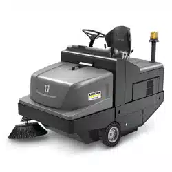
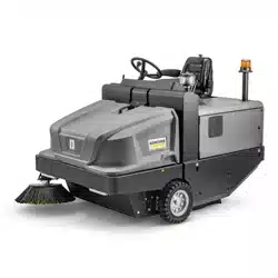
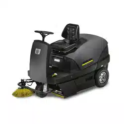
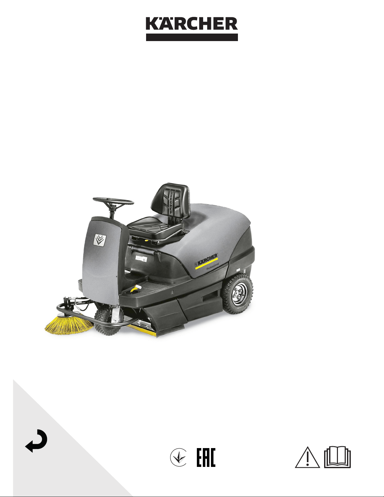
KM 100/100 R G
KM 100/100 R LPG
001
59990940 02/22
-
1
Please read and comply with
these original instructions prior
to the initial operation of your appliance and
store them for later use or subsequent own-
ers.
Please read the safety instructions before
start-up!
Your sales outlet should be informed about
any transit damage noted when unpacking
the product.
– Warning and information plates on the
machine provide important directions
for safe operation.
– In addition to the information contained
in the operating instructions, all statuto-
ry safety and accident prevention regu-
lations must be observed.
Appliance motorisation
G: Petrol engine
LPG: Gas engine
Notes about the ingredients (REACH)
You will find current information about the
ingredients at:
www.kaercher.com/REACH
The warranty terms published by the rele-
vant sales company are applicable in each
country. We will repair potential failures of
your appliance within the warranty period
free of charge, provided that such failure is
caused by faulty material or defects in man-
ufacturing. In the event of a warranty claim
please contact your dealer or the nearest
authorized Customer Service center.
Please submit the proof of purchase.
�
DANGER
To avoid risks, all repairs and replacement
of spare parts may only be carried out by
authorized customer service personnel.
– Only use accessories and spare parts
which have been approved by the man-
ufacturer. The exclusive use of original
accessories and original spare parts
ensures that the appliance can be oper-
ated safely and trouble free.
– For additional information about spare
parts, please go to the Service section
at www.kaercher.com.
Contents
Contents . . . . . . . . . . . . . . . . . EN 1
General notes. . . . . . . . . . . . . EN 1
Combustion engine version EN 1
Environmental protection EN 1
Warranty . . . . . . . . . . . . EN 1
Accessories and Spare
Parts . . . . . . . . . . . . . . . EN 1
Symbols in the operating in-
structions . . . . . . . . . . . EN 2
Symbols on the machine EN 2
Proper use . . . . . . . . . . . . . . . EN 2
Foreseeable misuse . . . EN 2
Suitable surfaces . . . . . EN 2
Safety instructions . . . . . . . . . EN 2
Safety instructions concern-
ing the operation . . . . . . EN 2
Safety information concern-
ing the driving operation EN 2
Safety information concern-
ing the combustion engine EN 2
Safety guidelines for LPG
vehicles (only gas engine) EN 3
Safety information concern-
ing the transport of the appli-
ance . . . . . . . . . . . . . . . EN 4
Safety information concern-
ing maintenance and care EN 4
Function . . . . . . . . . . . . . . . . . EN 4
Operating and Functional Ele-
ments . . . . . . . . . . . . . . . . . . . EN 5
Operator console . . . . . EN 5
Colour coding . . . . . . . . EN 5
Open/ close device hood EN 5
Before Startup . . . . . . . . . . . . EN 6
Unloading . . . . . . . . . . . EN 6
Moving sweeper without en-
gaging self-propulsion. . EN 6
Moving sweeper by engag-
ing self-propulsion. . . . . EN 6
Start up. . . . . . . . . . . . . . . . . . EN 6
General notes . . . . . . . . EN 6
Connect/ change gas cylin-
der (only KM 100/100 R
LPG) . . . . . . . . . . . . . . . EN 6
Refuelling . . . . . . . . . . . EN 6
Operation . . . . . . . . . . . . . . . . EN 7
Adjusting driver's seat. . EN 7
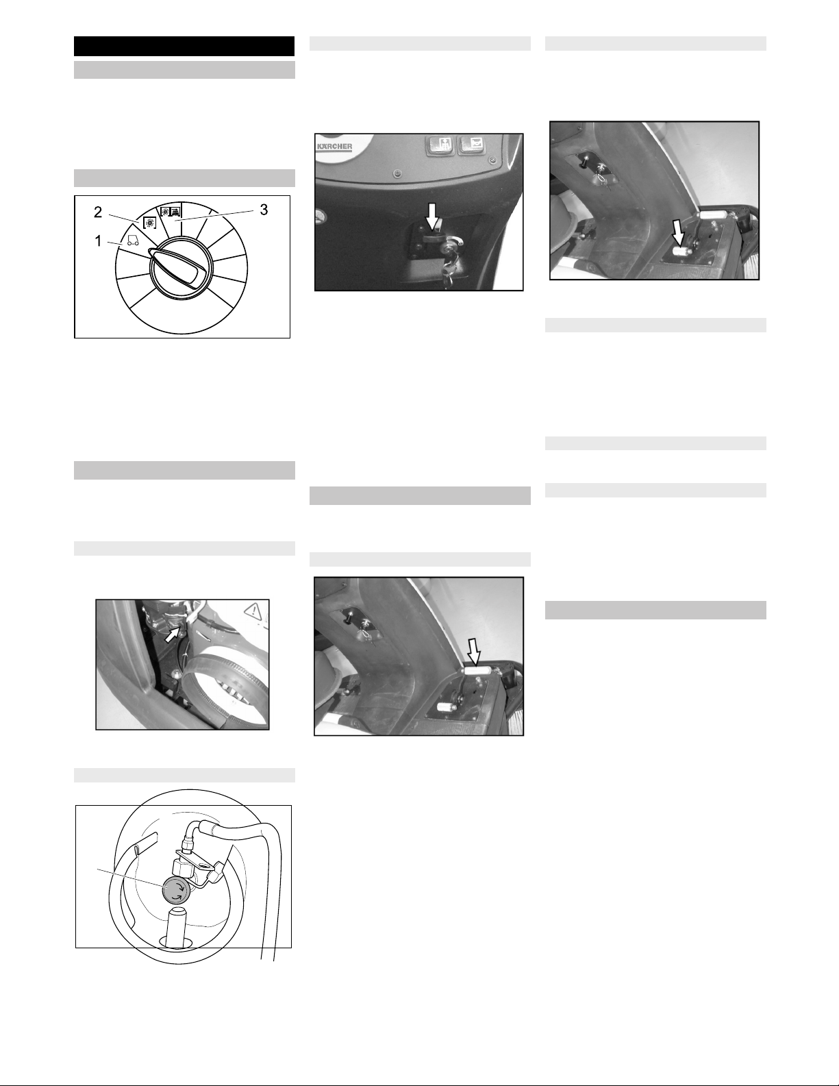
Programme selection . . EN 7
Starting the machine. . . EN 7
Drive the machine. . . . . EN 7
Sweeping mode . . . . . . EN 7
Emptying waste container EN 8
Turn off the appliance . . EN 8
Transport . . . . . . . . . . . EN 8
Storage . . . . . . . . . . . . . EN 8
Shutdown . . . . . . . . . . . . . . . . EN 8
Care and maintenance . . . . . . EN 9
General notes . . . . . . . . EN 9
Cleaning . . . . . . . . . . . . EN 9
Maintenance intervals. . EN 9
Maintenance Works . . . EN 9
Troubleshooting . . . . . . . . . . . EN 13
Technical specifications . . . . . EN 14
EU Declaration of Conformity. EN 15
Declaration of Conformity. . . . EN 15
Accessories . . . . . . . . . . . . . . EN 15
General notes
Combustion engine version
Environmental protection
The packaging material can be
recycled. Please do not throw the
packaging material into house-
hold waste; please send it for re-
cycling.
Old appliances contain valuable
materials that can be recycled.
Please arrange for the proper re-
cycling of old appliances. Please
dispose your old appliances us-
ing appropriate collection sys-
tems.
Engine oil, diesel and petrol must not be
released into the environment. Protect the
ground and dispose of used oil in an envi-
ronmentally responsible way.
Warranty
Accessories and Spare Parts
19EN
-
2
� DANGER
Warns about immediate danger which can
lead to severe injuries or death.
�
WARNING
Warns about possible danger which could
lead to severe injuries or death.
CAUTION
Points out a possibly dangerous situation
which can lead to light injuries or property
damage.
The sweeper is intended for cleaning floor
surfaces for commercial use and e.g. for
the following fields of application:
Car parks
Production facilities
Logistics areas
Hotel
Retail industry
Storage areas
Walkways
– Use this sweeper only as directed in
these operating instructions.
– Any use extending beyond this is not
considered as proper use. The manu-
facturer is not liable for any losses re-
sulting from this; the user alone bears
the risk for this.
– Petrol / diesel engine
: The operation indoors is prohibited.
– Gas engine
: Operating the appliance indoors is
permitted if sufficient ventilation is en-
sured.
Gas bottles and appliance may only be
stored on ground level.
– The machine may not be modified.
– The machine is only suitable for use on
the types of surfaces specified in the
operating instructions.
– The machine may only be operated on
the surfaces approved by the company
or its authorised representatives.
– The following applies in general: Keep
highly-flammable substances away
from the appliance (danger of explo-
sion/fire).
– Never vacuum up explosive liquids,
combustible gases or undiluted acids
and solvents. This includes petrol, paint
thinner or heating oil which can gener-
ate explosive fumes or mixtures upon
contact with the suction air. Acetone,
undiluted acids and solvents must also
be avoided as they can harm the mate-
rials on the machine.
– Never sweep/vacuum up reactive metal
dusts (e.g. aluminium, magnesium,
zinc), as they form explosive gases
when they come in contact with highly
alkaline or acidic detergents.
– Do not sweep/vacuum up any burning
or glowing objects.
– The appliance is not suitable for sweep-
ing off hazardous substances.
– The machine may not be used or stored
in hazardous areas. It is not allowed to
use the appliance in hazardous loca-
tions.
– It is strictly prohibited to take co-pas-
sengers.
– Pushing/pulling or transporting objects
by means of this appliance is prohibit-
ed.
Asphalt
Industrial floor
Screed
Concrete
Paving stones
� Danger
Risk of injury!
Do not use the appliance without an over-
head guard in areas where the operator
might get hit by falling objects.
– The machine with working equipment
must be checked to ensure that it is in
proper working order and is operating
safely prior to use. Otherwise, the appli-
ance must not be used.
– If the appliance is used in hazardous ar-
eas (e.g. filling stations) the corre-
sponding safety provisions must be ob-
served. It is not allowed to use the ap-
pliance in hazardous locations.
– The operator must use the appliance
properly. The person must consider the
local conditions and must pay attention
to third parties, in particular children,
when working with the appliance.
– Prior to starting work, the operator must
ensure that all protective devices are
properly installed and function correct-
ly.
– The operator of the appliance is liable
for accidents with other individuals or
their property.
– Ensure that the operator wears tight-fit-
ting clothes. Wear sturdy shoes and
avoid wearing loose-fitting clothes.
– Check the immediate vicinity prior to
starting (e.g. children). Ensure suffi-
cient visibility!
– Never leave the machine unattended
so long as the engine is running. The
operator may not leave the machine be-
fore the engine has come to a standstill,
the machine has been protected
against accidental movement and the
parking brake has been applied.
– Please remove the key, when not in
use, to avoid unauthorised use of the
appliance.
– The appliance may only be used by per-
sons who have been instructed in han-
dling the appliance or have proven
qualification and expertise in operating
the appliance or have been explicitly
assigned the task of handling the appli-
ance.
– This appliance is not intended for use
by persons (including children) with lim-
ited physical, sensoric or mental capac-
ities or lack of experience and/or skills,
unless such persons are accompanied
and supervised by a person in charge of
their safety or if they received precise
instructions on the use of this appli-
ance.
– Children should be supervised to pre-
vent them from playing with the appli-
ance.
� Danger
Risk of injury!
Danger of tipping if gradient is too high.
– The falling and rising gradients in the di-
rection of travel may not exceed 18%.
Danger of tipping on unstable ground.
– Only use the machine on sound surfac-
es.
Danger of tipping with excessive sideways
tilt.
– The gradient perpendicular to the direc-
tion of travel should not exceed 15%.
The travel speed must be adapted to the
existing conditions.
� Danger
Risk of injury!
– Please observe the special safety infor-
mation in the operating instructions of
the engine manufacturer.
– Do not close the exhaust.
– Do not bend over the exhaust or touch
it (risk of burns).
– Do not touch the drive motor (risk of
burns).
– Petrol / diesel engine: It is prohibited to
operate the appliance indoors (risk of
poisoning).
– Gas engine: When operating the appli-
ance indoors, ensure sufficient ventila-
tion and discharge of the exhaust gases
(risk of poisoning).
– Exhaust gases are poisonous and haz-
ardous to health, do not inhale them.
Symbols in the operating
instructions
Symbols on the machine
Please do not sweep away
any burning substances
such as cigarettes, match
sticks or similar objects.
Risk of being squeezed or
hurt at the belts, side-
brushes, containers, ma-
chine cover.
Proper use
Foreseeable misuse
Suitable surfaces
Safety instructions
Safety instructions concerning the
operation
Safety information concerning the
driving operation
Safety information concerning the
combustion engine
20 EN

-
3
– The engine requires approx. 3-4 sec-
onds to come to a standstill once it has
been switched off. During this time, stay
well clear of the working area.
Hauptverband der gewerblichen Beruf-
sgenossenschaften e.V. (HVBG / Germa-
ny). Liquefied gases (propellants) are bu-
tane and propane or a mixture of butane/
propane. They are available in special cyl-
inders. The operating pressure of these
gases depends on the outside tempera-
ture.
� Danger
Risk of explosion! Do not handle liquified
gas like petrol. Petrol evaporates slowly,
liquified gas immediately turns into gas.
The risk of gas spreading in the room and
getting ignited is thus higher in case of liq-
uefied gas than in petrol.
� Danger
Risk of injury! Use only liquefied gas cylin-
ders with propellant filled according to DIN
51622 of A or B quality, depending on the
surrounding temperature.
CAUTION
Use of cooking gas is strictly prohibited. For
the gas engine, use only liquid gas mix-
tures of propane/ butane or their mixtures
where the mixing ratio lies between 90/10
to 30/70. On account of better cold start be-
haviour even at low outside sub-zero tem-
peratures (below 0° C / 32 °F) always pre-
fer a mixture with a higher propane share
because evaporation takes place even at
low temperatures.
– All persons handling liquid gases are li-
able to acquaint themselves with the
special properties of the liquefied gases
for hazard-free handling of operations.
The current documentation is always to
be kept with the sweeper.
– Propellant-operated units are to be
checked at regular intervals, at least
once a year, by an expert against leaks
(according to BGG 936) and ensure
that the unit is functioning properly.
– The inspection must be certified and
documented. The inspection guidelines
are § 33 and § 37 UVV (occupation ac-
cident prevention regulations) "Use of
liquid gas" (BGV D34).
– General applicable regulations are the
guidelines for inspecting vehicles
whose engines are driven by liquefied
gases of the Federal Transportation
Minister.
– Gas must always be drawn only from
one cylinder. Drawing gas from multiple
cylinders simultaneously can cause liq-
uid gas from one cylinder flowing into
the other. This causes the over-filled
cylinder to be subjected to an unpermit-
ted excess pressure when the cylinder
valve is closed later (refer B.1 of these
guidelines).
– Ensure the correct positioning of the
cylinder with the "top" marking while
connecting a full cylinder (the connec-
tion screw points vertically upward).
Perform the replacement of the gas cylin-
der carefully. During assembly and disas-
sembly, the gas outlet nozzle of the cylin-
der valve must be sealed by means of a
cap nut that is tightened using a wrench.
– Discontinue the use of leaky gas cylin-
ders. Such cylinders are to be emptied
by slowly letting out the gas in open
spaces by conforming to all safety reg-
ulations and are to be indicated as
leaky. Also inform the issuing company
or its representative (the filling-station
attendant) in writing about the damage
to the cylinder while delivering or re-
ceiving the cylinders.
– Before connecting the gas cylinder,
check that its connection neck is in a
proper state.
– After connecting the cylinder, regularly
check that it is not leaky by using a
foaming agent.
– Open the valves slowly. Do not use
hammers to open and close the cylin-
ders.
– Use only dry fire extinguishers (with
carbonic acid gas) in case of fire
caused by liquefied gases.
– The entire LPG unit must be continu-
ously checked to ensure that there are
no leaks and the unit is functioning
properly. Using the vehicle with a leaky
gas unit is strictly prohibited.
– First close the cylinder valve before
loosening the pipe or tube connection.
Unscrew and loosen the connection nut
of the gas cylinder slowly because oth-
erwise the gas under pressure in the
tube will flow out instantly.
– If the gas is refilled from a larger tank,
then ask the sales agent of the LPG
about the important regulations to be
followed.
� Danger
Risk of injury!
– LPG in a liquid state can cause frost
bites on bare skin.
– After disconnecting the cylinder, tighten
the closing nut firmly on the connecting
threading of the cylinder.
– Use soap water or some such foaming
agent to check whether the cylinder is
leaking. The use of open flames to illu-
minate the LPG unit is strictly prohibit-
ed.
– Follow the manufacturer's installation
specifications while changing individual
parts of the LPG unit. Close all cylinder
and locking valves while doing so.
– Regularly check the status of the elec-
trical unit of the LPG vehicles. Sparks
can cause explosions if the gas-carry-
ing parts of the unit are leaky.
– If a LPG-driven vehicle has been idling
for a long time, then first ventilate the
setting room before commissioning the
vehicle or its electrical unit.
– Immediately inform the trade associa-
tion and the concerned trade superviso-
ry authority about accidents with gas
cylinders or LPG units. Store the dam-
aged parts carefully until all investiga-
tions have been completed.
– Propellants or LPG cylinders must al-
ways be stored according to the regula-
tions of TRF 1996 (Technical Regula-
tions for Liquid Gases, refer DA to BGV
D34, Appendix 4).
– Always store the gas cylinders in a ver-
tical position. Use of open flames and
smoking at the installation site of the
cylinders and during repairs is strictly
prohibited. Protect the stored cylinders
against unauthorised access. Close all
empty cylinders properly.
– Close the cylinder and main locking
valves immediately when you switch off
the vehicle.
– Follow the regulations for garages and
the construction guidelines of the re-
spective State about the location and
structure of the parking areas for LPG-
driven vehicles.
– Gas cylinders are to be stored in sepa-
rate rooms away from the parking areas
(refer DA to BGV D34, Appendix 2).
– The electrical hand-held lamps used in
the rooms are to be equipped with
closed, sealed case and a strong pro-
tection cover.
– Close all cylinder and main valves be-
fore working in repair workshops and
protect the gas cylinders against effect
of external heat.
– A responsible person must check that
all valves, especially the cylinder
valves, are closed during operational
breaks and before closing the factory.
Do not carry out any jobs involving fire -
such as cutting and welding jobs - in the
vicinity of the gas cylinders. Do not
store gas cylinders, not even empty
ones, in the workshops.
– The parking and storage rooms and the
repair workshops must be ventilated
properly. Please note that liquefied gas-
es are heavier than atmospheric air.
They get collected on the floor, in re-
cesses and other holes in the floors and
form a gas-air mixture that can lead to
explosions.
Safety guidelines for LPG vehicles
(only gas engine)
Liabilities of the factory management
and the employee
Maintenance by expert
Commissioning/Operations
In the installation and storage rooms as
well as the workshops
21EN

-
4
– The engine is to be brought to a stand-
still and the appliance is to be fastened
properly during transportation.
Close fuel cock.
– First switch off the appliance and re-
move the ignition key before performing
any cleaning or maintenance tasks on
the appliance, replacing parts or switch-
ing over to another function.
– Always disconnect the battery when
working on the electrics.
– Do not clean the appliance with a water
hose or high-pressure water jet (danger
of short circuits or other damage).
– Maintenance work may only be carried
out by approved customer service out-
lets or experts in this field who are famil-
iar with the respective safety regula-
tions.
– Please observe the local safety regula-
tions regarding portable commercially
used appliances.
– Always use appropriate gloves while
working on the device.
The sweeper operates using the overthrow
principle.
– The side brushes (3) clean the corners
and edges of the surface, moving dirt
and debris into the path of the roller
brush.
– The rotating roller brush (4) moves the
dirt and debris directly into the waste
container (5).
– The dust raised in the container is sep-
arated by the dust filter (2) and the fil-
tered clean air is drawn off by the suc-
tion fan (1).
Safety information concerning the
transport of the appliance
Safety information concerning
maintenance and care
Function
22 EN
-
5
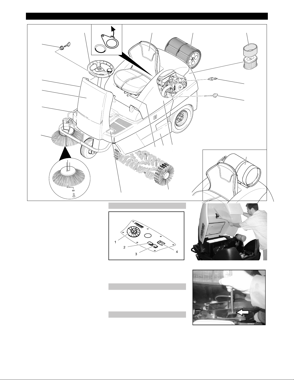
1 Dust filter
2 Air filter insert
3 Spark plug
4 Oil dipstick
5 Gas cylinder (only KM 100/100 R LPG)
6 Cover
7 Waste container (both sides)
8 Lever for seat adjustment
9 Roller brush
10 Pedal for raising/lowering bulk waste
flap
11 Side brushes
12 Drive pedal
13 Front panel
14 Choke (cold start)
15 Ignition lock
16 Steering wheel
17 Wet/dry flap
18 Seat (with seat contact switch)
1 Programme switch
2 Filter dedusting
3 Horn
4 Operating hour counter
– The operating elements for the cleaning
process are yellow.
– The controls for the maintenance and
service are light gray.
� DANGER
Danger of crushing while closing the ma-
chine cover. Hence, lower the machine
cover slowly.
Open the device hood at the handle slot
(pull it upward).
Pull the holding bar from the holder.
Insert the holder bar into the intake on
the suction fan.
To close the appliance hood, pull the
holder bar out of the intake and lock the
holder into the appliance hood.
Operating and Functional Elements
1 2
3
4
5
9
10
12
13
14
15
17 1816
6
8
7
11
Operator console
Colour coding
Open/ close device hood
23EN
-
6
�
DANGER
Risk of injury and damage! Do not use a
forklift to unload the appliance.
To unload the machine, proceed as follows:
Cut plastic packing belt and remove foil.
Remove the elastic tape fasteners at
the stop points.
Four indicated floor boards of the pallet
are fastened with screws. Unscrew
these boards.
Place the boards on the edge of the pal-
let. Place the boards in such a way that
they lie in front of the four wheels of the
machine. Fasten the boards with
screws.
Slide the four support beams included
in the packaging under the ramp.
Remove the wooden blocks used for ar-
resting the wheels and slide them under
the ramp.
� Danger
Risk of injury! Before engaging the free-
wheel operation, the machine must be se-
cured to prevent it rolling away.
NOTICE
Do not move the machine for long distanc-
es without engaging self-propulsion, a
speed of 6 km/h should not be exceeded.
1 Position of the freewheel lever up - ap-
pliance can be pushed.
Opening and securing cover
Engage the freewheel lever in the upper
position.
This blocks the travel drive function.
Close cover.
The machine can now be pushed.
1 Position freewheel lever down - appli-
ance is ready to start.
Engage the freewheel lever in the lower
position.
Close cover.
The appliance can now be driven.
Park the sweeper on an even surface.
Remove the key.
� WARNING
Only type-tested replacement bottles (pow-
er gas bottles) with 11 kg of content must
be used. These have a 270° collar for the
protection of the valve.
�
Danger
Risk of injury!
– Follow safety regulations for LPG vehi-
cles.
– Formation of crusts and yellow-frothing
deposits on the gas cylinder indicate
leakiness.
– Cylinders must be changed only by in-
structed persons.
– Cylinders containing propellant gases
must not be changed in garages and
underground areas.
– Do not smoke and use uncovered light
while changing the cylinder.
– While changing cylinders, first close the
locking valve of the LPG cylinder firmly
and immediately put the protective cap
on the empty cylinder.
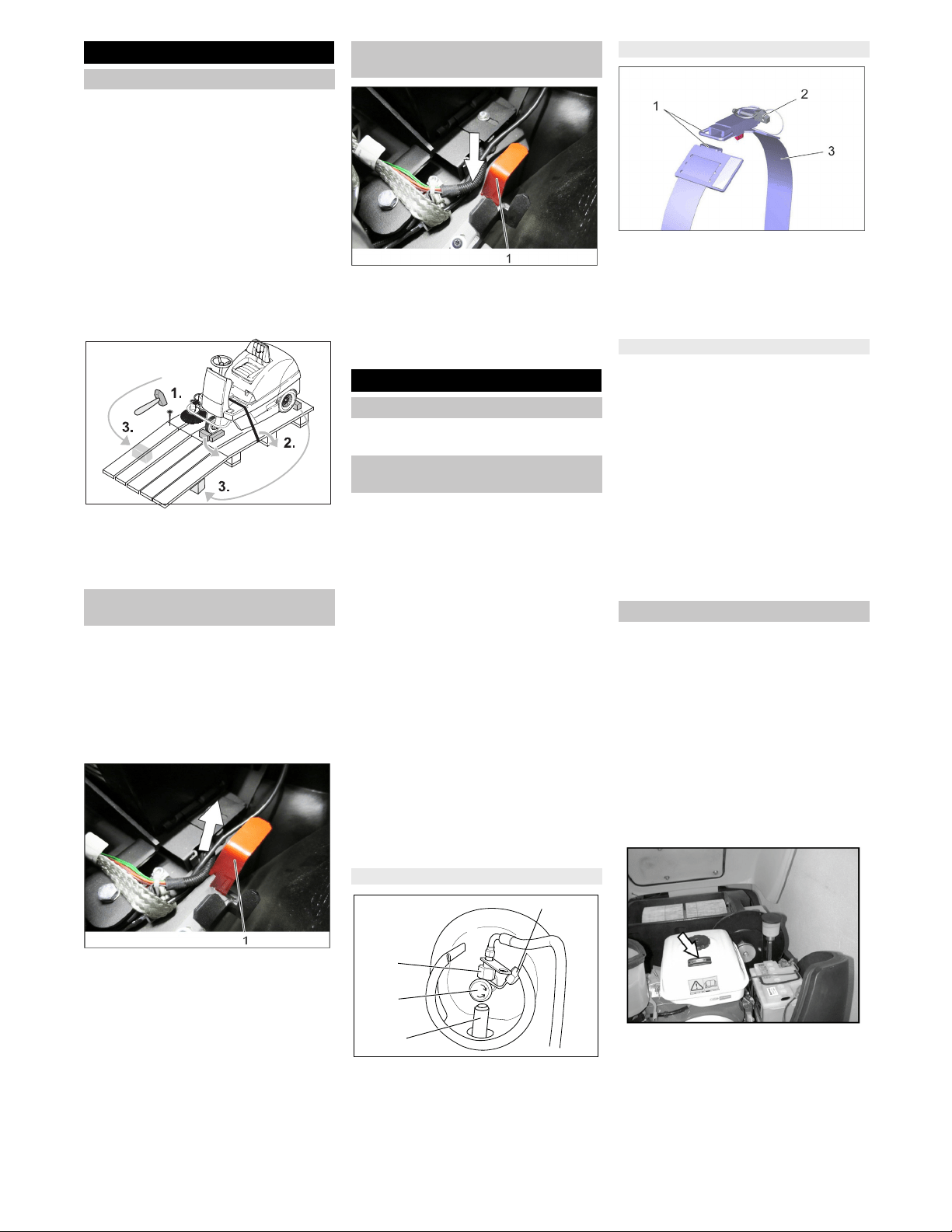
1 Protective cover
2 Union joint
3 Gas withdrawal valve
4 Fixing
Insert the gas cylinder in the fixing; the
gas cylinder connection must point up-
wards.
Illustration: shown without gas cylinder
1 Lock
2 Safety splint
3 Fastening belt
Close the lock on the fastening belt.
Attach safety splint.
NOTICE
Connection has a left threading.
�
WARNING
Do not open the gas drawing valve until be-
fore starting the device (refer to chapter
"Operation | Driving").
�
WARNING
Danger through escaping gas. Route/at-
tach the gas hose so that it does not pro-
trude outside the appliance and cannot be
torn off during operation.
Remove the protective cap from the
connecting valve of the gas cylinder.
Connect the gas tube with Union nut
(use 30 mm spanner).
KM 100/100 R G only
� Danger
Risk of explosion!
– Only use the fuels specified in the Op-
erations Manual.
– Do not refuel the machine in enclosed
spaces.
– Smoking and naked flames are strictly
prohibited.
– Ensure that no fuel reaches the hot
open surfaces.
Switch off engine.
Opening and securing cover
Check fuel level via the tank indicator.
Open fuel filler cap.
Use "regular unleaded petrol".
Fill tank to max. 1 cm below the lower
edge of the filler nozzle.
Wipe off any spilt fuel, remove funnel
and close fuel filler cap.
Close cover.
Before Startup
Unloading
Moving sweeper without engaging
self-propulsion
Moving sweeper by engaging self-
propulsion
Start up
General notes
Connect/ change gas cylinder (only
KM 100/100 R LPG)
Attach gas cylinder
1
2
3
4
Fasten gas cylinder
Connect gas cylinder
Refuelling
24 EN
-
7
Pull seat adjustment lever inwards.
Slide seat, release lever and lock in
place.
Check that the seat is properly locked in
position by attempting to move it back-
wards and forwards.
1 Driving
Driving to the Place of Use.
2 Sweeping with sweep roller
Roller brush is lowered. The roller brush
and the side brush will rotate.
3 Sweeping with side brushes
Roller brush and side brushes are low-
ered.
NOTICE
The machine is equipped with a seat con-
tact mat. If the driver's seat is vacated, the
machine is switched off.
KM 100/100 R G only
Opening and securing cover
Push lever in "ON" direction.
Close cover.
KM 100/100 R LPG only
1 Gas withdrawal valve
Open the gas drawing valve by turning
it in anti-clockwise direction.
Sit on the driver's seat.
Do NOT press the accelerator pedal.
Set programme switch to step 1 (driv-
ing).
KM 100/100 R G only
Press choke lever downwards. Once
the engine is running, pull choke lever
back up.
KM 100/100 R LPG only
Press the remote button, once the mo-
tor runs, release the remote button
Turn ignition key past position 1.
If the machine starts, release the igni-
tion key.
NOTICE
Never operate the starter motor for longer
than 10 seconds. Wait at least 10 seconds
before operating the starter motor again.
� DANGER
Danger of falling! Do not stand up while
driving.
Press slowly the accelerator pedal "for-
ward".
� Danger
Risk of injury! While reversing, ensure that
there is nobody in the way, ask them to
move if somebody is around.
Press slowly the accelerator pedal "re-
verse".
– The accelerator pedal can be used to
vary the driving speed infinitely.
– Avoid pressing the pedal suddenly as
this may damage the hydraulic system.
– In the event of power loss on inclined
surfaces, slightly reduce the pressure
on the accelerator pedal.
Release the accelerator pedal, the ma-
chine brakes automatically and stops.
Driving over fixed obstacles which are 50
mm high or less:
Drive forwards slowly and carefully.
Driving over fixed obstacles which are
more than 50 mm high:
Only drive over these obstacles using a
suitable ramp.
� Danger
Risk of injury! If the bulk waste flap is open,
stones or gravel may be flung forwards by
the roller brush. Make sure that this does
not endanger persons, animals or objects.
CAUTION
Do not sweep up packing strips, wire or
similar objects as this may damage the
sweeping mechanism.
CAUTION
To avoid damaging the floor, do not contin-
ue to operate the sweeping machine in the
same position.
Note: To achieve an optimum cleaning re-
sult, the driving speed should be adjusted
to take specific situations into account.
Note: During operation, the waste contain-
er should be emptied at regular intervals.
Note: When cleaning surfaces, only lower
the roller brush.
Note: Also lower side brush when cleaning
along edges.
Operation
Adjusting driver's seat
Programme selection
Starting the machine
Open fuel cock
Open the gas supply
1
Starting the machine
Drive the machine
Drive forward
Reverse drive
Driving method
Brakes
Driving over obstacles
Sweeping mode
25EN
-
8
Set programme switch to step 2. Roller
brush is lowered. The roller brush and
the side brush will rotate.
Note: The bulk waste flap must be raised
briefly to sweep up larger items (up to 60
mm high), e.g. soft drink cans.
Raising bulk waste flap:
Press the pedal for the bulk waste flap
forwards and keep pressed down.
To lower it, take foot off pedal.
Note: An optimum cleaning result can only
be achieved if the bulk waste flap has been
lowered completely.
Set programme switch to step 3. Side
brushes and roller brush are lowered.
Note: Roller brush and side brush start op-
erating automatically.
Note: During operation, the waste contain-
er should be emptied at regular intervals.
Note: During operation, the dust filter
should be shaken off and cleaned at regu-
lar intervals.
Close wet/dry flap
Open wet/dry flap.
Note: You can thus prevent the filter sys-
tem from getting blocked.
Open wet/dry flap.
Note: This protects the filter from moisture.
– Switch on manual filter shake off.
Press Filter shake off button. The filter
will be cleaned for 15 seconds.
Note: Wait until the filter shaking process is
finished and the dust has settled before you
open or empty the waste container.
Raise the waste container slightly and
pull it out.
Empty waste container.
Push in the waste container and lock it.
Empty opposite waste container.
Set programme switch to step 1 (driv-
ing). The side brush and roller brush are
raised.
Turn ignition key to "0" and remove it.
Note: Once the machine has been
switched off, the dust filter is shaken auto-
matically for approx. 15 seconds. Do not
open the machine hood during this period.
Note: The machine has been fitted with an
automatic parking brake that is activated as
soon as the engine is switched off and the
driver leaves his seat.
KM 100/100 R G only
Close fuel cock.
KM 100/100 R LPG only
1 Gas withdrawal valve
Close gas drawing valve by turning it in
clock-wise direction.
� DANGER
Risk of injury and damage! Observe the
weight of the appliance when you transport
it.
Turn ignition key to "0" and remove it.
Secure the wheels of the machine with
wheel chocks.
Secure the machine with tensioning
straps or cables.
When transporting in vehicles, secure
the appliance according to the guide-
lines from slipping and tipping over.
Note: Observe markings for fixing points
on base frame (chain symbols). When
loading or unloading the machine, it may
only be operated on gradients of max. 18%.
KM 100/100 R G only
Close fuel cock.
Empty fuel tank.
KM 100/100 R LPG only
Close gas drawing valve by turning it in
clock-wise direction.
Remove the gas bottle and dispose of
according to the applicable rules and
regulations.
� DANGER
Risk of injury and damage! Note the weight
of the appliance in case of storage.
If the sweeper is going to be out of service
for a longer time period, observe the follow-
ing points:
Park the sweeper on an even surface.
Set programme switch to step 1 (driv-
ing). The roller brush and side brushes
are raised to prevent the bristles being
damaged.
Turn ignition key to "0" and remove it.
Lock the sweeper to ensure that it does
not roll off.
Clean the inside and outside of the
sweeper.
Park the machine in a safe and dry
place.
KM 100/100 R G only
Fill fuel tank and close fuel cock.
KM 100/100 R LPG only
Close gas drawing valve by turning it in
clock-wise direction.
Remove the gas bottle and dispose of
according to the applicable rules and
regulations.
All motor models:
Change the engine oil
Unscrew spark plugs and pour approx.
3 cm³ of oil into the spark plug hole.
Crank the engine several times before
replacing the spark plug. Screw in the
spark plug.
Disconnect battery.
Charge battery approx. every 2 months.
Sweeping with sweep roller
Sweeping with bulk waste flap raised
Sweeping with side brushes
Sweeping dry floors
Sweep in fibrous and dry waste (such as
dry grass, hay)
Sweeping damp or wet floors
Filter dedusting
Emptying waste container
Turn off the appliance
Transport
1
Storage
Shutdown
26 EN
-
9
First switch off the appliance, remove
the key and remove the battery plug or
disconnect the battery before perform-
ing any cleaning or maintenance tasks
on the appliance, replacing parts or
switching over to another function.
Pull out the battery plug or clamp the
battery while working on the electrical
unit.
– Maintenance work may only be carried
out by approved customer service out-
lets or experts in this field who are famil-
iar with the respective safety regula-
tions.
– Mobile appliances used for commercial
purposes are subject to safety inspec-
tions according to VDE 0701.
– Use only roller brushes/ side-brushes
that are provided with the appliance or
specified in the Operations Manual.
The use of other roller brushes/ side-
brushes can affect the safety of the ap-
pliance.
CAUTION
Risk of damage! Do not clean the appliance
with a water hose or high-pressure water
jet (danger of short circuits or other dam-
age).
� Danger
Risk of injury! Wear dust mask and protec-
tive goggles.
Open the hood, insert retaining rod.
Clean machine with a cloth.
Blow through machine with com-
pressed air.
Close cover.
Note: The dust filter can be rinsed with wa-
ter. Dry the filter completely before reusing
it.
Clean the machine with a damp cloth
which has been soaked in mild deter-
gent.
Note: Do not use aggressive cleaning
agents.
Note: The elapsed-time counter shows the
timing of the maintenance intervals.
Daily maintenance:
Check the sweeping roller and the side
brush for wear and wrapped belts.
Check tyre pressure.
Check function of all operator control el-
ements.
Weekly maintenance:
Check for smooth running of the
Bowden cables and the moveable parts
Check the sealing strips in the sweep-
ing area for position and wear.
Check dust filter and clean filter box, if
required.
Check the vacuum pressure system.
Maintenance to be carried out every 100
operating hours:
Check function of seat contact switch.
Check tension, wear and function of
drive belts (V-belt and circular belt).
Maintenance following wear:
Replace sealing strips.
Replace roller brush.
Replace side brush.
Note: For description, see section on Main-
tenance work.
Note: Where maintenance is carried out by
the customer, all service and maintenance
work must be undertaken by a qualified
specialist. If required, a specialised Kärch-
er dealer may be contacted at any time.
Maintenance to be carried out after 8 oper-
ating hours:
Carry out initial inspection.
Maintenance to be carried out after 20 op-
erating hours
Maintenance to be carried out every 100
operating hours
Maintenance to be carried out every 300
operating hours
Maintenance to be carried out every 500
operating hours
Maintenance to be carried out every 1000
operating hours
Maintenance to be carried out every 1500
operating hours
Note: In order to safeguard warranty
claims, all service and maintenance work
during the warranty period must be carried
out by the authorised Kärcher Customer
Service in accordance with the mainte-
nance booklet.
Preparation:
Park the sweeper on an even surface.
Turn ignition key to "0" and remove it.
�
DANGER
Risk of injury!
The engine requires 15 seconds to come to
a standstill once it has been switched off.
Do not open the appliance hood during that
period.
�
Danger
Risk of injury! Allow the machine sufficient
time to cool down before carrying out any
maintenance and repair work.
Check gas filter in the screw to gas cyl-
inder to see if it is dirty.
Clean dirty filters with compressed air.
Check gas connections, pipes and
evaporators using leak-search spray for
leaks.
NOTICE
Leaks in the gas cylinder cause formation
of crusts or yellow frothy deposits on the
gas connections, pipes and evaporator.
Contact Kärcher Customer Service for
maintenance of the gas unit.
Park the sweeper on an even surface.
Connect air pressure testing device to
tyre valve.
Check tire pressure (refer to technical
data).
� Danger
Risk of injury!
Park the sweeper on an even surface.
Remove the key.
When carrying out repairs on public
highways, wear warning clothing when
working close to passing traffic.
Check stability of ground. Also secure
the machine with wheel chock(s) to pre-
vent it rolling away.
Check tyres
Check tyre contact face for foreign ob-
jects.
Remove objects found.
Use suitable, commercially available
materials to carry out tyre repairs.
Note: Observe the manufacturer's recom-
mendations. The journey may be resumed
providing that the directions supplied by the
product manufacturer have been observed.
The tyre/wheel change should nonetheless
be carried out as soon as possible.
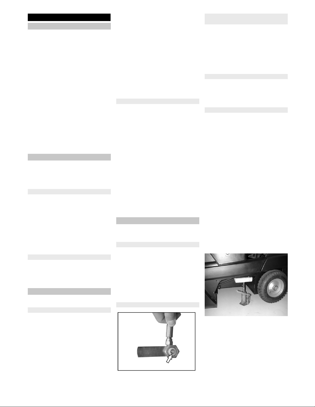
Raise slightly the waste container on
the appropriate side and pull it out.
Loosen the wheel screw.
Install the jack.
Intake point for the jack (rear wheels)
Raise machine using vehicle jack.
Remove the wheel screw.
Remove wheel.
Mount spare wheel.
Screw in the wheel screw.
Lower machine using vehicle jack.
Tighten the wheel screw.
Push in the waste container and lock it.
Note: Use a suitable commercially availa-
ble vehicle jack.
Care and maintenance
General notes
Cleaning
Cleaning the inside of the machine
External cleaning of the appliance
Maintenance intervals
Maintenance by the customer
Maintenance by Customer Service
Maintenance Works
General notes on safety
Check gas filter (only KM 100/100 R LPG)
Check gas connections (only KM 100/
100 R LPG)
Check the tyre pressure
Replacing wheel
27EN
-
10
– The sweeping system is activated by
means of a vacuum pressure system.
– If the side brush or the roller brush can-
not be lowered, the vacuum pressure
sockets must be checked for proper
connection of the hoses, connect the
appropriate hose if necessary.
– If the side brush or the roller brush still
cannot be lowered, the vacuum pres-
sure system has a leak. In this case,
consult Customer Service.
Hose connection at the vacuum pressure
socket of the side brush lowering system
Hose connections at the vacuum pressure
sockets of the roller brush lowering system
Hose connections at vacuum pressure
pump and vacuum pressure socket (accu-
mulator)
Note: The vacuum pressure pump runs
only while the vacuum pressure is built up
in the system. If the pump runs continuous-
ly, contact Customer Service.
Park the sweeper on an even surface.
Set programme switch to step 1 (driv-
ing). Side brushes lift up.
Turn main key to "0" and remove it.
Loosen 3 fastening screws on the un-
derside.
Remove the worn side brushes.
Clip new side brushes on to driver and
screw on.
Park the sweeper on an even surface.
Set programme switch to step 1 (driv-
ing). Roller brush is raised.
Turn main key to "0" and remove it.
Secure the machine with wheel
chock(s) to prevent it from rolling away.
Raise slightly the waste containers on
both sides and pull them out.
Remove belts or cords from roller
brush.
Replacement is due if a visible deteriora-
tion in sweeping performance caused by
bristle wear is evident.
Park the sweeper on an even surface.
Set programme switch to step 1 (driv-
ing). Roller brush is raised.
Turn main key to "0" and remove it.
Secure the machine with wheel
chock(s) to prevent it from rolling away.
Raise slightly the waste containers on
both sides and pull them out.
Loosen the front attachment screw of
the right-hand side panel.
Loosen the rear attachment screw on
the right-hand side panel.
Remove side panel.
Loosen the screws.
Unscrew the screw on the pivoting point
of the roller brush arm.
Pull out roller brush swinging arm.
Remove the roller brush cover.
Pull out roller brush.
Installation position of roller brush in direc-
tion of travel
Push new roller brush into the roller
brush housing and onto the drive pin.
Check the vacuum pressure system Replacing side brush
Checking roller brush
Replacing roller brush
28 EN
-
11
Note: When installing the new roller brush,
ensure correct positioning of the bristle as-
sembly.
Note: Adjust the bowden cable, so that the
roller brush is lifted approx. 10 mm off the
floor.
Position roller brush cover.
Install the roller brush arm.
Hook the Bowden cable in.
Tighten the fastening screws.
Screw on side panel.
Push in the waste containers on both
the sides and lock them.
Set programme switch to step 1 (driv-
ing). The side brush and roller brush are
raised.
Drive sweeper on to a smooth, even
surface covered with a visible layer of
dust or chalk.
Set programme switch to step 2. Roller
brush is lowered. Slightly press down
on the drive pedal and allow the sweep
brush to briefly rotate.
Raise roller brush.
Press pedal which raises bulk waste
flap and keep pressed.
Drive machine backwards.
The sweeping track should have an even
rectangular shape which is between 50 and
70 mm wide.
Note: The side brush floating mounting of
the roller brush adjusts the sweeping track
as the bristles wear down. The roller brush
must be replaced if it becomes too worn.
Park the sweeper on an even surface.
Set programme switch to step 1 (driv-
ing). Roller brush is raised.
Turn main key to "0" and remove it.
Secure the machine with wheel
chock(s) to prevent it from rolling away.
Raise slightly the waste containers on
both sides and pull them out.
Open the fastening screws of the side
panels on both sides.
Remove side panels.
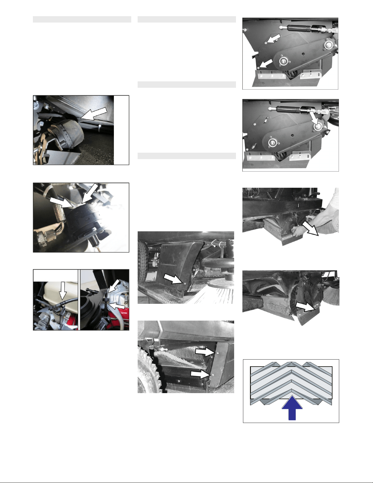
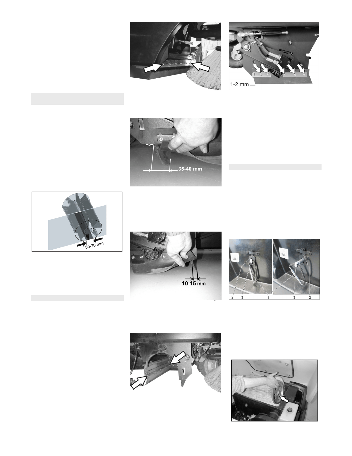
Front sealing strip
Slightly loosen retaining nuts for the
front sealing strip; to replace, unscrew.
Screw on new sealing strip without fully
tightening the nuts.
Adjust sealing strip.
Set the distance of the sealing strip to
the floor so that the bottom edge trails
behind at a distance of between 35 and
40 mm.
Tighten nuts.
Rear sealing strip
Set the distance between the sealing
strip and the floor so that the bottom
edge trails behind at a distance of be-
tween 10 and 15 mm.
If worn, replace.
Remove roller brush.
Unscrew retaining nuts for rear sealing
strip.
Screw on new sealing strip.
Side sealing strips
Slightly loosen retaining nuts for the
side sealing strip (to replace, unscrew).
Screw on new sealing strip without fully
tightening the nuts.
To set the floor clearance, insert a
sheet with a thickness of between 1 and
2 mm under the sealing strip.
Adjust sealing strip.
Tighten nuts.
Screw on side panels.
Push in the waste containers on both
the sides and lock them.
�
WARNING
Empty waste container before replacing
dust filter. Wear a dust mask when working
around the dust filter. Observe safety regu-
lations on the handling of fine particulate
material.
CAUTION
Risk of damage!
Do not rinse out the dust filter.
Turn main key to "0" and remove it.
Open the hood, insert retaining rod.
1 Filter holder handle
2 Locking
3 Axle
Pull the lock upwards.
Pull out the axle on the handle of the fil-
ter holder until the lock engages (nut in
axle).
Remove the lamella filter.
Insert new filter.
Make sure driver engages with holes on
drive side.
Check the sweeping mirror of the
sweeping roller
Adjusting and replacing sealing strips
Replacing dust filter
29EN
-
12
Push the axle inwards again so it locks
into place.
Note: Make sure when installing the new
filter that the fins are not damaged.
Lift filter case seal out of groove in the
cover.
Insert new seal.
Check tension of drive belt and V-belt of
the suction blower, also check for wear
or damage.
Chek the cup seal at the suction blower
regularly to see that it sits properly.
Loosen screws on both sides of the
panel.
Replace defective fuses.
Replace front panel.
Note: Only use fuses with identical safety
ratings.
NOTICE
The engine is equipped with an oil deficien-
cy switch. When the fill level is insufficient,
the engine switches off and can only be re-
started once the engine oil has been re-
plenished.
� DANGER
Risk of burns on account of hot surfaces!
Allow engine to cool down.
Remove the oil dipstick and check the
oil level: Minimum content 1/3.
If the oil level is less than 1/3, top up en-
gine oil until it reaches the lower edge of
the filler opening.
Wait at least 5 minutes.
Check engine oil level again.
�
DANGER
Risk of burns on account of hot surfaces!
Pull out oil dipstick.
Draw off engine oil via the oil filler neck
using 6.491-538 oil-change pump.
Fill with fresh engine oil via oil filler neck
using clean 6.491-538 oil-change
pump.
Wait at least 5 minutes.
Check engine oil level again.
Release the wing nuts on the suction
container.
Remove the filter inlay and check it.
Use either a new or cleaned filter car-
tridge in the vacuum container.
Screw on wing nut.
Remove spark-plug connector.
Unscrew and clean or dispose of spark
plug.
Screw in cleaned or new spark plug.
Insert the ignition plug into the spark
plug.
NOTICE
The machine has two hydraulic circuits:
Circuit sweeping hydraulics
Check the hydraulic oil level on the stor-
age container.
The oil level must lie between “MIN“
and “MAX“ marking.
If the oil level is too low, fill in hydraulic
oil above the fill neck on the top of the
container.
Circuit axle drive
CAUTION
This inspection may only be carried out
when the engine is cold.
Check oil level in the equalisation con-
tainer.
If required, top up oil carefully.
Replacing filter case seal
Checking drive belt
Check cup seal
Replacing fuses
Check engine oil level and top up, if
required
Change the engine oil
Cleaning and replacing the air filter
Clean and replace spark plug
Check hydraulic oil level and refill
hydraulic oil
30 EN

-
13
� Danger
Switch off engine and remove ignition key
prior to carrying out any maintenance work.
Risk of injury! Allow the machine sufficient
time to cool down before carrying out any
maintenance and repair work.
Troubleshooting
Fault Remedy
Appliance cannot be started Sit on the driver seat, the seat contact switch gets activated.
Check tank contents and oil level; refill oil and fuel.
Check the fuses.
Check battery; charge it if required.
Inform Kärcher Customer Service.
Device does not drive or drives
only slowly
Lock the freewheel lever in the bottom position (driving operation).
Inform Kärcher Customer Service.
Machine is not sweeping properly Check roller brush and side brushes for wear, replace if necessary.
Check function of bulk waste flap
Check sealing strips for wear, adjust or replace as required
Check belts of sweeping drive.
Check vacuum pressure system to see it is leak-proof.
Inform Kärcher Customer Service.
Dust gathers in the machine Empty waste container
Check suction fan drive belt
Check sealing cover on suction fan
Check dust filter, clean or replace
Do not rinse out the dust filter.
Check filter case seal
Close wet/dry flap
Check sealing strips for wear, adjust or replace as required
Inform Kärcher Customer Service.
Side brush does not turn Check the fuse.
Inform Kärcher Customer Service.
Poor cleaning performance at edg-
es
Replace side brush
Check sealing strips for wear, adjust or replace as required
Inform Kärcher Customer Service.
Side brush or roller brush switch-
on operation is not working
Check vacuum pressure system to see it is leak-proof.
Inform Kärcher Customer Service.
Insufficient vacuum performance Check filter case seal
Check sealing cover on suction fan
Check hoses of suction blower for absence of leakness.
Insert lamella filter correct; see Changing dust filter
Inform Kärcher Customer Service.
Roller brush does not turn. Remove belts or cords from roller brush
Inform Kärcher Customer Service.
31EN

-
14
Technical specifications
KM 100/100 R G KM 100/100 R LPG
Machine data
Length x width x height mm 2006 x 1005 x 1343 2006 x 1005 x 1343
Unladen weight kg 300 300
Transport weight kg 375 375
Permissible overall weight kg 520 520
Driving speed km/h 8 8
Cleaning speed km/h 6 6
Climbing capability (max.) % 18 18
Roller brush diameter mm 285 285
Roller brush width mm 710 710
Side brush diameter mm 450 450
Working width without side brushes mm 710 710
Working width with 1 side brushes mm 1000 1000
Working width with 2 side brushes (option) mm 1290 1290
Volume of waste container l 100 100
Protection type, drip-proof -- IPX 3 IPX 3
Engine
Type -- Honda, GX 270
1 cyl., four-stroke
Honda, GX 270
1 cyl., four-stroke
Cylinder capacity cm
3
270 270
Max. power kW/HP 6,6 / 9 6,6 / 9
Maximum torque at 2500 rpm Nm 19 19
Fuel type -- Petrol, unleaded Liquid gases (propellants): Butane and
propane or a mixture of butane/propane
RON 95 / EN 589
Tank content -- 6 l 11 kg / 20 litres (replacement cylinder)
Spark plug, NGK -- BPR 6 ES BPR 6 ES
Type of protection -- IP22 IP22
Battery
Type -- 12V, 44Ah 12V, 44Ah
Oil grades
Motor -- SAE 15W40 SAE 15W40
Sweeping hydraulics -- HVLP 46 HVLP 46
Axle drive -- SAE 10W-60 SAE 10W-60
Tyres
Size, front -- 4.00-4 4.00-4
Air pressure, front bar 6 6
Size, rear -- 4.00-8 4.00-8
Air pressure, rear bar 4,5 4,5
Brake
Service brake -- hydrostatic hydrostatic
Parking brake -- automatic (with spring) automatic (with spring)
Filter and vacuum system
Filter surface area, fine dust filter m
2
6,0 6,0
Category of use – filter for non-hazardous dust -- U U
Nominal vacuum, suction system mbar 12 12
Nominal volume flow, suction system l/s 50 50
Working conditions
Temperature °C -5...+40 -5...+40
Air humidity, non-condensing % 20 - 90 20 - 90
Values determined as per EN 60335-2-72
Noise emission
Sound pressure level L
pA
dB(A) 79 79
32 EN
-
15
We hereby declare that the machine de-
scribed below complies with the relevant
basic safety and health requirements of the
EU Directives, both in its basic design and
construction as well as in the version put
into circulation by us. This declaration shall
cease to be valid if the machine is modified
without our prior approval.
The signatories act on behalf of and with of
the authority of the company management.
Documentation supervisor:
S. Reiser
Alfred Kärcher SE & Co. KG
Alfred-Kärcher-Straße 28-40
71364 Winnenden (Germany)
Tel.: +49 7195 14-0
Fax: +49 7195 14-2212
Winnenden, 2021/02/01
We hereby declare that the product de-
scribed below complies with the relevant
provisions of the following UK Regulations,
both in its basic design and construction as
well as in the version put into circulation by
us. This declaration shall cease to be valid
if the product is modified without our prior
approval.
The signatories act on behalf of and with of
the authority of the company management.
Documentation supervisor:
S. Reiser
Alfred Kärcher SE & Co. KG
Alfred-Kärcher-Straße 28-40
71364 Winnenden (Germany)
Tel.: +49 7195 14-0
Fax: +49 7195 14-2212
Winnenden, 2021/02/01
Uncertainty K
pA
dB(A) 2 2
Sound power level L
WA
+ Uncertainty K
WA
dB(A) 98 98
Machine vibrations
Hand-arm vibration value m/s
2
<2,5 <2,5
Seat m/s
2
1,3 1,3
Uncertainty K m/s
2
0,2 0,2
EU Declaration of Conformity
Product: Ride-on vacuum sweeper
Type: 1.280-xxx
Relevant EU Directives
2006/42/EC (+2009/127/EC)
2014/30/EU
2000/14/EC
2014/53/EU (TCU)
Applied harmonized standards
EN 60335–1
EN 60335–2–72
EN 62233: 2008
EN 55012: 2007 + A1: 2009
EN 61000–6–2: 2005
(TCU)
EN 300 328 V2.1.1
EN 300 330 V2.1.1
EN 300 440 V2.1.1
EN 301 511 V12.5.1
Applied conformity evaluation method
2000/14/EC: Appendix V
Sound power level dB(A)
KM 100/100 R G
KM 100/100 R LPG
Measured: 95
Guaranteed: 98
Chairman of the Board of Management
Director Regulatory Affairs & Certification
Declaration of Conformity
Product: Ride-on vacuum sweeper
Type: 1.280-xxx
Currently applicable UK Regulations
S.I. 2008/1597 (as amended)
S.I. 2016/1091 (as amended)
S.I. 2001/1701 (as amended)
S.I. 2017/1206 (as amended) TCU
Designated standards used
EN 60335–1
EN 60335–2–72
EN 62233: 2008
EN 55012: 2007 + A1: 2009
EN 61000–6–2: 2005
(TCU)
EN 300 328 V2.1.1
EN 300 330 V2.1.1
EN 300 440 V2.1.1
EN 301 511 V12.5.1
Applied conformity assessment procedure
S.I. 2001/1701 (as amended): Schedule 8
Sound power level dB(A)
KM 100/100 R G
KM 100/100 R LPG
Measured: 95
Guaranteed: 98
Chairman of the Board of Management
Director Regulatory Affairs & Certification
Accessories
Side brushes 6.905-986.0
With standard bristles for indoor and out-
door areas.
Side-brushes, soft 6.906-133.0
For fine dust on inside surfaces; wetness
resistant.
Hard side-brushes 6.906-065.0
For removing stubborn dirt in the external
area; resistant to moisture.
Standard sweep roller 6.906-375.0
Resistant of wear and moisture. Universal
bristles for inside and outside cleaning.
Roller-brush, soft 6.906-533.0
With natural bristles especially for fine
dust sweeping on smooth indoor floors.
Not resistant to wetness; not for abrasive
surfaces.
Roller-brush, hard 6.906-532.0
For removing stubborn dirt in the external
area; resistant to moisture.
Dust filter 6.414-532.0
33EN