USER MANUAL
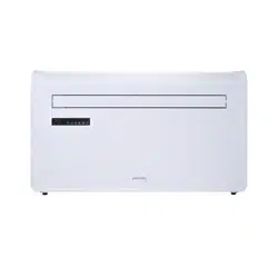
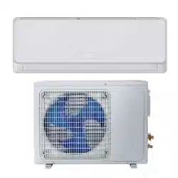
electriQ WALL MOUNTED AIR CONDITIONER
WITH HEAT PUMP AND WIFI SMART APP
IQOOL-SMART12HP
IQOOL-SMART15HP
Thank you for choosing electriQ
Please read this user manual before using this innovative Air Conditioner and keep it safe for future
reference.
Visit our page www.electriQ.co.uk for our entire range of Intelligent Electricals

SAFETY INSTRUCTIONS
SAFETY INSTRUCTIONS
2
PRODUCT OVERVIEW
4
PRODUCT DIAGRAM
4
FEATURES
5
WHATS INCLUDED
5
INSTALLATION
6
TOOLS REQUIRED
6
INSTALLATION
7
ATTACHING THE BOTTOM COVER
10
OPERATION
11
CONTROL PANEL
11
REMOTE CONTROL
11
FUNCTIONS
11
WIFI SETUP AND SMART FEATURES
13
SETUP
13
CONTROLLING YOUR DEVICE THROUGH THE APP
18
SMART SCENES / AUTOMATION
20
TROUBLESHOOTING
23
TROUBLESHOOTING
23
ERROR CODES
24
TECHNICAL DATA
25
UK SUPPORT
26

2
IMPORTANT!
AIR CONDITIONERS MUST ALWAYS BE STORED AND TRANSPORTED
UPRIGHT, OTHERWISE IRREPARABLE DAMAGE MAY BE CAUSED TO
THE COMPRESSOR; IF IN DOUBT WE SUGGEST WAITING AT LEAST 24
HOURS FOLLOWING INSTALLTION BEFORE STARTING THE UNIT.
• Carefully read the instructions before installing and/or operating the unit
• This appliance is for indoor use only.
• This unit must be only connected to a 220-240 V / 50 Hz earthed outlet.
• Installation must be in accordance with regulations of the country where the unit is
used.
• If you are in any doubt about the suitability of your electrical supply have it checked
and, if necessary, modified by a qualified electrician.
• This air conditioner has been tested and is safe to use. However, as with any electrical
appliance - use it with care.
• Disconnect the power from the appliance before dismantling, assembling or cleaning.
• Avoid touching any moving parts of the appliance.
• Never insert fingers, pencils or any other objects though the guard.
• This appliance is not intended for use by persons (including children) with reduced
physical, sensory or mental capabilities. It is also not intended for use by those with a
lack of experience and knowledge, unless they have been given supervision or
instruction concerning the use of the appliance by a person responsible for their safety.
• Do not leave children unsupervised with this appliance.
• Do not clean the unit by spraying it or immersing it in water.
• Never connect the unit to an electrical outlet using an extension cord. If an outlet is not
available, one should be installed by a qualified electrician.
• Do not operate the unit unless it has been fully installed following the guidance
provided within this manual.
• Never operate this appliance if the cord or plug is damaged. Ensure the power cord is
not stretched or exposed to sharp objects/edges.
• A damaged supply cord should be replaced by the manufacturer or a qualified
electrician in order to avoid a hazard.
• Any service other than regular cleaning or filter replacement should be performed by an
authorised service representative. Failure to comply could result in a voided warranty.
• Do not use the appliance for any purpose other than its intended use.
• Avoid restarting the air conditioner unless 3 minutes have passed since being turned off.
This prevents damage to the compressor.
• Never use the mains plug as a switch to start and turn off the air conditioner. Use the
provided ON/OFF button located on the control panel.
• The appliance should not be installed in laundry or wet rooms.
• The appliance must be installed in a room without sources of ignition (for example: open
flames, an operating gas appliance or an operating electric heater).

3
• The unit must be installed on a solid vertical wall by a competent person. The electricity
supply must only be connected after installation is complete.
• R290 refrigerant gas complies with European environmental directives.
• R290 has a low GWP (Global Warming Potential) of 3.
• These air conditioners contains about 290 g of R290 refrigerant gas.
• Do not install or store in an unventilated space with an area smaller than 15m
2
per unit.
The room must be such as to prevent stagnation of possible leaks of refrigerant gas as
there could be a danger of fire or explosion hazard should the refrigerant come into
contact with electric heaters, stoves or other sources of ignition.
• If the appliance is installed, used or stored in an unventilated room, the room must be
such as to prevent stagnation of possible leaks of refrigerant gas as there could be a
danger of fire or explosion should the refrigerant come into contact with electric heaters,
stoves or other sources of ignition.
• Refrigerant gas may be odourless.
• Do not use the product and contact the retailer for advice, if damage has occurred to the
unit which may have compromised the refrigerant system.
• Any repairs or maintenance must only be carried out on the unit by a suitably qualified
engineer. Before opening and servicing the unit the authorized engineer must be in
possession of a copy of the manufacturer’s service manual and must follow the safety
information contained within it to ensure all hazards are minimized.
• The refrigerant system should not be perforated or punctured.
Energy Saving and Unit Safety Protection Tips
• Do not cover or restrict the airflow from the outlet or inlet grills.
• Keep the filters clean. Under normal conditions, filters should only need cleaning once
every three weeks (approximately). Since the filters remove airborne particles, more
frequent cleaning maybe necessary, depending on the air quality.
• For the initial start-up set the fan speed to maximum and the thermostat to 4-5 degrees
lower than the current temperature. After, set the fan switch to low and set the
thermostat to your desired setting.
• To protect the unit, we recommend not using the cool mode when the ambient
temperature is higher than 35
o
C.
NOTE: Some pictures and information may vary from the final product. This is due to
continual product improvement.
PRODUCT OVERVIEW
4
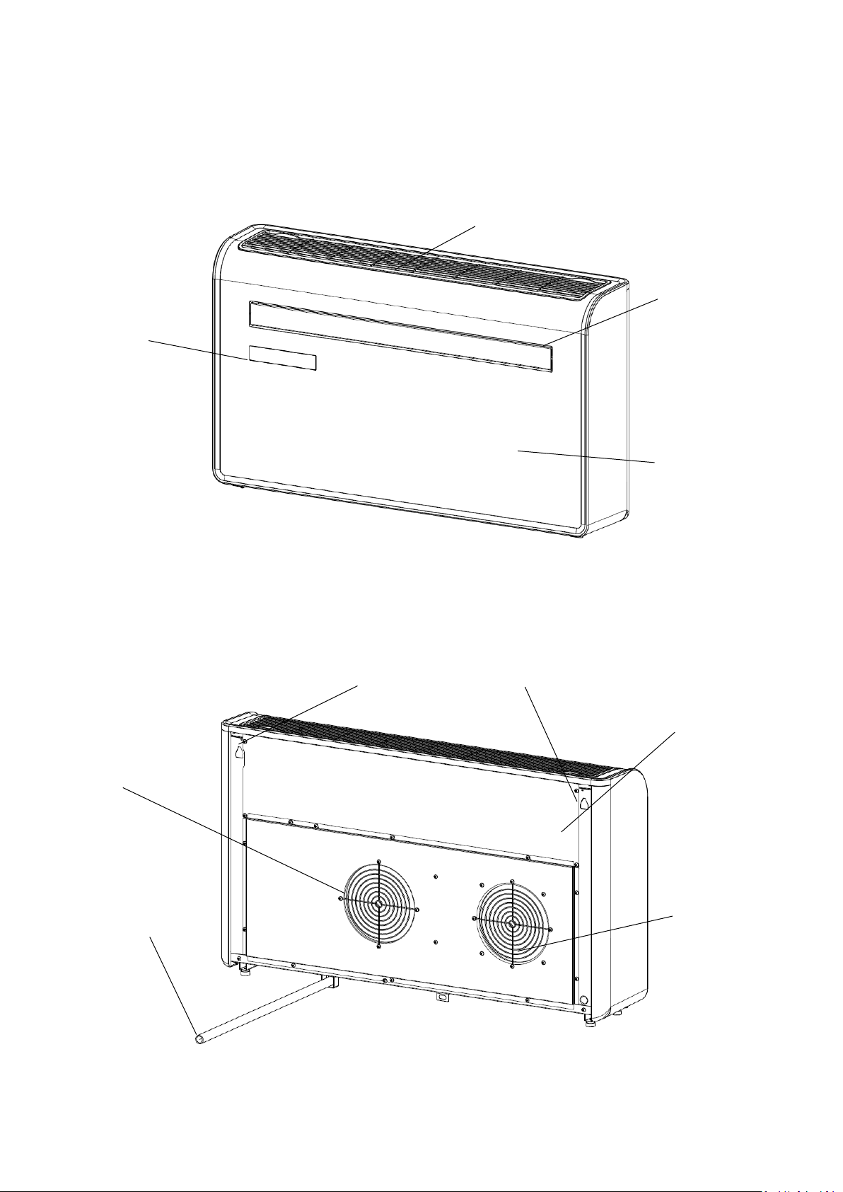
PRODUCT DIAGRAM
AIR INLET
LOUVRE
CONTROL PANEL
WALL HANGING MOUNTS
DRAINAGE PIPE
FRONT PANEL
BACK PANEL
FRONT
BACK
VENT
VENT
5
FEATURES
• Simple operation
• High and low installation options for added versatility
• Self-evaporative function with energy saving technology
• Sleek design that seamlessly fits into any style home
• Bright LED screen - Indicates temperature and current mode
• On/Off timer function - Allows you to choose when the unit operates
• WIFI App control providing additional functionality
• Three fan speeds
• Four modes to suit your every need including: Cooling/Heating/Fan/Dry.
• Silent running option, perfect for a restful night sleep
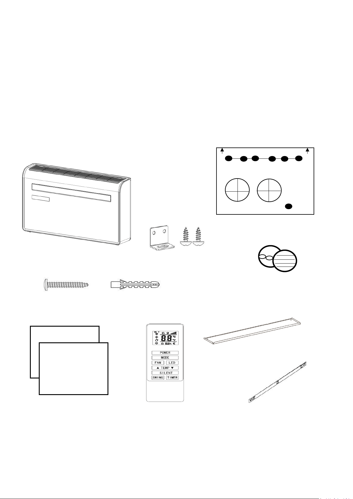
WHATS INCLUDED
AIR CONDITIONER
WALL TEMPLATE
SCREWS
WALL PLUGS
PLASTIC DUCTING
SHEET (X2)
REMOTE CONTROL
WIRED CONTROLLER AVAILABLE SEPERATELY FROM THE RETAILER UNDER REFERENCE:
IQOOLSMART12HP-WiredCtrl
WALL BRACKET
DIAGRAMS FOR ILLUSTRATIVE PURPOSES ONLY
VENT COVER ASSEMBLY (X2)
(CHAIN, INDOOR RING AND
OUTDOOR COVER
BRACKET AND
2 x SMALL SCREWS
BOTTOM COVER PLATE
INSTALLATION
6
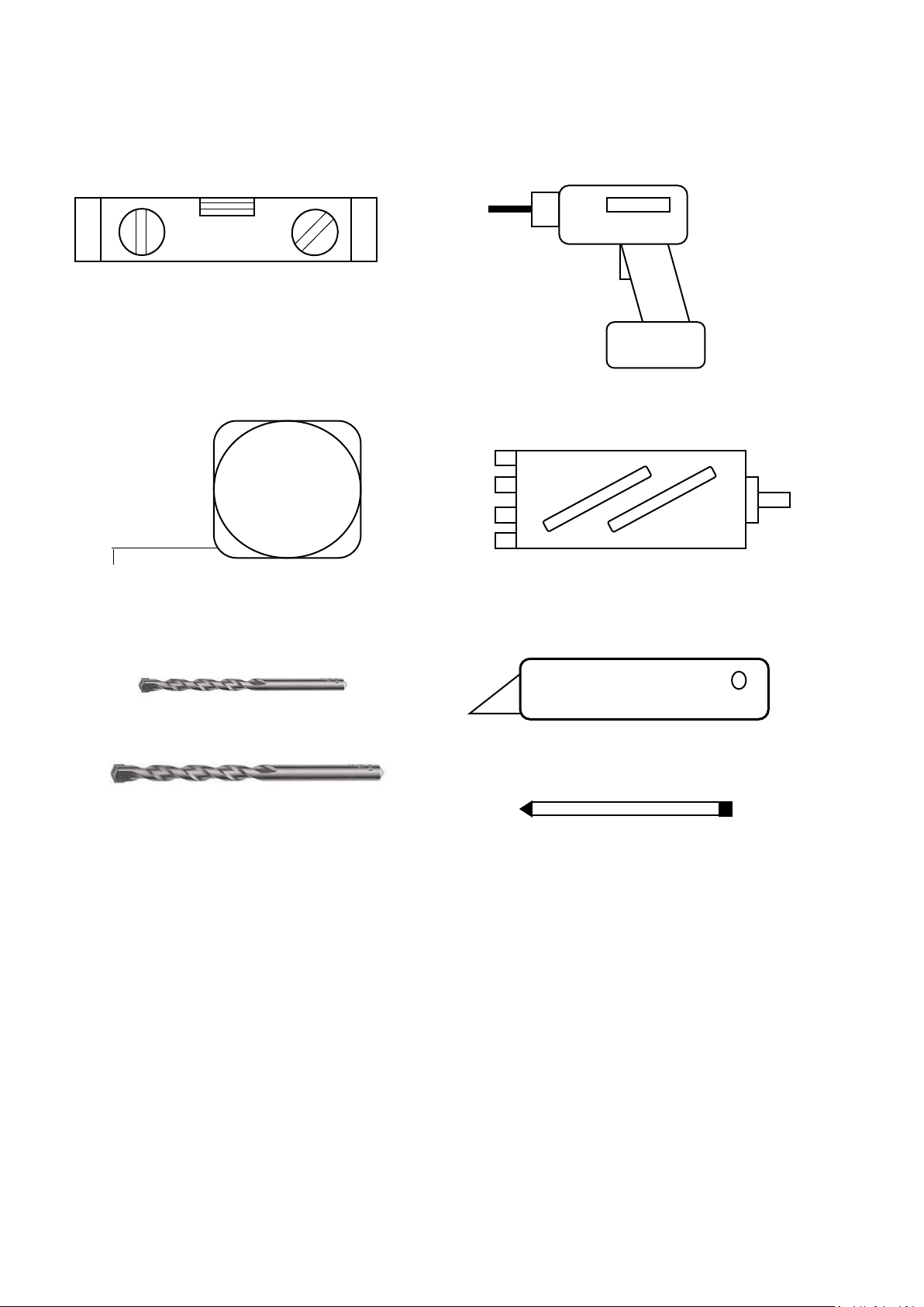
TOOLS REQUIRED
SPIRIT LEVEL
TAPE MEASURE
DRILL
180 or 182mm CORE DRILL
8mm MASONRY DRILL BIT
PENCIL
BEFORE STARTING INSTALLATION, PLEASE ENSURE YOU HAVE ALL SUITABLE EQUIPMENT
AVAILABLE AND UNDERSTAND THE STEPS INVOLVED IN INSTALLATION. IF IN ANY DOUBT,
PROFESSIONAL ADVICE SHOULD BE SOUGHT.
THE INSTALLER MUST ENSURE THAT THE PLANNED POSITION OF THE AIR CONDITIONER IS
SUITABLE, AND THAT THERE ARE NO CABLES, PIPES OR OTHER OBSTRUCTIONS, WHICH
WOULD PRESENT A DANGER AND/OR PREVENT COMPLETION OF INSTALLATION.
25mm MASONRY DRILL BIT
SHARP KNIFE
7
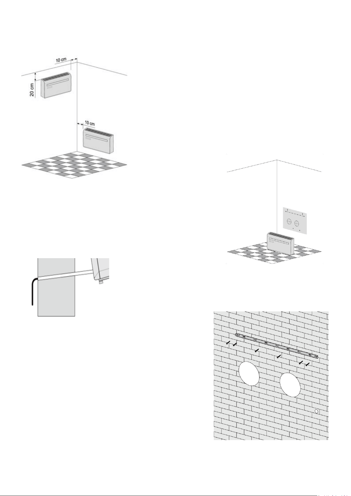
INSTALLATION
This unit must be installed on an external wall, as it vents directly
out of its rear.
Only install the unit on a flat, solid and reliable wall. Ensure that
there are no cables, pipes, steel bars or other obstructions behind
the wall.
Leave at least 10 cm of space to the left and right of the machine.
At least 20cm of space must be left above the unit to help the air
flow smoothly.
Paste the supplied installation template paper in position on the
wall, ensuring that the reference line is level using a spirit level.
The hole for the drainage pipe must be drilled using a 25mm Drill bit.
Ensure the hole is at a downward angle (min 5 degrees) so that the water
will drain correctly
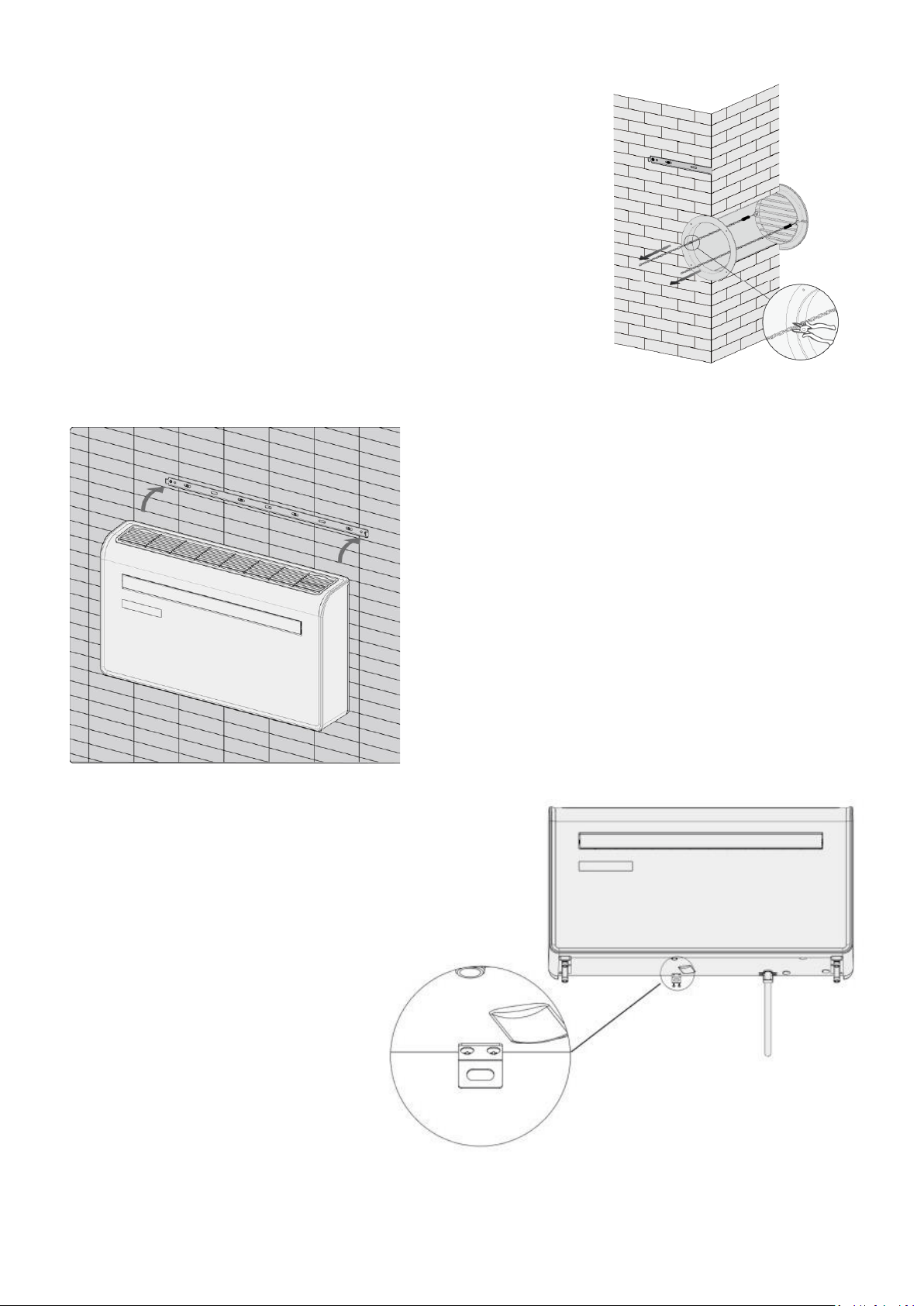
Use a 180 or 182mm core drill to drill the two holes for the units
ventillation, ensuring that both the holes are aligned with the
template.
Use the template to mark the position of the screws for the
hanging rail, using a spirit level to ensure it is straight and level.
Drill the marked holes using a suitable 8mm drill bit and insert
wall plugs. Line the hanging rail with the holes, and fix the rail
into position using the supplied screws.
Ensure that the hanging rail is securely fastened onto the wall,
and that there is no risk of the unit tipping or falling.
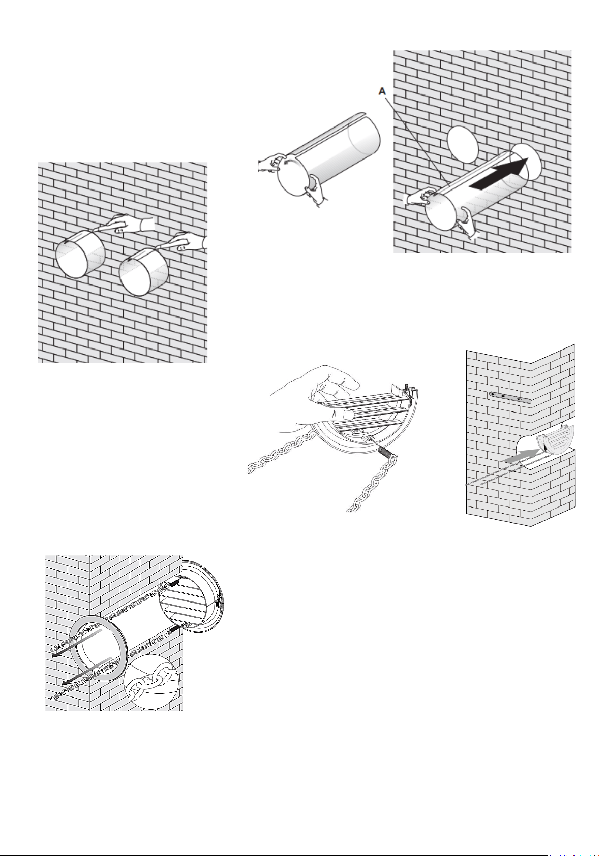
8
Roll the plastic vent sheets into a tube and
feed them from the inside into the holes
previously made. Ensure the tubes sit
flush to the interior wall.
Go outside and trim off the excess vent tube using a sharp knife,
keeping the edge as neat as possible.
Insert the indoor fixing ring from the
vent cover onto the indoor side of the
air vent. Then fold the external vent
cover in half. Attach the chains to each
side of the vent cover, before sliding
the cover outside through the vent
hole.
Expand the external cover, before tightly fixing the chains by
hooking onto the indoor fixing ring. This will hold the external
cover firmly in position. Repeat for the second vent.
9
Once the chains are fitted and secure, any excess chain should be
removed by cutting the chain.
We would also advise running a bead of exterior caulk or similar
around the external vent to help prevent water ingress.
Lift the unit onto the wall, align the hanging holes with the
hooks on the hanging rail and gently rest the unit into place.
At the same time, slide the drain pipe through the drainage
hole. If the wireless controller (Available separately) has
been purchased, it should then be installed, and connected.
NOTE: The end of the external water pipe must be placed in
an open space or drain. Avoid damage or constriction to the
drainage pipe to ensure the unit drains.
Place the bracket in position on the
under side of the unit and mark the
position of the screw hole on the wall.
Remove the bracket and drill a hole
using a 8mm drill bit before inserting a
wall plug.
Fix the bracket into position on the
underside of the unit using the 2 small
screws. Then attach the bracket to the
wall using a screw through the wall plug
previously inserted.
10
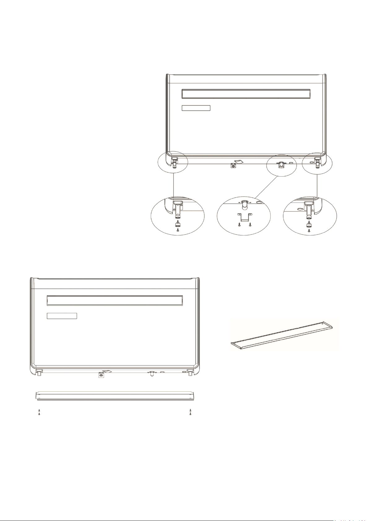
ATTACHING THE BOTTOM COVER
Note: Attachment of the bottom cover is optional. The bottom cover is designed to give the bottom of the
unit a more attractive appearance when the unit is mounted at a height and the underside is visible.
Following installation, use a
screwdriver to remove the 4 rubber
feet and the water tank braket from
the underside of the appliance.
Place the bottom cover plate in position on
the underside of the appliance, with the lips
pointing up ( small lip at the rear of the
unit)
Attach the bottom plate using the screws
removed from the feet. When fitting the
bottom plate, all 4 screws should be fitted
loosely, so the position of the plate can be
adjusted before fully securing into position.
OPERATION
11
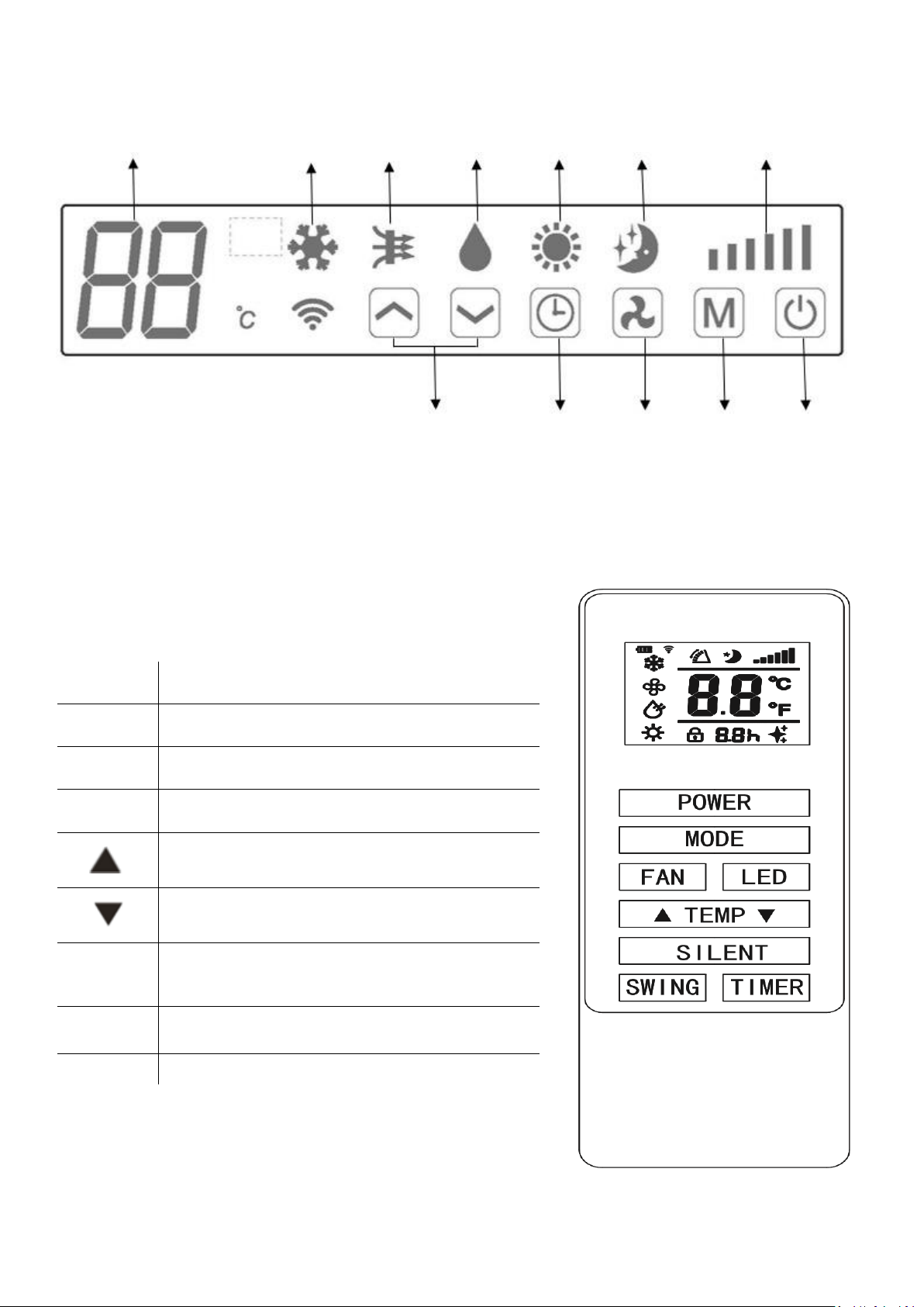
CONTROL PANEL
REMOTE CONTROL
The air conditioner can be controlled with the remote control. Two AAA-batteries are required.
NOTE: Further details of the functions can be found on the following page.
POWER
Press the POWER button to turn the machine on or
off.
MODE
Press the MODE button to switch between cooling,
heating, fan and dry modes.
FAN
Press the FAN button to change between high,
medium and low fan speeds
LED
Press to turn the LED display on the unit on and off.
Press the UP button to increase the desired
temperature or timer duration
Press the DOWN button to decrease the desired
temperature or timer duration
SILENT
Press to activate SILENT mode. In silent mode the
fan will run at low speed to minimise the operating
noise of the unit.
SWING
Press to turn the swing function on and off
(Can only be activated from the remote)
TIMER
Press the TIMER button to set the timer.
DIGITAL DISPLAY
COOLING
FAN
DRY
HEATING
SILENT
SPEED
INCREASE/DECREASE
TIMER
SPEED
MODE
POWER
12
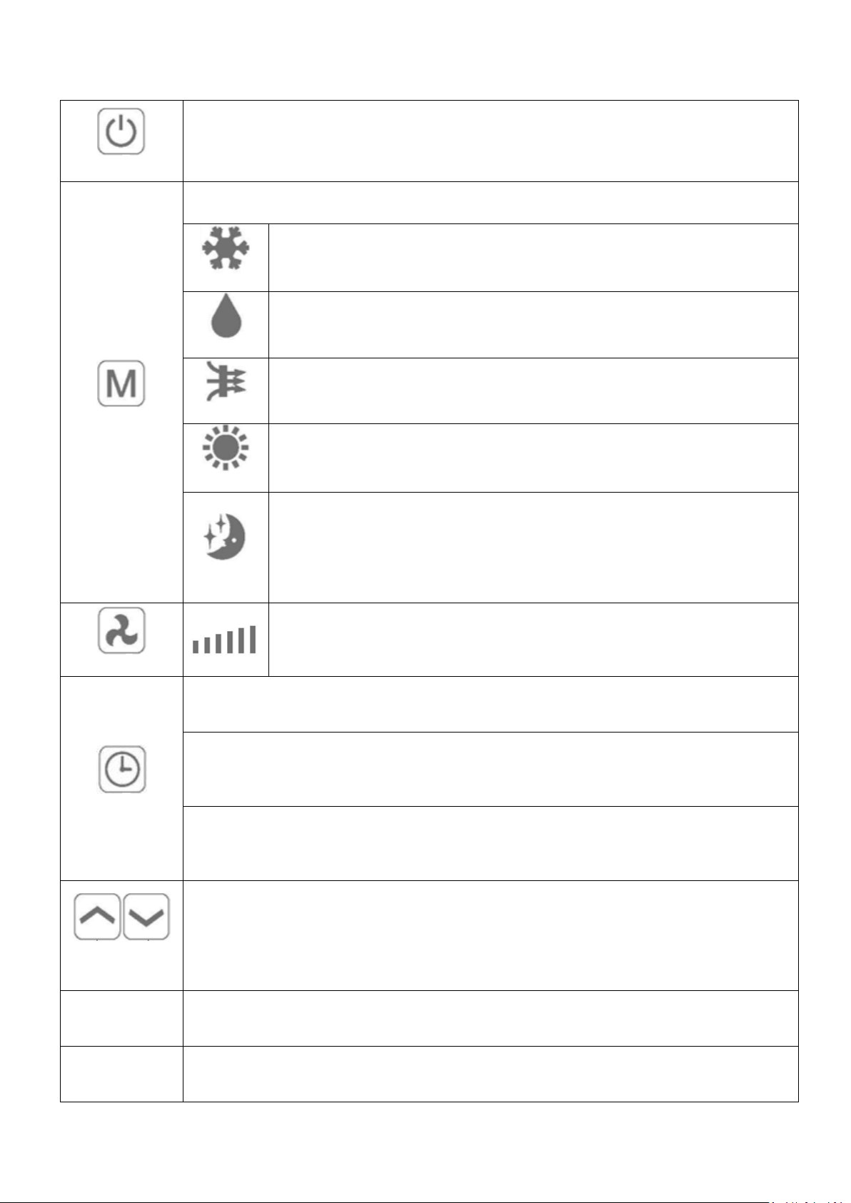
FUNCTIONS
POWER
Press “POWER” to turn the unit On or Off
MODE
Press to change between the 4 different modes. The display will show the symbol for the mode
currently selected.
COOLING
Cooling mode defaults to 22°C and will cool the air while sending warm air outside.
The desired temperature can be adjusted using the increase and decrease button
between 16°C and 30°C. The fan speed can also be adjusted using the speed button.
DRY
Dry mode will extract moisture from the air, which will be drained outside using the
installed drain pipe. The fan speed cannot be adjusted in dry mode.
FAN
In fan mode the appliance will recirculate the air within the room, and will not cool
or dehumidify. The fan speed can be adjusted using the Speed button.
HEATING
Heating mode defaults to 24°C and will heat the air while sending cool air outside.
The desired temperature can be adjusted using the increase and decrease button
between 16°C and 30°C. The fan speed can also be adjusted using the speed button.
SILENT
Silent mode can only be activated from the app or control panel by pressing the
timer and up buttons at the same time. It will only operate in cooling or heating
modes. In cooling mode, the fan speed will change to low, and the desired room
temperature will increase by 1°C after 1 hour, and a second 1°C after 2 hours,
reducing the amount of time the compressor operates. In heating mode it works
exactly the same, but the desired temperature is decreased.
FAN SPEED
Press to change the fan speed between Low, Medium and High. The fan speed
cannot be adjusted in Dry or Sleep modes.
TIMER
The air conditioner contains a 24 hour timer, which can be used to either set a delayed start, or a
set period of operation. The timers cannot be combined, although the app can be used to
program periods of operation.
SHUTDOWN TIMER: While the unit is running press the timer button, the display will flash “0” 5
times. After the 5
th
flash, use the up and down buttons to adjust the duration in 1 hout
increments between 1 to 24 hours. When the timer has elapsed, the unit will shutdown
automatically.
DELAYED START TIMER: With the unit in standby, press the timer button, the display will flash
“0” 5 times. After the 5
th
flash, use the up and down buttons to adjust the duration in 1 hout
increments between 1 and 24 hours. After the timer has elapsed, the unit will start up in the
same mode with the same settings as when it was turned off.
INCREASE AND
DECREASE
Used within cooling and heating modes to adjust the desired room temperature.
Also used while setting the timer to adjust the duration.
Press and hold the INCREASE and DECREASE buttons at the same time to change the display on
the control panel between farenheit and Celcius. Note the display on the remote cannot be
changed.
SWING MODE
After machine turns on, press the “SWING” button, louver will swing continuously up and down;
by pressing the button again the movement will stop and the louver remain in that position. Swing
mode can only be adjusted from the remote, and will initially be turned on by default.
COMPRESSOR
PROTECTION
There is a 3 minutes delay on power on. In order to protect the life of the compressor and
electronic components please do not switch on the unit for at least 5 minutes after you turned the
unit off.
TROUBLESHOOTING
13
WIFI SETUP
BEFORE YOU START
• Ensure your router provides a standard 2.4ghz connection.
• If your router is dual band ensure that both networks have different network names (SSID). The provider
of your router / Internet service provider will be able to provide advice specific to your router.
• Place the air conditioner as close as possible to the router during setup.
• Once the app has been installed on your phone, turn off the data connection, and ensure your phone is
connected to your router via wifi.
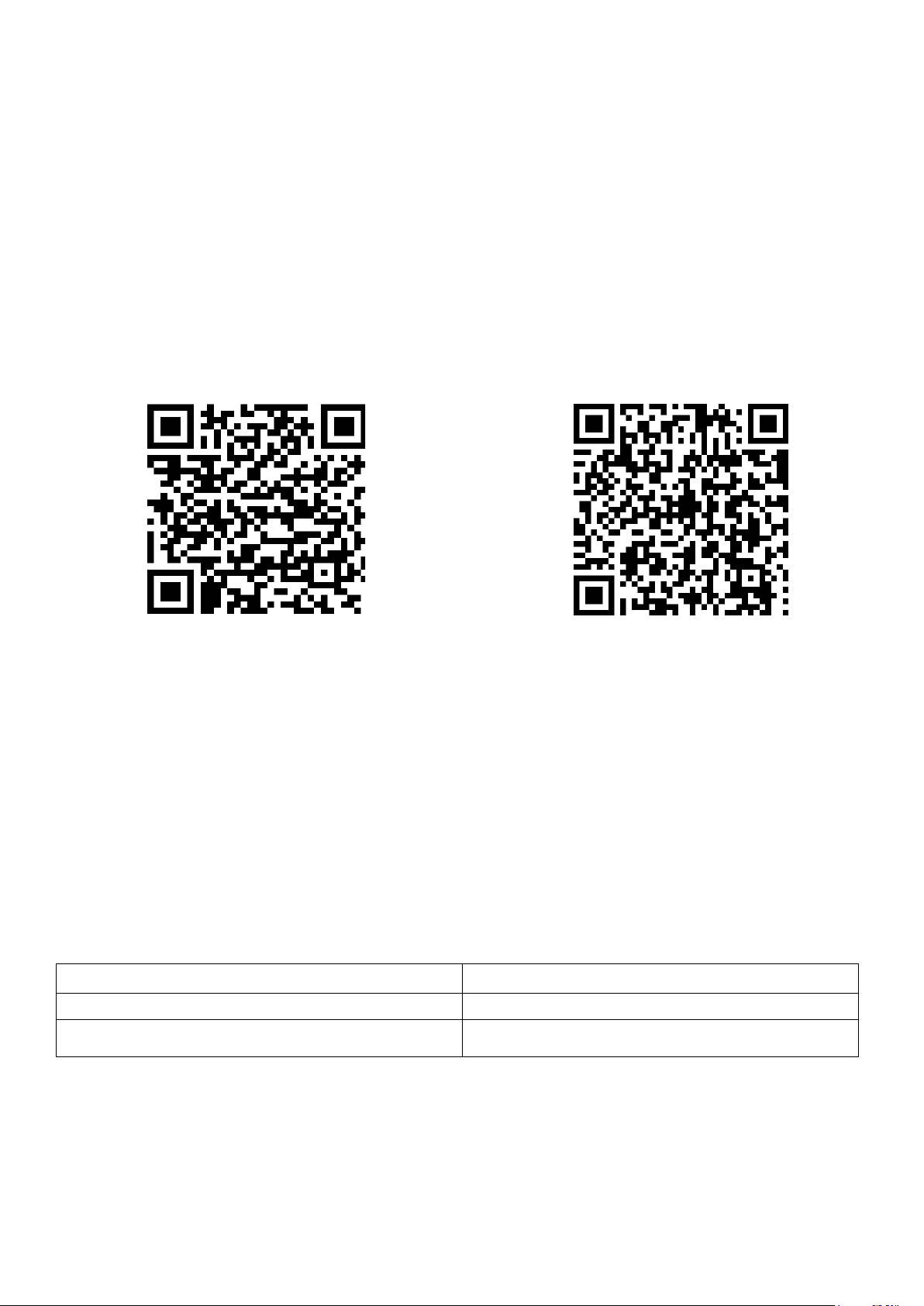
DOWNLOAD THE APP TO YOUR PHONE
Download the ”TUYA SMART” app, from your chosen app store, using the QR codes below, or by
searching for the app in your chosen store.
Android IOS
CONNECTION METHODS AVAILABLE FOR SETUP
The air conditioner has two different setup modes, Quick Connection and AP (Access Point). The
quick connection is a quick and simple way to set the unit up. The AP connection uses a direct local
wifi connection between your phone and the air conditioner to upload the network details.
Before starting the setup, with the air conditioner plugged in, but turned off, press and hold the Fan
Speed button on the air conditioner for 5 seconds (until you hear a bleep) to enter the wifi connection
mode. Please note the WIFI mode cannot be adjusted from the remote.
Please ensure your device is in the correct WIFI connection mode for the connection type you are
attempting, the flashing of the WIFI light on your air conditioner will indicate this.
Connection Type
Frequency of Flashes
Quick Connection
Flashes twice per second
AP (Access Point)
Flashes once per three seconds
CHANGING BETWEEN CONNECTION TYPES
To change the unit between the two WIFI connection modes, hold the Fan Speed button on the air
conditioner for 3 seconds.
14
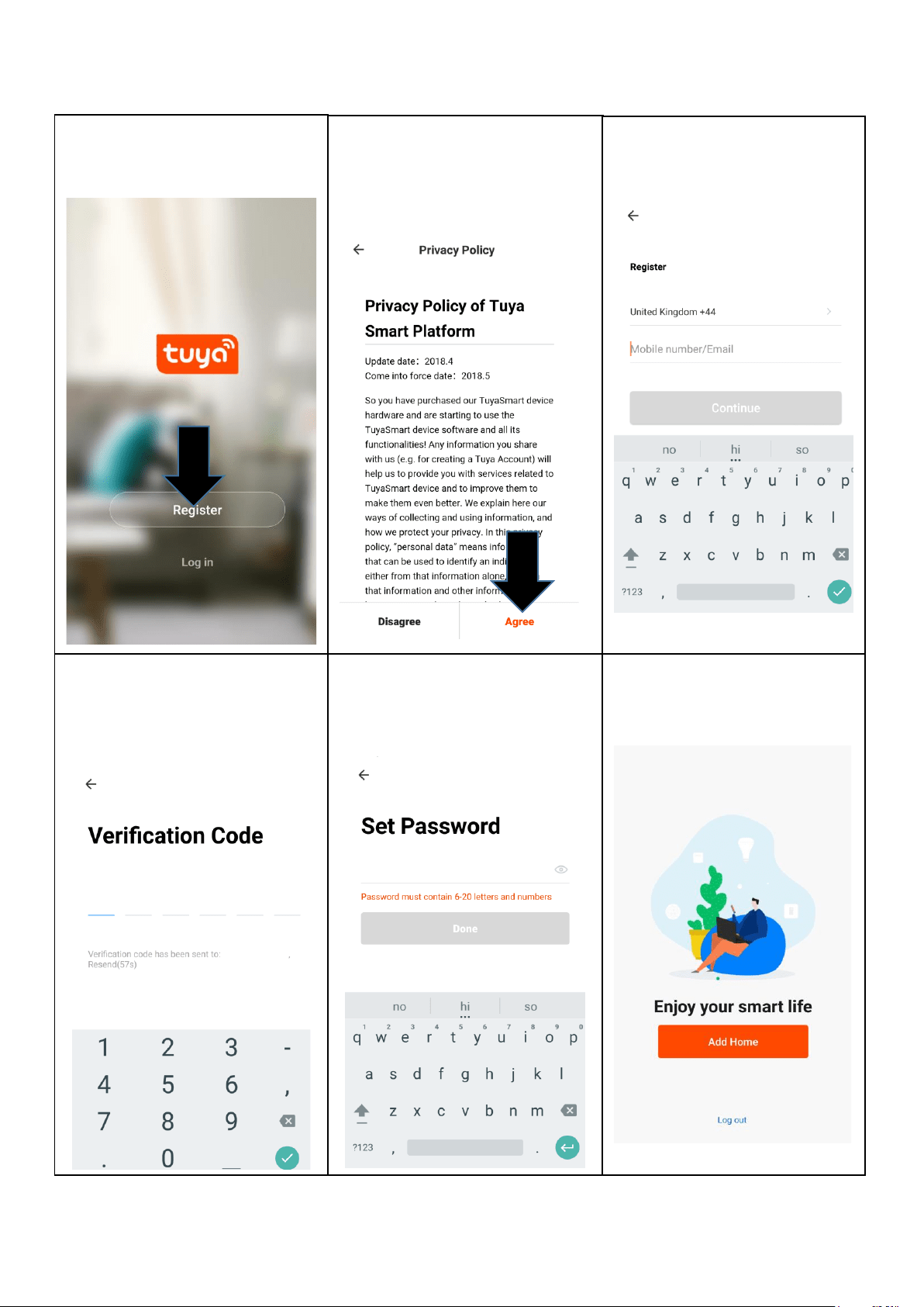
REGISTER THE APP
1. Press on the register button
at the bottom of the screen.
2. Read the Privacy policy
and press the Agree
Button.
3. Enter your email address or
phone number and press
continue to register.
4. A verification code will be
sent by the method selected
in step 3. Enter the code into
the app.
6. The app is now registered.
It will automatically log you
in following reqistration.
5. Type in the password you
would like to create. This
needs to be 6-20 characters,
with letters and numbers.
15
SETTING UP YOUR HOME WITHIN THE APP
TUYA is designed so it can work with a large number of compatible smart devices within your
home. It can also be set up to work with multiple devices within different houses As such during
the setup process, the app requires that different areas are created and named to allow easy
management of all your devices. When new devices are added, they are assigned to one of the
rooms you have created.
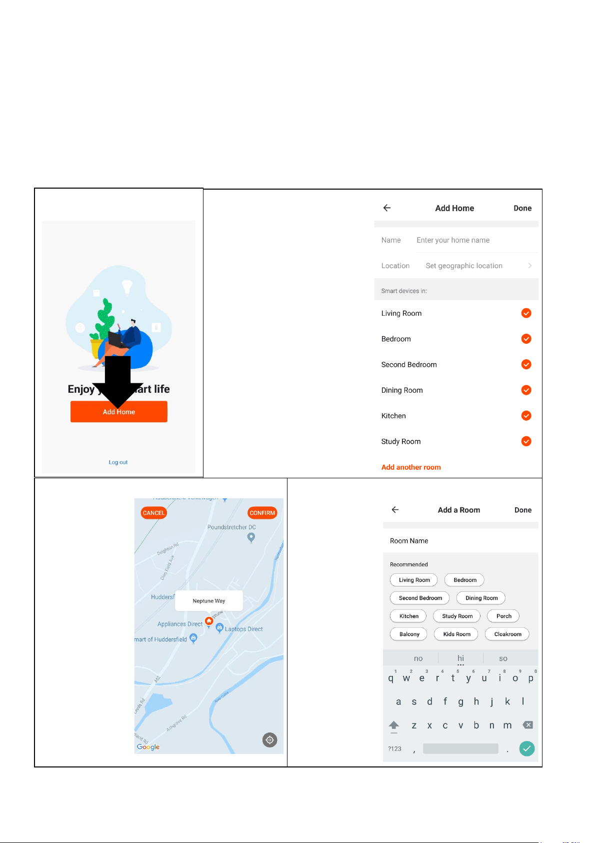
CREATING ROOMS
1. Press on the ADD HOME
button.
2. Type in a name for your
home,
3. Press on the location button
to select the location of your
home. (See SETTING
YOUR LOCATION below)
4. New rooms can be added
by pressing the ADD
ANOTHER ROOM option at
the bottom. (See ADD
ANOTHER ROOM below)
5. Untick any rooms that are
not required on the app.
6. Press DONE in the top right
corner.
SETTING YOUR LOCATION
Use your finger to
move the orange
HOME symbol.
When the symbol
is in the
approximate
location of your
home, press the
confirm button in
the top right
corner.
ADD ANOTHER ROOM
Type in the
name of the
room, and
press Done in
the top right
corner
16
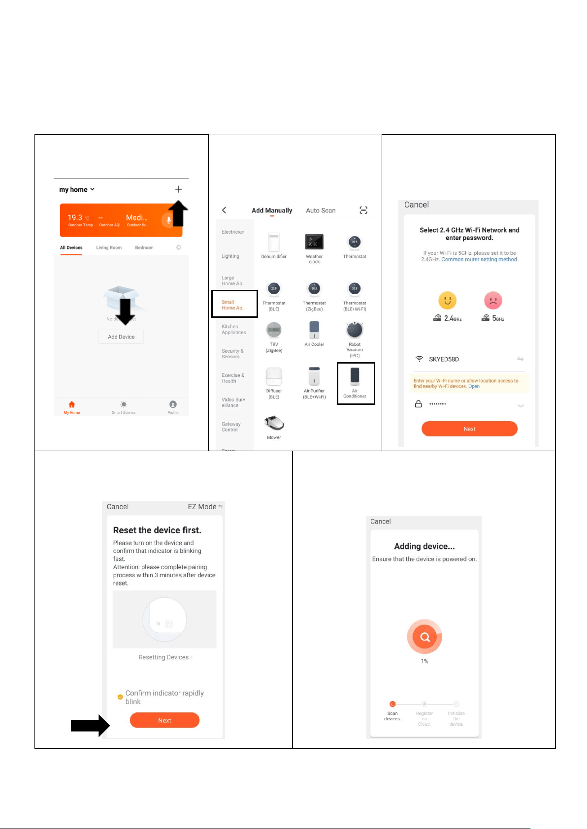
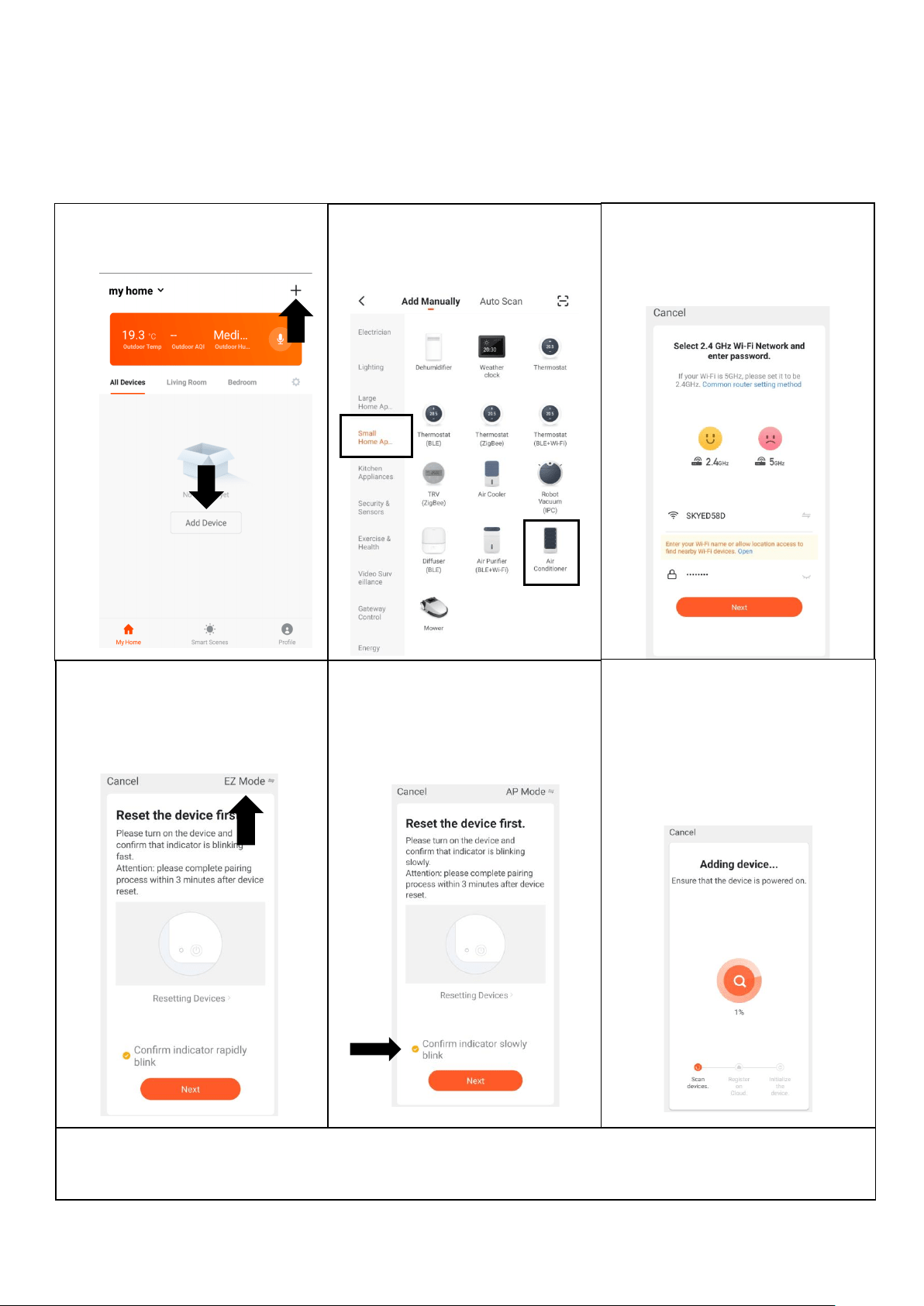
CONNECTING USING QUICK CONNECTION
Before initiating the connection, make sure the unit is in standby mode, with the WIFI light flashing
twice per second. If not follow the instructions for changing the connection mode. Also ensure
your phone is connected to the WIFI network. (We advise turning mobile data off during setup)
2. Select the type of device
as “Air Conditioner” in the
“Small Home Appliance”
tab.
5. This will then transfer the settings to the air
conditioner. Wait for this to complete. If this fails,
retry. If still unsuccessful please review the
troubleshooting section for further help.
1. Open app and press “+” to
add device, or use the add
device button
3. Ensure the correct network is
shown and that the password
is correct before pressing
next.
4. Ensure the WIFI light on the air conditioner is
flashing twice per second,tick the box to
confirm the speed of flashing and press Next.
17
CONNECTING USING AP MODE (ALTERNATIVE METHOD)
Before initiating the connection, make sure the unit is in standby mode, with the WIFI light flashing
once per second. If not follow the instructions for changing the WIFI connection mode. Also ensure
your phone is connected to the WIFI network. (We advise turning mobile data off during setup)
1. Open app and press “+” to
add device, or use the add
device button
Once the connection process has completed, go back to the network settings on your phone to ensure
your phone has reconnected to your WIFI router.
2. Select the type of device
as “Air Conditioner” in the
“Small Home Appliance” tab.
3. Ensure the correct network is
shown and that the password
is correct before pressing
next.
4. Press on the EZ mode
button in the top right of the
screen, and use the drop
down menu to select AP
Mode.
5. Ensure the WIFI light on the
air conditioner is slowly
flashing, tick the box to
confirm the speed of
flashing and press Next.
6. This will then transfer the
settings to the air conditioner.
Wait for this to complete. If
this fails, retry. If still
unsuccessful please review
the troubleshooting section for
further help.

18
CONTROLLING YOUR DEVICE THROUGH THE APP
THE HOME SCREEN
Each device has its own entry on the home screen to allow the user to either quickly turn the unit on or off,
or to enter the device screen to make other changes.
DEVICE SCREEN
Change Home: If you
have a number of units at
different houses, you can
change between them
Add Device: Add a device
to the app, and go through
the setup process.
Environmental
information: Provides
outdoor temperature and
humidity based on the
location details entered
Rooms: Use to view the
units set up within each
room
Smart Scene: Allows you
to program intelligent
behaviour based on the
internal and external
environment
Add Device: Add a device
to the app, and go through
the setup process.
Room Management:
Allows rooms to be added,
removed or renamed.
Profile: Provides the
option for changing
settings, and adding
devices using a QR code
provided by a friend.
ON / OFF Button: Use to
quickly turn the unit on or
off.
Name of Air Conditioner:
Press to enter the Device
Screen
19
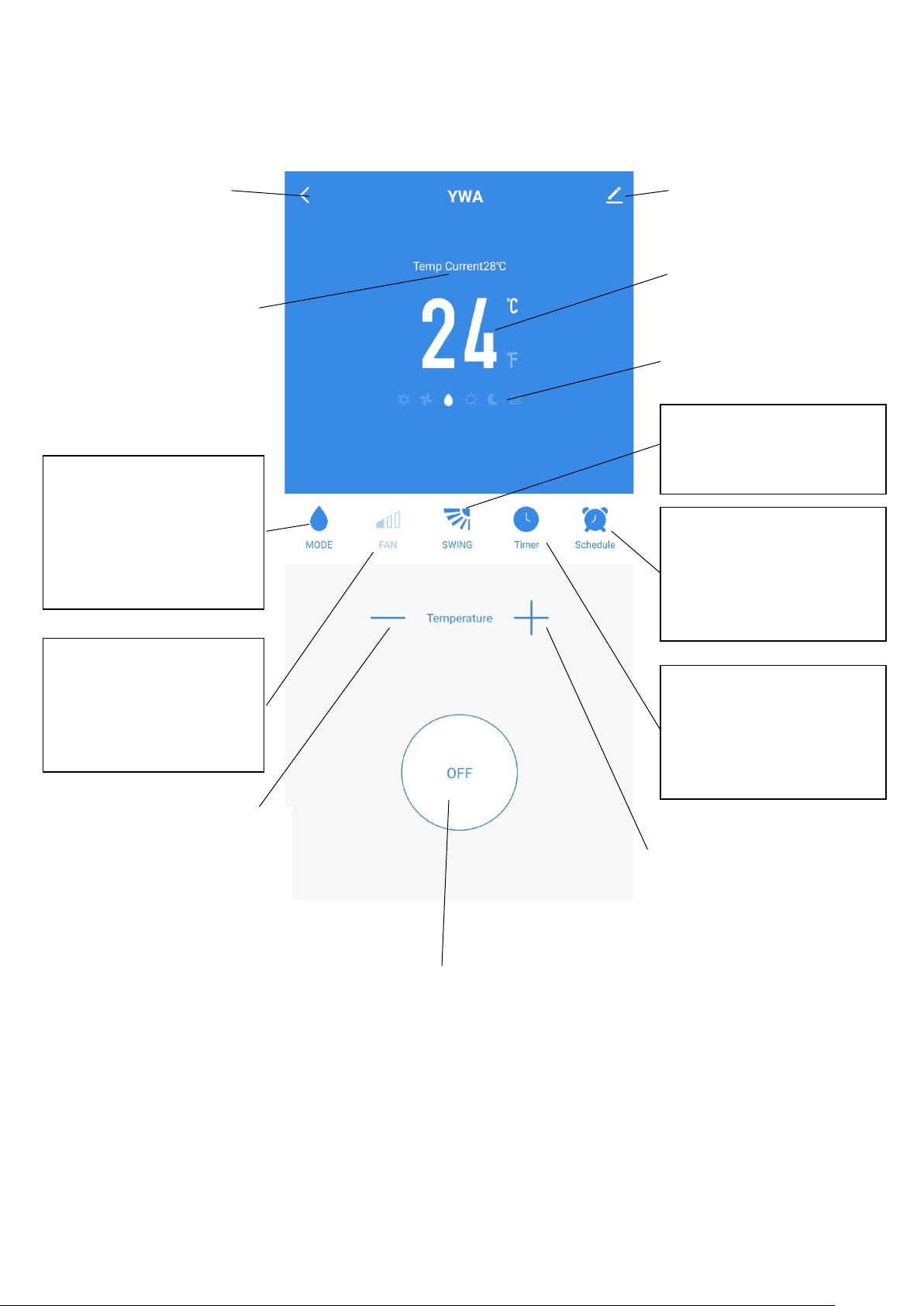
DEVICE SCREEN
The device screen is the main control screen for the air conditioner, providing access to the controls to
amend the functions and settings
*Due to continuous development of the app, the layout and available features may be subject to change.
ON / OFF Button: Use to
turn the unit on or off.
Edit Name: Use to
change the name of the
air conditioner.
Desired Temperature UP
Button: Use to increase the
desired temperature.
Current Room
Temperature: Displays the
current room temperature
Back: Returns to the
Home Screen
Desired Temperature
Down Button: Use to
decrease the desired
temperature
MODE:
Change the operating mode
of the air conditioner
between Cooling, Heating,
Dehumidify and Fan
SPEED:
Use to change the Fan speed
between Low, Medium and
High. Note this cannot be
changed in dehumidify mode.
TIMER:
Use to add an off timer while
the unit is running, or an on
timer while the unit is
turned off
Desired Room
Temperature: Displays the
desired room temperature
Current Mode: Shows the
mode the air conditioner is
currently in.
Desired Temperature UP
Button: Use to increase the
desired temperature.
SWING:
Use to turn the oscillating
swing function on and off.
SCHEDULE:
Use to add a set a scheduled
operation. A number of
these can be combined to
specify automatic operation
20
SMART SCENES
Smart Scenes is a powerful tool providing the option to customise the operation of the air conditioner based
both on conditions within the room and outside influences. This gives the user the option of specifying
much more intelligent actions. These are split into two catagories Scene and Automation.
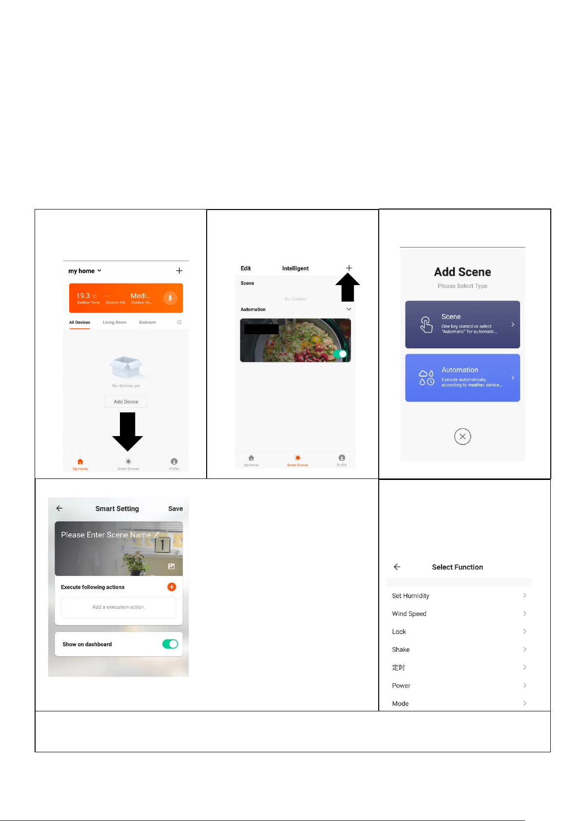
SCENE
Scene allows for a one touch button to be added to the Home screen. The button can be used to change a
number of settings in one go, and can change all the settings within the unit. A number of scenes can
easily be setup, allowing the user to easily change between a number of preset configurations.
Below is an example of how to set up a scene:
1. Press on the Smart Scene
tab at the bottom of the
Home screen
3. Select Scene to create a
new Scene
2. Press on the Plus in the top
right corner to add a smart
scene.
4. Press the Pen next to
“Please Enter Scene Name” to
input the name for your Scene
Show on Dashboard: Leave
this on if you require the scene
to be displayed as a button on
the Home Screen
Press the Red Plus to add the
action required. Then select
the air conditioner from the list
of devices.
5. Chose the function, set the
value for the function, and
then press the back button in
the top right corner, to return
to the previous screen.
6. Once all the functions required have been added, press the Save button in the top right corner to
finalise and save your new Scene
21
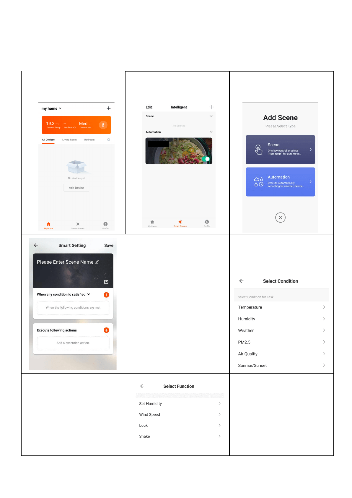
AUTOMATION
Automation allows an automatic action to be set up for the device. This can be triggered by the Time,
indoor temperature, humidity of the room, weather conditions, and a range of other influences.
1. Press on the Smart Scene
tab at the bottom of the
Home screen
2. Press on the Plus in the top
right corner to add a smart
scene.
3. Select Automation to
create a new Automation
Scene
4. Setup is very similar to the scene
setup on the previous page, and
includes an extra section for
specifying a trigger for the scene to
start.
Press the Pen next to “Please Enter
Scene Name” to input the name for
your Scene
Press the Red Plus next to “When
any condition is satisfied” to add the
trigger
Press the Red Plus next to “Execute
following actions” to add the action
required. Then select the air
conditioner from the list of devices.
6. Chose the function, set
the value for the function,
and then press the back
button in the top right corner,
to return to the previous
screen.
5. Select the condition when the
automation should start. A
number of triggers can be
combined.
7. Once all the functions required
have been added, press the
Save button in the top right
corner to finalise and save your
new scene.
The automation is now set up, it
can be turned on and off using
the toggle on the image shown
on step 2.
22
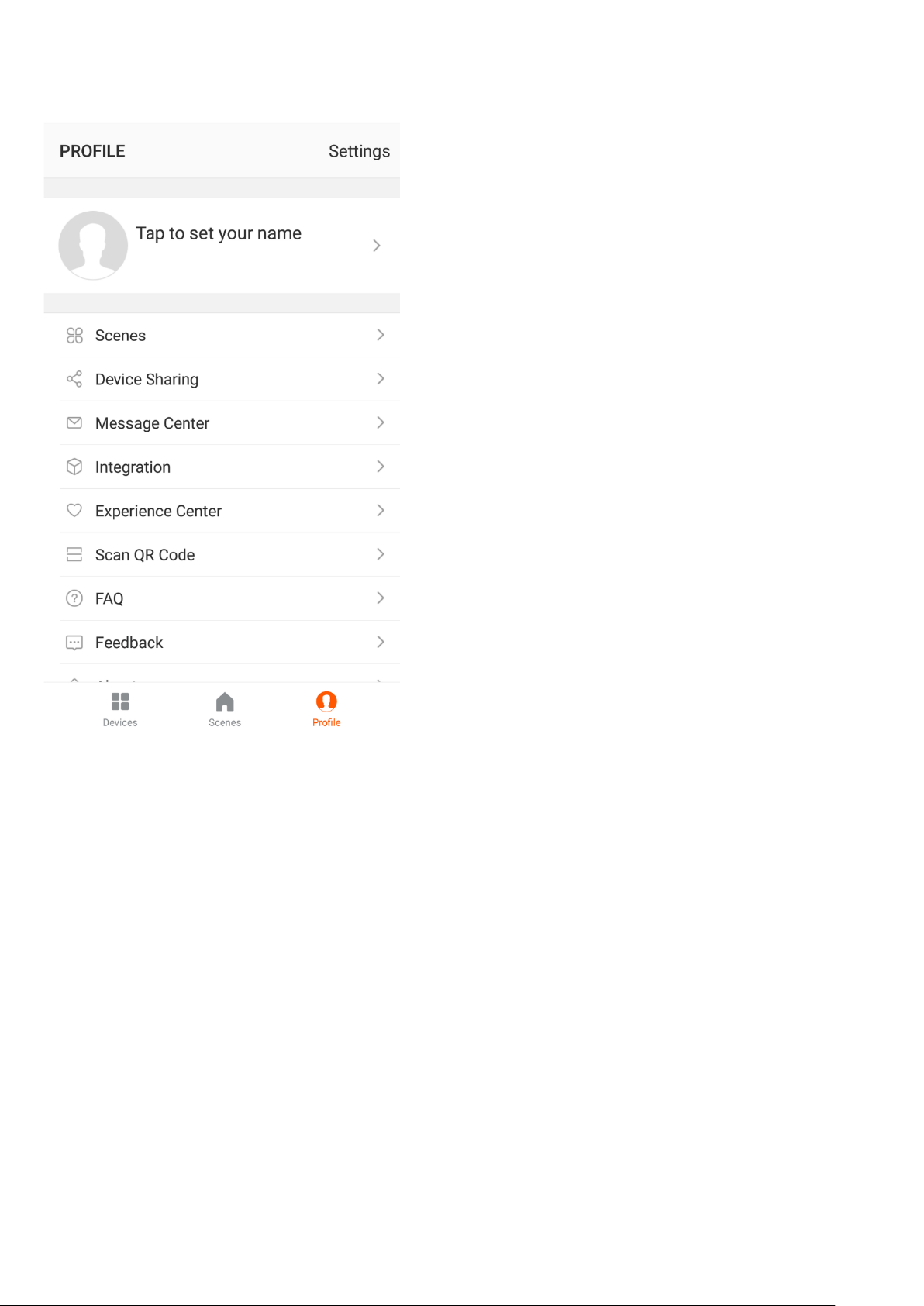
PROFILE TAB
The profile tab gives you the option to edit both your detail,
and use the added features of the unit.
CHANGING THE NAME OF YOUR DEVICE
When in any of the device screens further settings for the
device can be accessed, by pressing on the three dots in
the top right hand corner. The top option within this allows
you to change the name of the device to something relevant
to the use of the product, such as “Living Room Air
Conditioner”. Within the menu, you also have the option of
setting up a pattern lock or change your password.
DEVICE SHARING
This allows you to share access to the controls of your air
conditioner with friends and family.
INTEGRATION
This allows the unit to be integrated with your favourite
home automation hardware such as Google Home and the
Amazon Echo.
CONNECTION TROUBLESHOOTING
1. Check whether the device is powered on and is in the correct WIFI connection mode, if not please refer
to the CHANGING BETWEEN CONNECTION MODES section on page 12.
2. Ensure the WIFI password has been entered into the app correctly (Case sensitive)
3. Check that the phone is connected to the WIFI you are connecting the device to.
4. Ensure the network you are connecting it to is 2.4Ghz (5Ghz WIFI networks are not supported), and that
there is a strong WIFI signal to the item.
5. If your router is dual band, ensure that the 2.4ghz network has a different network name (SSID). Further
advice on changing router settings will be available from your Internet service provider / Router
manufacturer.
6. Check the settings on the router. Encryption should be WPA2-PSK and authorisation type should be set
to AES
7. Try using the alternative connection method. i.e. If connection is failing when attempting to connect
through CF mode, try AP mode.
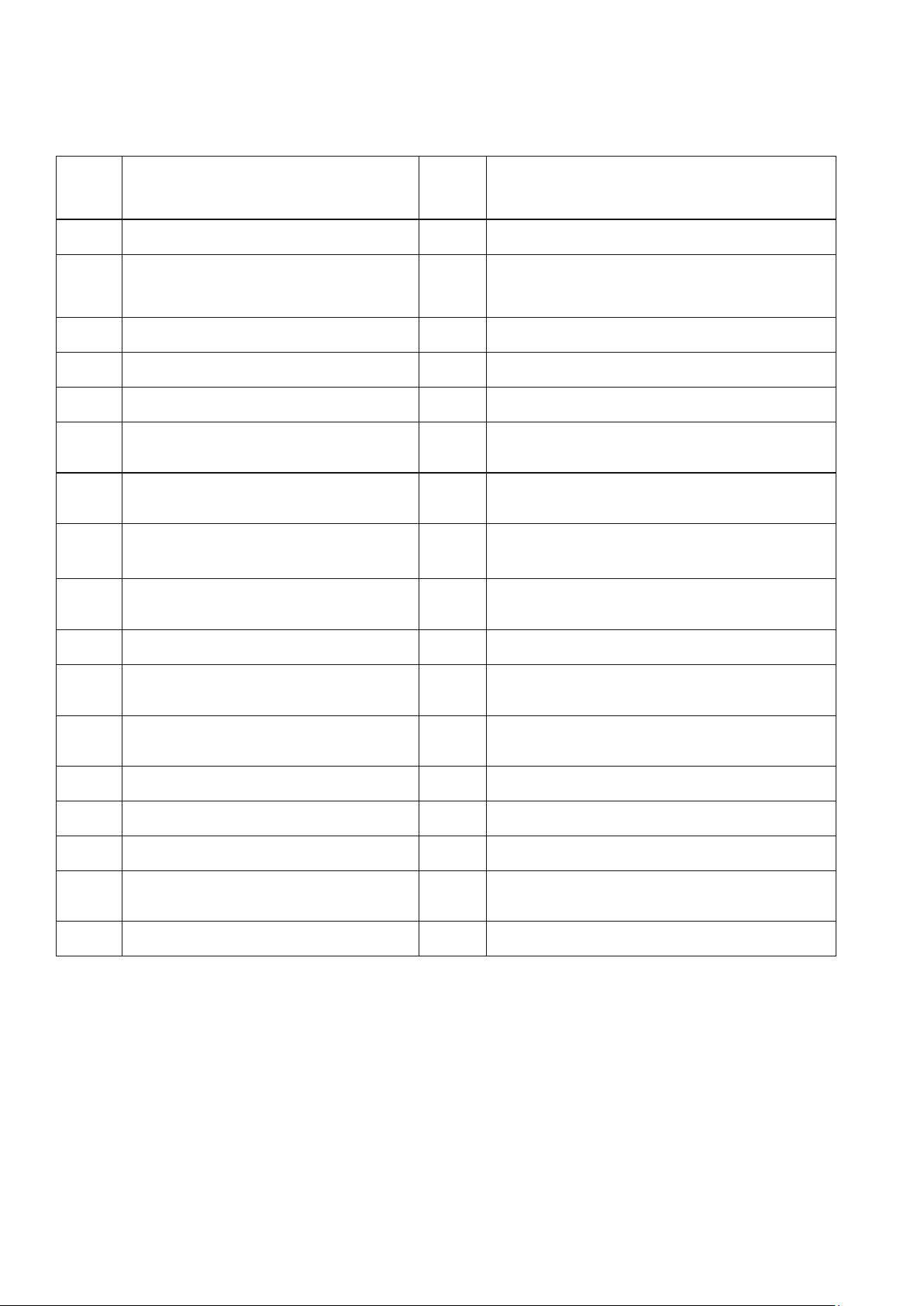
23
Do not repair or disassemble the air conditioning. Unqualified repair will invalidate the warranty and may lead to
failure, causing injuries and property damage. Only use it as directed in this user manual and only perform
operations advised here.
Problem
Reasons
Solutions
The air conditioner does
not work.
There is no electricity.
Check the unit is plugged in, and the socket
is working normally.
The ambient temperature is too low or
too high
Only use to use the machine with a room
temperature between 7 and 35°C
In cooling mode, the room temperature
is lower than the desired temperature;
in heating mode, the room temperature
is higher than the desired temperature.
Adjust the desired room temperaure
In dehumidification (dry) mode, the
ambient temperature is low.
Ensure that the room temperature is above
17°C for dry mode.
There is direct sunlight.
Use curtains to reduce heat from the sun
The cooling or heating
effect is poor
Doors or windows are open; there are a
lot of people; or in cooling mode, there
are other sources of heat (e.g. fridges)
Close doors and windows; increase air
conditioning power
The filters screen is dirty.
Clean or replace the filter screen.
The air inlet or outlet is blocked.
Clear obstructions; make sure the unit is
installed as per the instructions
The air conditioner is
leaking
The unit is not straight
Use a spirit level to check the unit is
horizontal, if not remove from the wall and
straighen
The drain pipe is blocked
Check the drain pipe to ensure it is not
blocked or constricted.
Compressor does not
work.
Overheat protection operational
Wait for 3 minutes until the temperature is
lowered, and then restart the machine.
The remote control does
not work.
The distance between the machine and
the remote control is too far.
Let the remote control get close to the air
conditioner, and make sure that the remote
control directly faces to the direction of the
remote-control receiver.
The remote control is not aligned with
the direction of the remote-control
receiver.
Batteries are dead.
Replace batteries.
If problems not listed in the table occur or recommended solutions do not work, please contact the service centre.
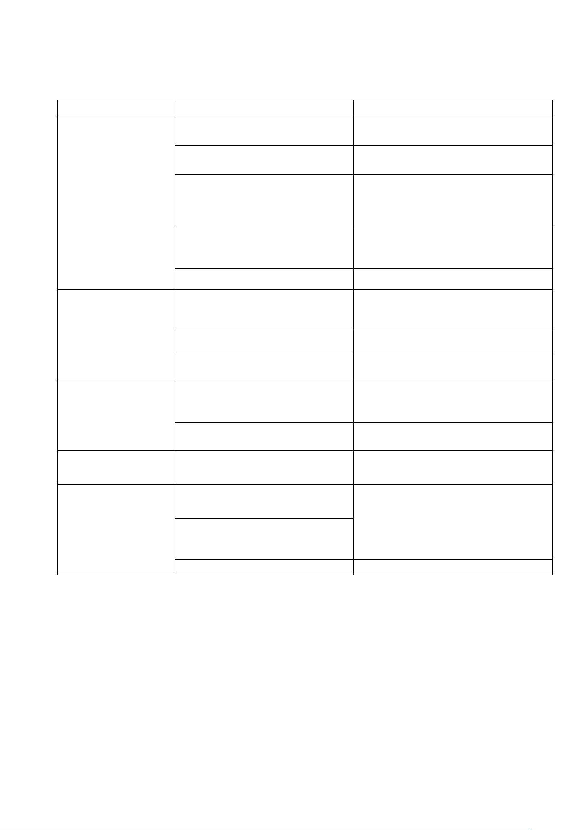
24
ERROR CODES
Fault
Code
Fault Description
Fault
Code
Fault Description
F1
Compressor IPM error
FE
EE error (condenser circuit)
F2
PFC/IPM error
PA
Return air sensor temperature abnormal
protection
F3
Compressor start error
P1
Over-heat protection on top of compressor
F4
Compressor running out of step
PE
Abnormal refrigerant circulation
F5
Location detection loop failure
PH
Exhaust temperature protection
FA
Phase current overcurrent
protection
PC
Coil tube overload protection
(condenser circuit)
P2
Dc bus voltage Undervoltage
protection
E3
DC fan Feedback failure (evaporator circuit)
E4
Communication error ( evaporator
circuit and condenser circuit )
P6
Coil tube overload protection (evaporator
circuit)
F6
PCB communication error
P7
Defrost protection on coil tube (evaporator
circuit)
P3
AC Input voltage protection
E2
Sensor error on indoor coil tube
P4
AC over-current protection
E1
Temperature sensor error (evaporator
circuit)
P5
AC undervoltage protection
P8
Zero-crossing fault detection (evaporator
circuit)
F7
Coil sensor error(condenser circuit)
EE
EE error (evaporator circuit)
F8
Sensor on suction pipe error
E5
Water-splash motor error
E0
Sensor on discharge pipe error
E8
Fan feedback fault
E6
Temperature sensor error
(condenser circuit)
FL
Water-full protection
E7
Fan motor error (condenser circuit)
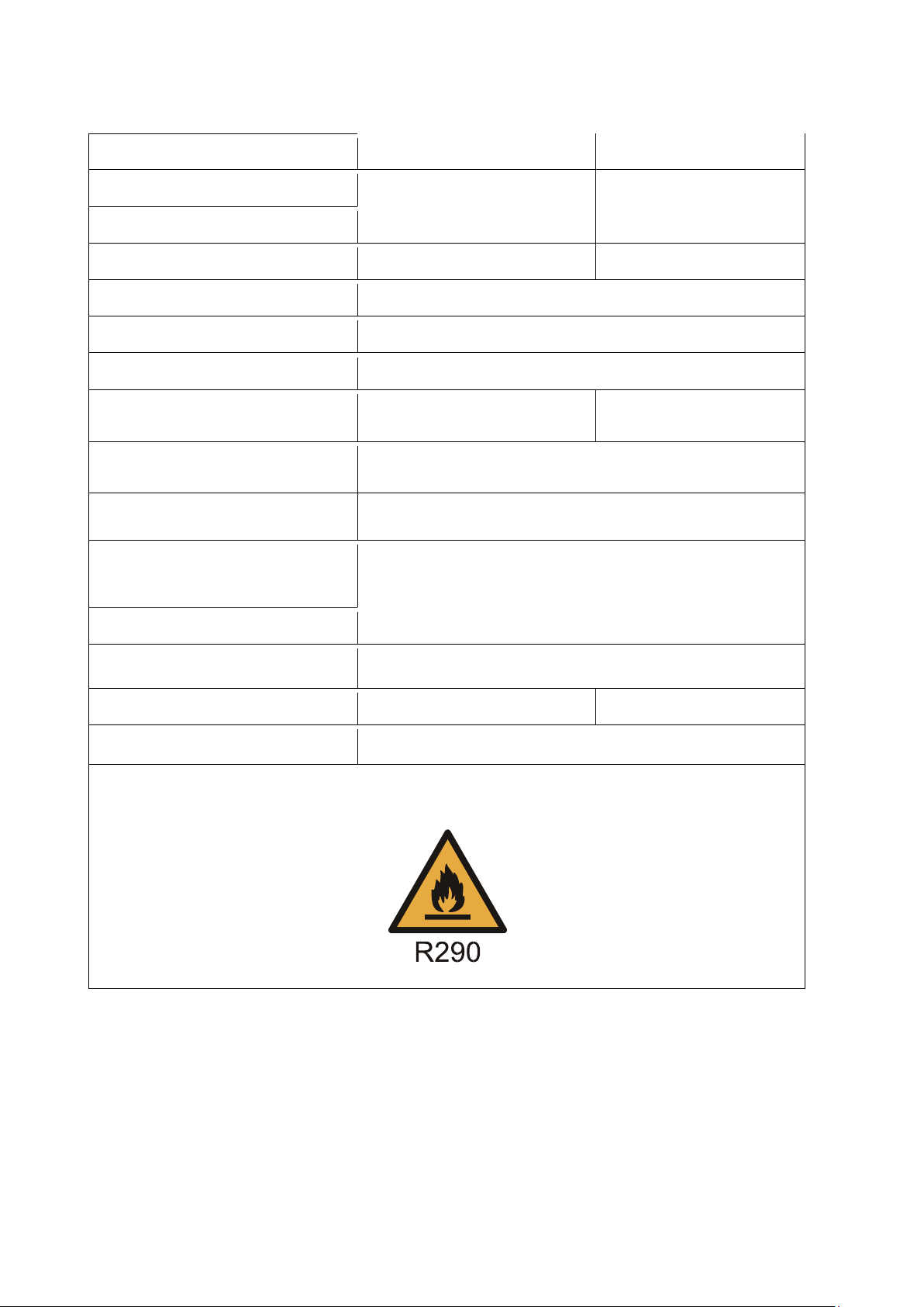
TECHNICAL DATA
25
MODEL
IQOOL-SMART12HP
IQOOL-SMART15HP
Capacity Cooling/Heating
2.93 / 2.63KW
3.5 / 2.93KW
Rated Input Cooling / Heating
1120W / 730 W
1350W / 815W
Running Current Cooling/Heating
5.0A / 3.5A
6.0A / 4.0A
Air Flow
500 m
3
/h
EER rate
2.6
Compressor
Rotary, 290g R290 gas
Noise
58dB (A)
61dB (A)
Thermostat
16 - 30°C
Moisture removal
24 litres/day
Permitted Excessive Operating
Pressure
0.8/2.8MPa
Maximum Allowable Pressure
1.3/3.8MPa
Power Supply
220-240V / 50Hz
Net Weight
38Kg
39Kg
Dimension(L*D*H)
1000 x 205 x 585
Unit must be vented outside when in Air Cooling and Heating mode. For the purposes of EU
regulation EN12102 this is a local air conditioner and produces less than 65dB(A) sound energy.

UK SUPPORT
26
electriQ UK SUPPORT
www.electriQ.co.uk/support
Please, for your own convenience, make these simple checks before calling the service
line.
1. Has the unit been standing upright for at least 2 hours?
2. Is the unit plugged into the mains?
3. Is the fuse OK?
4. Switch the unit off and wait three minutes to see if the issue is resolved. Restart the unit.
5. Check if the water tank is full.
6. Was the troubleshooting guide followed?
If the unit still fails to operate call: 0330 390 3061 or complete the online form
Office hours: 9AM - 5PM Monday to Friday
Unit J6, Lowfields Business Park,
Lowfields Way, Elland
West Yorkshire, HX5 9DA
DECLARATION OF CONFORMITY
Hereby, electriQ declares that this Portable air conditioner is in compliance with Directive
2014/53/EU. The full text of the EU declaration of conformity is available at the following internet
address:
https://www.electriQ.co.uk/content/declaration-of-conformity
Disposal: Do not dispose this product as unsorted municipal waste. Collection of such waste must be handled
separately as special treatment is necessary.
Recycling facilities are now available for all customers at which you can deposit your old electrical
products. Customers will be able to take any old electrical equipment to participating civic amenity
sites run by their local councils. Please remember that this equipment will be further handled
during the recycling process, so please be considerate when depositing your equipment. Please
contact the local council for details of your local household waste recycling centres.