Loading ...
Loading ...
Loading ...

24
Extender/Splitter Daisy-Chain with Remote/
Repeater Installation (B140-004 extender/splitter,
and B140-1A0 and B140-1A0-WP remote receivers only)
1
Make sure the DVI source is powered OFF.
2
Connect the DVI source to the INPUT port on the B140-004 using a
Tripp Lite P561-Series DVI-D Single Link Cable.
3
Connect the LOCAL port on the B140-004 to the INPUT port on a
second B140-004 using the included 1 ft. DVI daisy-chain cable.
4
Repeat step 3 if you want to connect a third B140-004.
5
Connect the external power supply to the first B140-004 in the
daisy chain and plug it into a Tripp Lite Surge Protector, PDU or UPS.
The green RJ45 LEDs and the red Power LED on the B140-004 will
illuminate to indicate power is being received from the external power
supply.
6
Repeat step 5 for each additional B140-004 in the daisy chain.
7
Optional: Connect a DVI monitor to the OUTPUT DVI port on the last
B140-004 using a Tripp Lite P561-Series DVI-D Single Link cable.
8
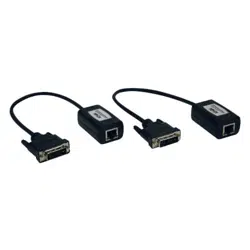
Using Cat5e/6 cable, connect one of the RJ45 output ports on the local
unit to the RJ45 input port on the B140-110 remote/repeater unit.
9
Connect a monitor to the DVI OUTPUT port on the remote/repeater unit
using a Tripp Lite P561-Series DVI-D Single Link Cable.
10
Connect the external power supply to the remote/repeater unit and plug
it into a Tripp Lite Surge Protector, PDU or UPS. The green Power LED
and the green RJ45 LEDs illuminate to indicate the unit is receiving
power.
17-08-508-933776.indb 24 11/27/2017 11:47:51 AM
Loading ...
Loading ...
Loading ...