Loading ...
Loading ...
Loading ...
EN-25
• a suitable isolating switch providing full disconnection from the mains power
supply is incorporated in the permanent wiring, mounted and positioned to
comply with the local wiring rules and regulations.
The isolating switch must be of an approved type and provide a 3 mm air gap
contact separation in all poles (or in all active [phase] conductors if the local
wiring rules allow for this variation of the requirements)
• the isolating switch will be easily accessible to the customer with the hob
installed
• you consult local building authorities and by-laws if in doubt regarding
installation
• you use heat-resistant and easy-to-clean finishes (such as ceramic tiles) for the
wall surfaces surrounding the hob.
When you have installed the hob, make sure that
• the power supply cable is not accessible through cupboard doors or drawers
• there is adequate flow of fresh air from outside the cabinetry to the base of the
hob
• if the hob is installed above a drawer or cupboard space, a thermal protection
barrier is installed below the base of the hob
• the isolating switch is easily accessible by the customer
Before locating the fixing brackets
The unit should be placed on a stable, smooth surface (use the packaging). Do not
apply force onto the controls protruding from the hob.
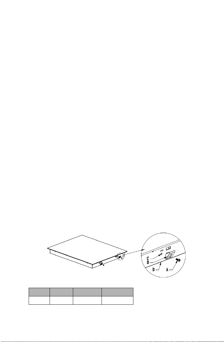
Adjusting the bracket position
Fix the hob on the work surface by screw 4 brackets on the bottom case of hob
(see picture) after installation.
A
B
C
D
Screw
Bracket
Screw hole
Bottom case
EN-26
Cautions
1. The induction hotplate must be installed by qualified personnel or technicians.
We have professionals at your service. Please never conduct the operation by
yourself.
2. The hob will not be installed directly above a dishwasher, fridge, freezer,
washing machine or clothes dryer, as the humidity may damage the hob
electronics
3.The induction hotplate shall be installed such that better heat radiation can be
ensured to enhance its reliability.
4. The wall and induced heating zone above the table surface shall withstand heat.
5. To avoid any damage, the sandwich layer and adhesive must be resistant to
heat.
Connecting the hob to the mains power supply
This hob must be connected to the mains power supply only by a suitably qualified person.
Before connecting the hob to the mains power supply, check that:
1.
the domestic wiring system is suitable for the power drawn by the hob.
2.
the voltage corresponds to the value given in the rating plate
3.
the power supply cable sections can withstand the load specified on the rating plate.
To connect the hob to the mains power supply, do not use adapters, reducers, or branching
devices, as they can cause overheating and fire.
The power supply cable must not touch any hot parts and must be positioned so that its
temperature will not exceed 75˚C at any point.
Check with an electrician whether the domestic wiring system is suitable without alterations.
Any alterations must only be made by a qualified electrician.
Loading ...
Loading ...
Loading ...