Loading ...
Loading ...
Loading ...

7
8.0 Electrical connections
All electrical connections must
be made by a qualified electrician. Failure to
comply may result in serious injury.
Disconnect machine from
power source before changing any voltage
components. Failure to comply may result in
serious injury.
The HBS-1321W band saw is rated at 230/460V,
3-phase and is prewired 230 volt from the factory.
Confirm power source available at the saw's
location is the same as the saw is wired. To switch
the HBS-1321W from 230V to 460V, the following
items will have to be changed. NOTE: Band saw
must always be properly grounded.
1. Main Motor: Follow diagram inside junction
box cover.
2. Coolant Pump: Follow diagram inside junction
box cover.
3. Control Transformer: Open electrical panel
on rear of base and switch only the one 230V
primary wire on transformer to the 460V
position.
4. Hydraulic Pump: Remove access panel and
follow diagram inside junction box cover.
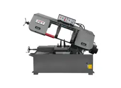
9.0 Controls
Refer to Figure 4.
Figure 4
A. Power Indicator Light: Lit whenever machine
has power.
B. Start Button: Depress to start band saw. Will
not work if emergency button is depressed.
C. Stop Button: Depress to stop band saw.
D. Emergency Stop Button: Depress to
immediately stop all machine functions.
E. Arm Up Button: Depress to raise arm.
F. Arm Down Button: Depress to lower arm.
G. Coolant Switch: Turn arrow to ON starting
flow of coolant. Turn arrow to OFF stopping
flow of coolant. Blade must be circulating for
coolant pump to work.
H. Downfeed Rate Knob: Turn clockwise to
increase down feed rate. Turn counter-
clockwise to decrease down feed rate. See
sect. 11.7, Adjusting feed rate.
10.0 Prior to operation
1. All JET band saws are designed and intended
for use by properly trained and experienced
personnel only. If you are not familiar with the
proper and safe operation of a band saw, do
not use until proper training and knowledge
have been obtained.
2. Check that blade tooth direction matches
diagram on blade guides.
3. Check to see that blade is properly seated on
wheels after applying correct tension
(approximately 25,000 lbs.).
4. Check blade guides for proper adjustments.
See sect. 11.9, Blade guide adjustment.
5. Position sliding blade guide arms as close to
workpiece as possible.
6. Select proper speed and feed rate for material
being cut. Refer to Machinery’s Handbook or
similar source for speed and feed charts.
7. Material to be cut must be securely held in the
vise. See sect. 11.1 through 11.3.
8. Check to see that coolant level is adequate
and turn on coolant pump if material to be cut
requires it. See sect. 12.3, Coolant pump.
9. Do not start cut on a sharp edge.
11.0 Adjustments
With the exception of blade
tracking, disconnect machine from the power
source before making adjustments or changing
vise position. Failure to comply may cause
serious injury.
11.1 Adjusting vise square to blade
(Position A, Figure 5)
1. Place a machinist's square on the bed against
the blade and the vise. The square should lie
along the entire length of the vise and blade
without a gap.
Loading ...
Loading ...
Loading ...
