Loading ...
Loading ...
Loading ...
2 RESET BUTTON ... See "Motor Specifications and
Electrical Requirements" section, "Motor Safety
Protection."
3
4
5
ELEVATION HANDWHEEL ... elevates or lowers the
blade. Turn clockwise to elevate ... counterclockwise
to lower.
NOTE: WHEN THE BLADE IS TILTED TO 45° , IT
CANNOT BE LOWERED ALL THE WAY BELOW
THE TABLE. IT WILL PROJECT APPROX. 1/2 IN.
TILT HANDWHEEL ... tilts the blade for bevel
cutting. Turn clockwise to tilt toward left ...
counterclockwise to tilt toward right.
When the blade istilted to the LEFT asfar asit will go,
it should be at 45 ° to the table and the bevel pointer
should point 45 ° .
NOTE: There are LIMIT STOPS inside the saw which
prevent the blade from tilting beyond 45° to the LEFT
and 90° to the RIGHT. (See "Adjustments" section
"Blade Tilt, or Squarenessof Blade to Table").
RIP FENCE ... is locked in place by tightening the
lock knob. To move the fence, loosen the lock knob
and graspthe fence with one hand at the front.
Holes are provided in the rid fence for attaching a wood
facing when using the dado head, or molding head.
Select a piece of smooth straight wood approx. 3/4 in.
thick and the same size as the rip fence.
Attach it to the fence with three Round Head # 10
Wood Screws 2 in. long. To remove the facing, loosen
the screws, slide the facing forward and pull the screws
through the round holes.
If you are making a rip type cut in material thinner
than 3/16 in. whi e the fence is positioned over the
depressedarea of table extension, the facing should be
attached to the fence so that the bottom edge touches
the top surface of the extension. In this case, the facing
must be shorter than the fence. This will prevent thin
material from sliding under the rip fence.
WOOD FACING
\
/ /
ROUND HEAD
# 10 WOOD SCREWS
6
MITER GAUGE . . . head is locked in position for
crosscutting or mitering by tightening the lock knob.
ALWAYS LOCK IT SECURELY WHEN IN USE.
Notches are provided in the miter gauge for attaching
an AUXILIARY FACING to make it easier to cut long
pieces. Be positive facing does not interfere with the
proper operation of the sawblade guard.
Select a suitable piece of smooth straight wood.., drill
two holes through it and attach it with screws.
NOTE: When bevel crosscutting, attach facing so that it
extends to the right of the miter gauge and use the miter
gauge in the groove to the right of the blade.
7
8
\
\
AUXILIARY FACING
BLADEGUARD must always be in place and working
properly for all thru-sawing cuts. That is, all cuts
whereby 1the blade cuts completely through the
workpiece.
To remove the guard for special operations, loosen the
wingscrews and move spreader away from saw and lift
upwards. DO NOT DISTURB THE SETTING OF THE
HEX NUTS,
When replacing the guard, make sure the spreader is
moved toward front of saw so that wingscrews are at
end of slots. TIGHTEN THE WlNGSCREWS
SECU RELY.
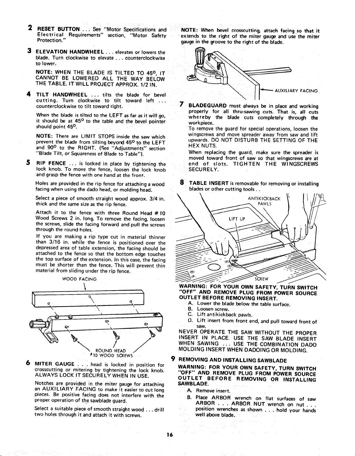
TABLE INSERT is removable for removing or installing
blades or other cutting tools..
ANTIKICKBACKpAwLS _/
\
\
9
SCREW
WARNING: FOR YOUR OWN SAFETY, TURN SWITCH
"OFF" AND REMOVE PLUG FROM POWER SOURCE
OUTLET BEFORE REMOVING INSERT.
A. Lower the blade below the table surface.
B. Loosen screw.
C. Lift antikickback pawls.
D. Lift insert from front end, and pull toward front of
saw,
NEVER OPERATE THE SAW WITHOUT THE PROPER
INSERT IN PLACE. USE THE SAW BLADE INSERT
WHEN SAWING ... USE THE COMBINATION DADO
MOLDING INSE-RT WHEN DADOING OR MOLDING.
REMOVING AND INSTALLING SAWBLADE
WARNING: FOR YOUR OWN SAFETY, TURN SWITCH
"OFF" AND REMOVE PLUG FROM POWER SOURCE
OUTLET BEFORE REMOVING OR INSTALLING
SAWBLADE.
A. Remove insert.
B. Place ARBOR wrench on flat surfaces of saw
ARBOR . . . ARBOR NUT wrench on nut . ..
position wrenches as shown . . . hold your hands
well above blade.
16
Loading ...
Loading ...
Loading ...