Loading ...
Loading ...
Loading ...
11
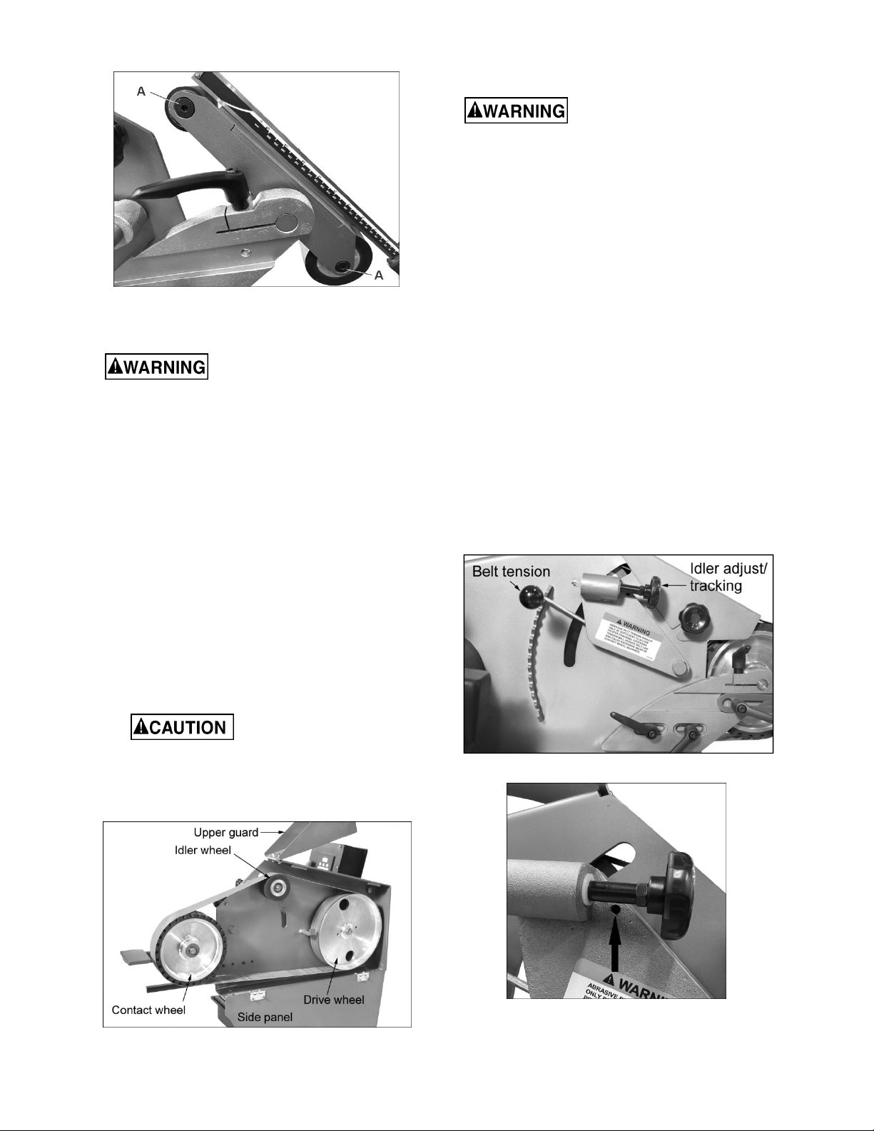
Figure 7-1a: wheel-to-platen adjustment
7.3 Installing/replacing grinding belt
Do not operate machine with
side panel open.
1. Lower belt tension lever (see Figure 7-3) to
release tension on belt.
2. Loosen knob and raise upper guard (see Figure
7-2). Open side panel by turning its knob and
lowering panel on its hinges.
3. If required, loosen work rest to provide
clearance for belt removal.
4. Remove belt from drive wheel, idler wheel, and
contact wheel. Install replacement belt centered
over drive wheel, idler wheel, and contact
wheel. Make sure direction arrows on belt
match machine operation.
5. Raise belt tension lever to tighten belt against
the wheels. Tighten belt until it is just taut. Do
not over-tension the abrasive belt. A moderate
tension will provide faster cutting, longer belt
life, and better tracking.
Excessive belt tension will
reduce belt life and cause excessive wear of
contact wheel bearings. Belt tension should
only be sufficient to allow proper tracking.
6. Check belt tracking; see sect. 7.4.
Figure 7-2: belt replacement
7.4 Belt tracking
Do not operate machine with
side panel open.
1. Loosen knob and raise upper guard. Open side
panel by turning its knob.
2. Spin drive wheel by hand and check tracking of
belt. If belt tracks to right or left, adjustment is
required.
3. Turn idler adjust screw (Figure 7-3) clockwise to
cause belt to track right. Turn idler screw
counterclockwise to cause belt to track left.
Perform this in small increments and allow belt
to respond to the changes.
4. Close side panel and secure by turning knob on
panel. Lower upper belt guard and secure with
knob.
5. Turn on grinder. Check belt tracking; belt should
remain centered on contact wheel. Make further
adjustments as needed according to step #3.
6. If belt still does not track properly, increase belt
tension and repeat steps 1 through 5.
7. The set screw in the idler casting (see Figure 7-
3a) can be turned to adjust the angle of the idler,
and make the belt completely parallel to the
three wheels (contact, drive and idler).
Figure 7-3: belt tracking
Figure 7-3a: set screw
Loading ...
Loading ...
Loading ...