Loading ...
Loading ...
Loading ...
10
6.2.2 Variable speed model (SWG-272VS)
1. Remove existing plug from power cable and
attach a UL/CSA listed plug designed for 230V
power; or “hardwire” the machine directly to a
panel. If hardwiring make sure a disconnect is
provided for the operator.
No internal rewiring is needed for the inverter to
accept the new input voltage.
6.3 Extension cords
The use of extension cords is discouraged; try to
position your machine within reach of the power
supply. If an extension cord becomes necessary,
make sure the cord rating is suitable for the
amperage listed on the machine’s motor plate. An
undersized cord will cause a drop in line voltage
resulting in loss of power and overheating.
Use the chart in Table 2 as a general guide in
choosing the correct size cord. If in doubt, use the
next heavier gauge. The smaller the gauge number,
the heavier the cord.
Recommended Gauges (AWG) of Extension Cords
Amp Rating Volts Total length of cord in feet
More
Than
Not
More
Than
120
240
25
50
50
100
100
200
150
300
AWG
0 6 18 16 16 14
6 10 18 16 14 12
10 12 16 16 14 12
12 16 14 12
Not
Recommended
Table 2
7.0 Adjustments
7.1 Platen or Wheel installation
Move switch to OFF to avoid
personal injury.
To install either the platen or the 8-inch serrated
wheel:
1. Pull out on tension lever (shown in Figure 7-3)
and lower it, to release tension on the belt.
2. Loosen knob and raise upper guard (see Figure
7-2). Open side panel by turning its knob and
lowering panel on its hinges.
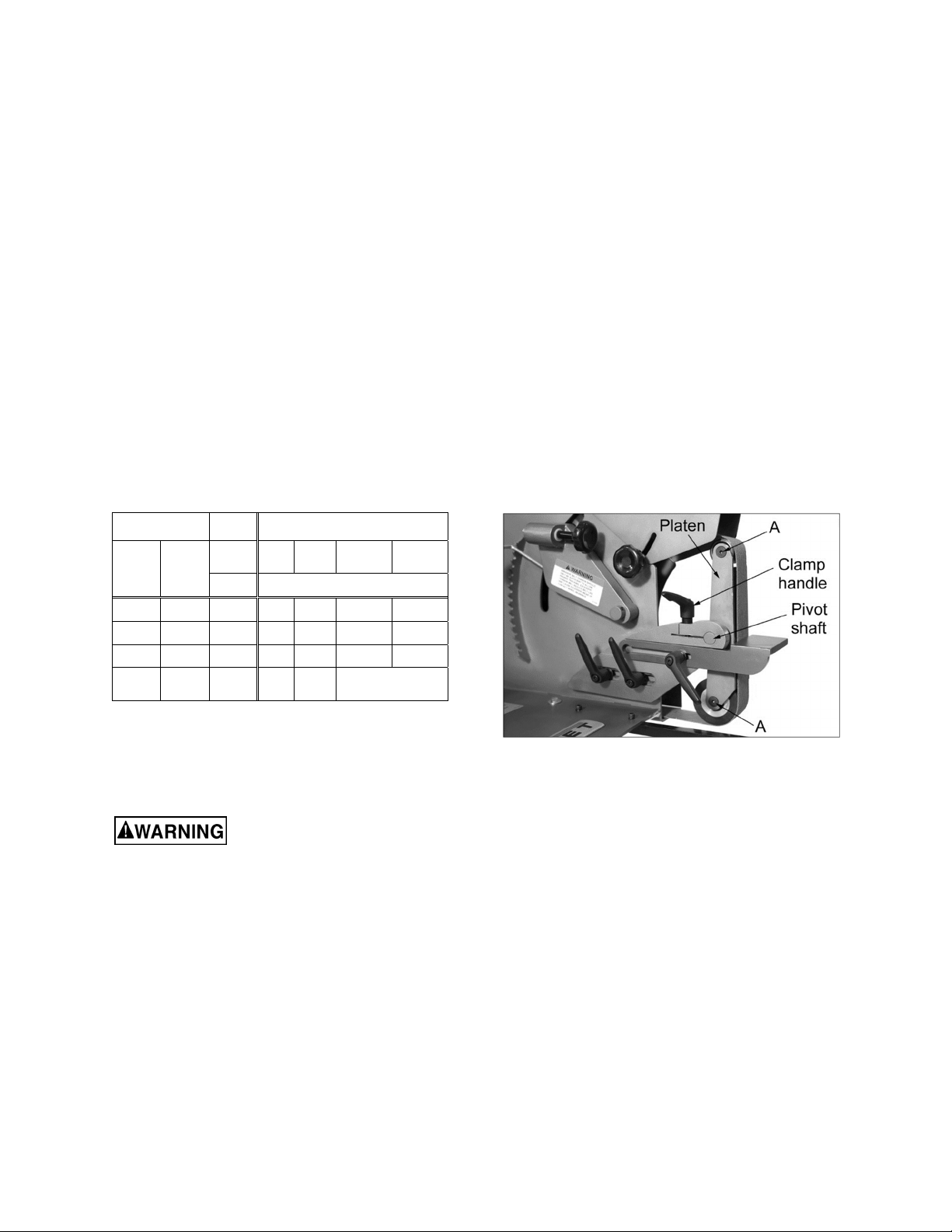
3. Loosen clamp handle on head casting. See
Figure 7-1.
4. Install pivot shaft of platen (or shaft of wheel) all
the way into head casting, as shown in Figure
7-1.
5. Position platen as desired:
For grinding flat or angular workpieces,
position platen with platen surface facing
outward.
For grinding of cylindrical workpieces,
position platen with “yoke” side facing
outward.
6. Set platen at desired angle and tighten clamp
handle.
[See sect. 7.2 before installing belt, then return
to step #7.]
7. Install and track the abrasive belt (see sect. 7.3
and 7.4).
8. Raise tension lever to set belt tension. Do not
overtighten.
9. Bring upper guard down into position and adjust
so that it will not contact abrasive belt. Tighten
upper guard knob.
10. Adjust work rest to 1/16 inch from belt.
Figure 7-1: installing platen assembly
7.2 Platen wheel adjustment
The platen wheels have eccentric shafts, which
allow adjustment of the wheels in relation to the
platen, either flush to platen or according to user
needs. See Figure 7-1a.
Remove the abrasive belt from the platen, and
remove the work rest. Place a straight edge on the
platen and across both wheels. Turn one or both
shaft screws (A) as needed.
Loading ...
Loading ...
Loading ...