Loading ...
Loading ...
Loading ...
4
36” GAS RANGETOP INSTALLATION INSTRUCTIONS
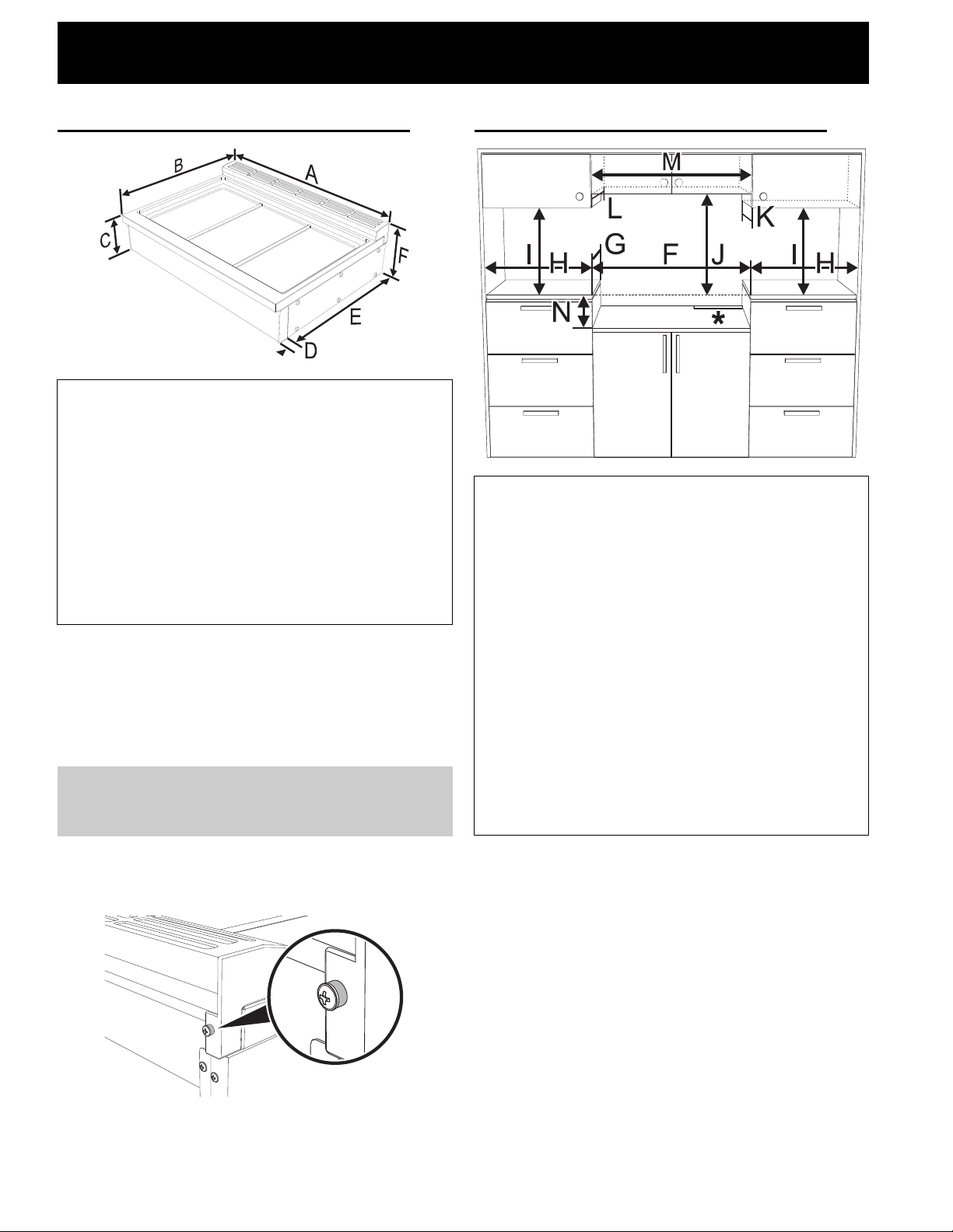
Product Dimensions
1. Dimension B and clearance G (next table) varies
according to the presence of the rear spacers
and its screws: the maximum is obtained with the
rear spacer and the minimum without it. The rear
spacer can be removed in case of island installa-
tion or if the back wall is non-combustible.
If removing the rear spacers remove its screws as
well. The total thickness of the spacers and the
screw heads is 0.256” (6.5 mm).
Cabinet clearances
Clearance J can have the following values:
• J = 36” / 914 mm minimum clearance between
the top of the cooking surface and the bottom of
an unprotected wood or metal cabinet.
• J = 30” / 762 mm minimum when the bottom of
wood or metal cabinet is protected by not less
than 1/4-inch-thick flame-retardant millboard cov-
ered with not less than No. 28 MSG sheet steel,
0.015-inch-thick stainless steel, 0.024-inch-thick
aluminum, or 0.020-inch-thick copper. Clearances
from non-combustible materials are not part of the
ANSI Z21.1 scope and are not certified by CSA.
Clearances of less than 30'' should be approved
by the local codes and/or by the local authority
having jurisdiction.
A
912.4 mm 35 15/16"
B
1
max: 688 mm
min: 681.5 mm
max: 27 1/8"
min: 26 13/16”
C
190.5 mm 7 1/2"
D
46.5 mm 1 13/16"
E
604 mm 23 12/16”
F
241 mm 9 1/2"
NOTE: Clearances from non-combustible materi-
als are not part of the ANSI Z21.1 scope and are
not certified by CSA.
F
914 mm 36”
G
1
max: 619 mm
min: 612.5 mm
max: 24 3/8”
min: 24 1/8”
H
min. 508 mm min. 20”
I
min. 457 mm min. 18”
J
see notes below
K
max. 330 mm max. 13”
L
max. 330 mm max. 13”
M
min. 914 mm min. 36”
N
190.5 mm 7 1/2”
Loading ...
Loading ...
Loading ...